
16A: Newton’s Laws #3: Components, Friction, Ramps, Pulleys, and Strings


( \newcommand{\kernel}{\mathrm{null}\,}\)
Having learned how to use free body diagrams, and then having learned how to create them, you are in a pretty good position to solve a huge number of Newton’s 2nd Law problems. An understanding of the considerations in this chapter will enable to you to solve an even larger class of problems. Again, we use examples to convey the desired information.
A professor is pushing on a desk with a force of magnitude F at an acute angle θ below the horizontal. The desk is on a flat, horizontal tile floor and it is not moving. For the desk, draw the free body diagram that facilitates the direct and straightforward application of Newton’s 2nd Law of motion. Give the table of forces.
Solution
While not a required part of the solution, a sketch often makes it easier to come up with the correct free body diagram. Just make sure you don’t combine the sketch and the free body diagram. In this problem, a sketch helps clarify what is meant by “at an acute angle θ below the horizontal.”
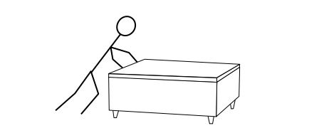
Pushing with a force that is directed at some acute angle below the horizontal is pushing horizontally and downward at the same time.
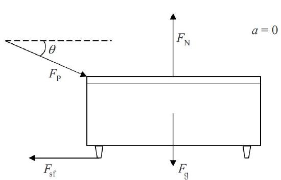
Here is the initial free body diagram and the corresponding table of forces
| Symbol=? | Name | Agent | Victim |
|---|---|---|---|
| FN |
Normal Force | The Floor | Desk |
| Fsf |
Static Friction Force | The Floor | Desk |
| Fg=mg |
Gravitational Force | The Earth's Gravitational Field | Desk |
| Fp |
Force of Professor | Hands of Professor | Desk |
Note that there are no two mutually perpendicular lines to which all of the forces are parallel. The best choice of mutually perpendicular lines would be a vertical and a horizontal line. Three of the four forces lie along one or the other of such lines. But the force of the professor does not. We cannot use this free body diagram directly. We are dealing with a case which requires a second free body diagram.
Cases Requiring a Second Free Body Diagram in Which One of More of the Forces that was in the First Free Body Diagram is Replaced With its Components
Establish a pair of mutually perpendicular lines such that most of the vectors lie along one or the other of the two lines. After having done so, break up each of the other vectors, the ones that lie along neither of the lines, (let’s call these the rogue vectors) into components along the two lines. (Breaking up vectors into their components involves drawing a vector component diagram.) Draw a second free body diagram, identical to the first, except with rogue vectors replaced by their component vectors. In the new free body diagram, draw the component vectors in the direction in which they actually point and label them with their magnitudes (no minus signs).
For the case at hand, our rogue force is the force of the professor. We break it up into components as follows:
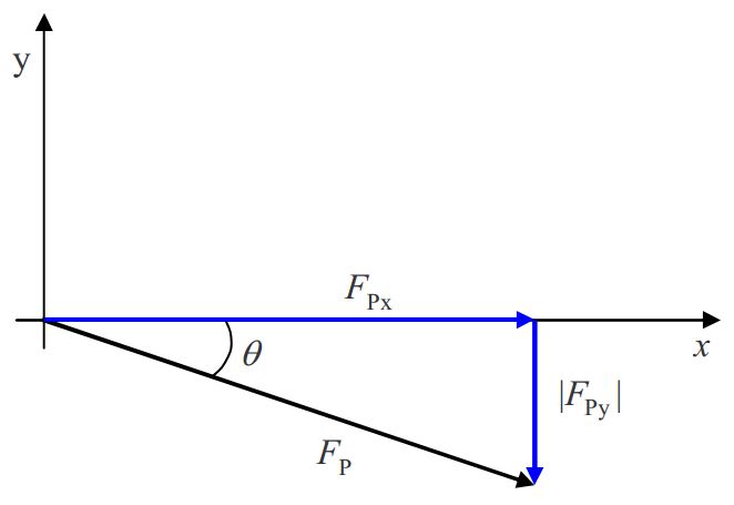
FPxFP=cosθ|FPy|FP=sinθ
FPx=FPcosθ|FPy|=FPsinθ
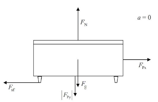
Then we draw a second free body diagram, the same as the first, except with FP replaced by its component vectors:
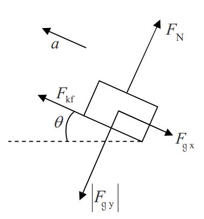
A wooden block of mass m is sliding down a flat metal incline (a flat metal ramp) that makes an acute angle θ with the horizontal. The block is slowing down. Draw the directly-usable free body diagram of the block. Provide a table of forces.
Solution
We choose to start the solution to this problem with a sketch. The sketch facilitates the creation of the free body diagram but in no way replaces it.
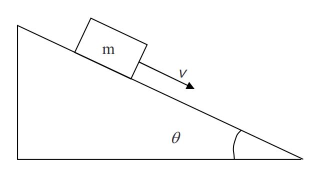
Since the block is sliding in the down-the-incline direction, the frictional force must be in the up-the-incline direction. Since the block’s velocity is in the down-the-incline direction and decreasing, the acceleration must be in the up-the-incline direction.
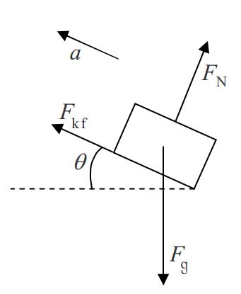
| Symbol=? | Name | Agent | Victim |
|---|---|---|---|
| FN |
Normal Force | The Ramp | The Block |
| Fkf=μKFN |
Kinetic Friction Force | The Ramp | The Block |
| Fg=mg |
Gravitation Force | The Earth's Gravitational Field | The Block |
No matter what we choose for a pair of coordinate axes, we cannot make it so that all the vectors in the free body diagram are parallel to one or the other of the two coordinate axes lines. At best, the pair of lines, one line parallel to the frictional force and the other perpendicular to the ramp, leaves one rogue vector, namely the gravitational force vector. Such a coordinate system is tilted on the page.
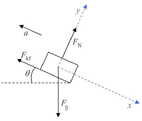
Cases Involving Tilted Coordinate Systems
For effective communication purposes, students drawing diagrams depicting phenomena occurring near the surface of the earth are required to use either the convention that downward is toward the bottom of the page (corresponding to a side view) or the convention that downward is into the page (corresponding to a top view). If one wants to depict a coordinate system for a case in which the direction “downward” is parallel to neither coordinate axis line, the coordinate system must be drawn so that it appears tilted on the page.
In the case of a tilted-coordinate system problem requiring a second free body diagram of the same object, it is a good idea to define the coordinate system on the first free body diagram. Use dashed lines so that the coordinate axes do not look like force vectors. Here we redraw the first free body diagram. (When you get to this stage in a problem, just add the coordinate axes to your existing diagram.)
Now we break up Fg into its x, y component vectors. This calls for a vector component diagram.
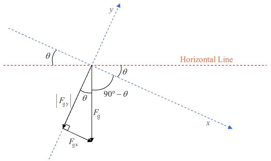
FgxFg=sinθ|Fgy|Fg=cosθ
Fgx=Fgsinθ|Fgy|=Fgcosθ
Next, we redraw the free body diagram with the gravitational force vector replaced by its component vectors.
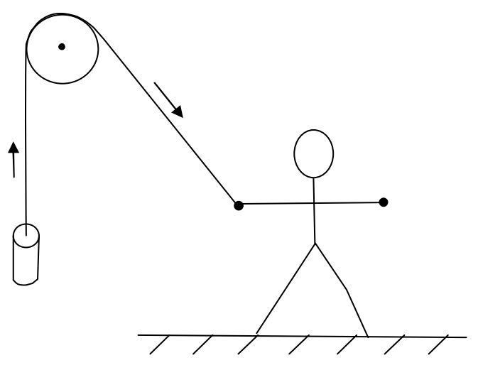
A solid brass cylinder of mass m is suspended by a massless string which is attached to the top end of the cylinder. From there, the string extends straight upward to a massless ideal pulley. The string passes over the pulley and extends downward, at an acute angle theta to the vertical, to the hand of a person who is pulling on the string with force FT. The pulley and the entire string segment, from the cylinder to hand, lie in one and the same plane. The cylinder is accelerating upward. Provide both a free body diagram and a table of forces for the cylinder.
Solution
A sketch comes in handy for this one:
To proceed with this one, we need some information on the effect of an ideal massless pulley on a string that passes over the pulley.
Effect of an Ideal Massless Pulley
The effect of an ideal massless pulley on a string that passes over the pulley is to change the direction in which the string extends, without changing the tension in the string.
By pulling on the end of the string with a force of magnitude FT, the person causes there to be a tension FT in the string. (The force applied to the string by the hand of the person, and the tension force of the string pulling on the hand of the person, are a Newton’s-3rd-law interaction pair of forces. They are equal in magnitude and opposite in direction. We choose to use one and the same symbol FT for the magnitude of both of these forces. The directions are opposite each other.) The tension is the same throughout the string, so, where the string is attached to the brass cylinder, the string exerts a force of magnitude FT directed away from the cylinder along the length of the string. Here is the free body diagram and the table of forces for the cylinder:
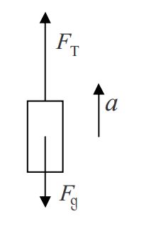
| Symbol=? | Name | Agent | Victim |
|---|---|---|---|
| FT |
Tension Force | The String | The Cylinder |
| Fg=mg |
Gravitational Force | The Earth's Gravitational Field | The Cylinder |
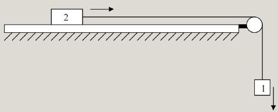
A cart of mass mc is on a horizontal frictionless track. One end of an ideal massless string segment is attached to the middle of the front end of the cart. From there the string extends horizontally, forward and away from the cart, parallel to the centerline of the track, to a vertical pulley. The string passes over the pulley and extends downward to a solid metal block of mass mB. The string is attached to the block. A person was holding the cart in place. The block was suspended at rest, well above the floor, by the string. The person has released the cart. The cart is now accelerating forward and the block is accelerating downward. Draw a free body diagram for each object.
Solution
A sketch will help us to arrive at the correct answer to this problem.
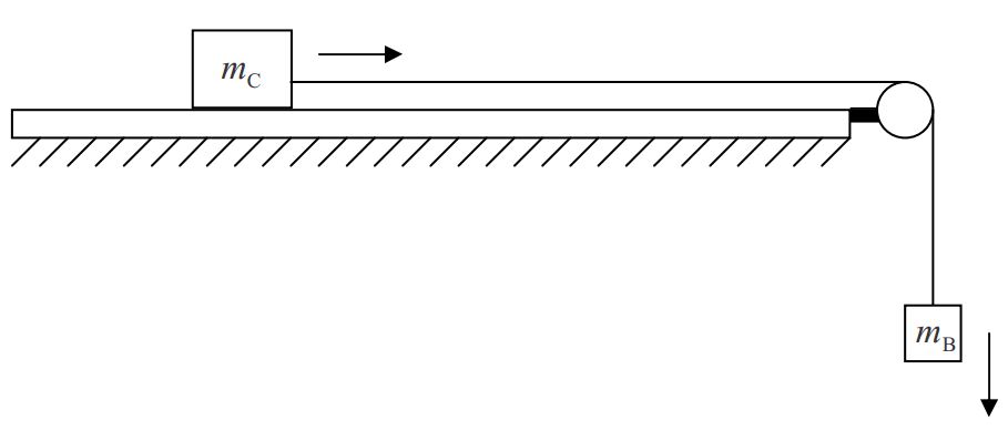
Recall from the last example that there is only one tension in the string. Call it FT. Based on our knowledge of the force exerted on an object by a string, viewed so that the apparatus appears as it does in the sketch, the string exerts a rightward force FT on the cart, and an upward force of magnitude FT on the block.
There is a relationship between each of several variables of motion of one object attached by a taut string, which remains taut throughout the motion of the object, and the corresponding variables of motion of the second object. The relationships are so simple that you might consider them to be trivial, but they are critical to the solution of problems involving objects connected by a taut spring.
The Relationships Among the Variables of Motion For Two Objects, One at One End and the Other at the Other
End, of an always-taut, Unstretchable String
Consider the following diagram.
Because they are connected together by a string of fixed length, if object 1 goes downward 5cm, then object 2 must go rightward 5cm. So if object 1 goes downward at 5cm/s then object 2 must go rightward at 5cm/s. In fact, no matter how fast object 1 goes downward, object 2 must go rightward at the exact same speed (as long as the string does not break, stretch, or go slack). In order for the speeds to always be the same, the accelerations have to be the same as each other. So if object 1 is picking up speed in the downward direction at, for instance, 5cm/s2, then object 2 must be picking up speed in the rightward direction at 5cm/s2. The magnitudes of the accelerations are identical. The way to deal with this is to use one and the same symbol for the magnitude of the acceleration of each of the objects. The ideas relevant to this simple example apply to any case involving two objects, one on each end of an inextensible string, as long as each object moves only along a line collinear with the string segment to which the object is attached.
Let’s return to the example problem involving the cart and the block. The two free body diagrams follow:
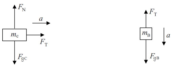
Note that the use of the same symbol FT in both diagrams is important, as is the use of the same symbol a in both diagrams.