
9B: Electric Current, EMF, and Ohm's Law
- Page ID
- 5936

\( \newcommand{\vecs}[1]{\overset { \scriptstyle \rightharpoonup} {\mathbf{#1}} } \)
\( \newcommand{\vecd}[1]{\overset{-\!-\!\rightharpoonup}{\vphantom{a}\smash {#1}}} \)
\( \newcommand{\dsum}{\displaystyle\sum\limits} \)
\( \newcommand{\dint}{\displaystyle\int\limits} \)
\( \newcommand{\dlim}{\displaystyle\lim\limits} \)
\( \newcommand{\id}{\mathrm{id}}\) \( \newcommand{\Span}{\mathrm{span}}\)
( \newcommand{\kernel}{\mathrm{null}\,}\) \( \newcommand{\range}{\mathrm{range}\,}\)
\( \newcommand{\RealPart}{\mathrm{Re}}\) \( \newcommand{\ImaginaryPart}{\mathrm{Im}}\)
\( \newcommand{\Argument}{\mathrm{Arg}}\) \( \newcommand{\norm}[1]{\| #1 \|}\)
\( \newcommand{\inner}[2]{\langle #1, #2 \rangle}\)
\( \newcommand{\Span}{\mathrm{span}}\)
\( \newcommand{\id}{\mathrm{id}}\)
\( \newcommand{\Span}{\mathrm{span}}\)
\( \newcommand{\kernel}{\mathrm{null}\,}\)
\( \newcommand{\range}{\mathrm{range}\,}\)
\( \newcommand{\RealPart}{\mathrm{Re}}\)
\( \newcommand{\ImaginaryPart}{\mathrm{Im}}\)
\( \newcommand{\Argument}{\mathrm{Arg}}\)
\( \newcommand{\norm}[1]{\| #1 \|}\)
\( \newcommand{\inner}[2]{\langle #1, #2 \rangle}\)
\( \newcommand{\Span}{\mathrm{span}}\) \( \newcommand{\AA}{\unicode[.8,0]{x212B}}\)
\( \newcommand{\vectorA}[1]{\vec{#1}} % arrow\)
\( \newcommand{\vectorAt}[1]{\vec{\text{#1}}} % arrow\)
\( \newcommand{\vectorB}[1]{\overset { \scriptstyle \rightharpoonup} {\mathbf{#1}} } \)
\( \newcommand{\vectorC}[1]{\textbf{#1}} \)
\( \newcommand{\vectorD}[1]{\overrightarrow{#1}} \)
\( \newcommand{\vectorDt}[1]{\overrightarrow{\text{#1}}} \)
\( \newcommand{\vectE}[1]{\overset{-\!-\!\rightharpoonup}{\vphantom{a}\smash{\mathbf {#1}}}} \)
\( \newcommand{\vecs}[1]{\overset { \scriptstyle \rightharpoonup} {\mathbf{#1}} } \)
\(\newcommand{\longvect}{\overrightarrow}\)
\( \newcommand{\vecd}[1]{\overset{-\!-\!\rightharpoonup}{\vphantom{a}\smash {#1}}} \)
\(\newcommand{\avec}{\mathbf a}\) \(\newcommand{\bvec}{\mathbf b}\) \(\newcommand{\cvec}{\mathbf c}\) \(\newcommand{\dvec}{\mathbf d}\) \(\newcommand{\dtil}{\widetilde{\mathbf d}}\) \(\newcommand{\evec}{\mathbf e}\) \(\newcommand{\fvec}{\mathbf f}\) \(\newcommand{\nvec}{\mathbf n}\) \(\newcommand{\pvec}{\mathbf p}\) \(\newcommand{\qvec}{\mathbf q}\) \(\newcommand{\svec}{\mathbf s}\) \(\newcommand{\tvec}{\mathbf t}\) \(\newcommand{\uvec}{\mathbf u}\) \(\newcommand{\vvec}{\mathbf v}\) \(\newcommand{\wvec}{\mathbf w}\) \(\newcommand{\xvec}{\mathbf x}\) \(\newcommand{\yvec}{\mathbf y}\) \(\newcommand{\zvec}{\mathbf z}\) \(\newcommand{\rvec}{\mathbf r}\) \(\newcommand{\mvec}{\mathbf m}\) \(\newcommand{\zerovec}{\mathbf 0}\) \(\newcommand{\onevec}{\mathbf 1}\) \(\newcommand{\real}{\mathbb R}\) \(\newcommand{\twovec}[2]{\left[\begin{array}{r}#1 \\ #2 \end{array}\right]}\) \(\newcommand{\ctwovec}[2]{\left[\begin{array}{c}#1 \\ #2 \end{array}\right]}\) \(\newcommand{\threevec}[3]{\left[\begin{array}{r}#1 \\ #2 \\ #3 \end{array}\right]}\) \(\newcommand{\cthreevec}[3]{\left[\begin{array}{c}#1 \\ #2 \\ #3 \end{array}\right]}\) \(\newcommand{\fourvec}[4]{\left[\begin{array}{r}#1 \\ #2 \\ #3 \\ #4 \end{array}\right]}\) \(\newcommand{\cfourvec}[4]{\left[\begin{array}{c}#1 \\ #2 \\ #3 \\ #4 \end{array}\right]}\) \(\newcommand{\fivevec}[5]{\left[\begin{array}{r}#1 \\ #2 \\ #3 \\ #4 \\ #5 \\ \end{array}\right]}\) \(\newcommand{\cfivevec}[5]{\left[\begin{array}{c}#1 \\ #2 \\ #3 \\ #4 \\ #5 \\ \end{array}\right]}\) \(\newcommand{\mattwo}[4]{\left[\begin{array}{rr}#1 \amp #2 \\ #3 \amp #4 \\ \end{array}\right]}\) \(\newcommand{\laspan}[1]{\text{Span}\{#1\}}\) \(\newcommand{\bcal}{\cal B}\) \(\newcommand{\ccal}{\cal C}\) \(\newcommand{\scal}{\cal S}\) \(\newcommand{\wcal}{\cal W}\) \(\newcommand{\ecal}{\cal E}\) \(\newcommand{\coords}[2]{\left\{#1\right\}_{#2}}\) \(\newcommand{\gray}[1]{\color{gray}{#1}}\) \(\newcommand{\lgray}[1]{\color{lightgray}{#1}}\) \(\newcommand{\rank}{\operatorname{rank}}\) \(\newcommand{\row}{\text{Row}}\) \(\newcommand{\col}{\text{Col}}\) \(\renewcommand{\row}{\text{Row}}\) \(\newcommand{\nul}{\text{Nul}}\) \(\newcommand{\var}{\text{Var}}\) \(\newcommand{\corr}{\text{corr}}\) \(\newcommand{\len}[1]{\left|#1\right|}\) \(\newcommand{\bbar}{\overline{\bvec}}\) \(\newcommand{\bhat}{\widehat{\bvec}}\) \(\newcommand{\bperp}{\bvec^\perp}\) \(\newcommand{\xhat}{\widehat{\xvec}}\) \(\newcommand{\vhat}{\widehat{\vvec}}\) \(\newcommand{\uhat}{\widehat{\uvec}}\) \(\newcommand{\what}{\widehat{\wvec}}\) \(\newcommand{\Sighat}{\widehat{\Sigma}}\) \(\newcommand{\lt}{<}\) \(\newcommand{\gt}{>}\) \(\newcommand{\amp}{&}\) \(\definecolor{fillinmathshade}{gray}{0.9}\)We now begin our study of electric circuits. A circuit is a closed conducting path through which charge flows. In circuits, charge goes around in loops. The charge flow rate is called electric current. A circuit consists of circuit elements connected together by wires. A capacitor is an example of a circuit element with which you are already familiar. We introduce some more circuit elements in this chapter. In analyzing circuits, we treat the wires as perfect conductors and the circuit elements as ideal circuit elements. There is a great deal of variety in the complexity of circuits. A computer is a complicated circuit. A flashlight is a simple circuit.
The kind of circuit elements that you will be dealing with in this course are two-terminal circuit elements. There are several different kinds of two-terminal circuit elements but they all have some things in common. A two-terminal circuit element is a device with two ends, each of which is a conductor. The two conductors are called terminals. The terminals can have many different forms. Some are wires, some are metal plates, some are metal buttons, and some are metal posts. One connects wires to the terminals to make a circuit element part of a circuit.
An important two-terminal circuit element is a seat of EMF. You can think of a seat of EMF as an ideal battery or as an ideal power supply. What it does is to maintain a constant potential difference (a.k.a. a constant voltage) between its terminals. One uses either the constant name \(\varepsilon\) (script \(E\)) or the constant name \(V\) to represent that potential difference.
To achieve a potential difference \(E\) between its terminals, a seat of EMF, when it first comes into existence, has to move some charge (we treat the movement of charge as the movement of positive charge) from one terminal to the other. The “one terminal” is left with a net negative charge and “the other” acquires a net positive charge. The seat of EMF moves charge until the positive terminal is at a potential \(E\) higher than the negative terminal. Note that the seat of EMF does not produce charge; it just pushes existing charge around. If you connect an isolated wire to the positive terminal, then it is going to be at the same potential as the positive terminal, and, because the charge on the positive terminal will spread out over the wire, the seat of EMF is going to have to move some more charge from the lower-potential terminal to maintain the potential difference. One rarely talks about the charge on either terminal of a seat of EMF or on a wire connected to either terminal. A typical seat of EMF maintains a potential difference between its terminals on the order of 10 volts and the amount of charge that has to be moved, from one wire whose dimensions are similar to that of a paper clip, to another of the same sort, is on the order of a pC (\(1\times 10^{-12}C\) ). Also, the charge pileup is almost instantaneous, so, by the time you finish connecting a wire to a terminal, that wire already has the charge we are talking about. In general, we don’t know how much charge is on the positive terminal and whatever wire might be connected to it, and we don’t care. It is minuscule. But, it is enough for the potential difference between the terminals to be the rated voltage of the seat of EMF.
You’ll recall that electric potential is something that is used to characterize an electric field. In causing there to be a potential difference between its terminals and between any pair of wires that might be connected to its terminals, the seat of EMF creates an electric field. The electric field depends on the arrangement of the wires that are connected to the terminals of the seat of EMF. The electric field is another quantity that we rarely discuss in analyzing circuits. We can typically find out what we need to find out from the value of the potential differenceE that the seat of EMF maintains between its terminals. But, the electric field does exist, and, in circuits, the electric field of the charge on the wires connected to the seat of EMF is what causes charge to flow in a circuit, and charge flow in a circuit is a huge part of what a circuit is all about.
We use the symbol
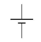
to represent a seat of EMF in a circuit diagram (a.k.a. a schematic diagram of a circuit) where the two collinear line segments represent the terminals of the seat of EMF, the one connected to the shorter of the parallel line segments being the negative, lower-potential, terminal; and; the one connected to the longer of the parallel line segments being the positive, higher-potential, terminal.
The other circuit element that I want to introduce in this chapter is the resistor. A resistor is a poor conductor. The resistance of a resistor is a measure of how poor a conductor the resistor is. The bigger the value of resistance, the more poorly the circuit element allows charge to flow through itself. Resistors come in many forms. The filament of a light bulb is a resistor. A toaster element (the part that glows red when the toaster is on) is a resistor. Humans manufacture small ceramic cylinders (with a coating of carbon and a wire sticking out each end) to have certain values of resistance. Each one has its value of resistance indicated on the resistor itself. The symbol
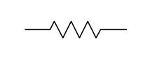
is used to represent a resistor in a circuit diagram. The symbol R is typically used to represent the value of the resistance of a resistor.
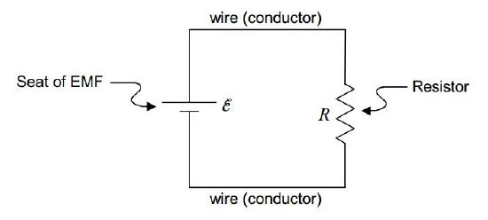
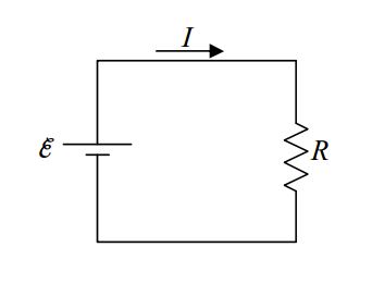
We are now ready to consider the following simple circuit:
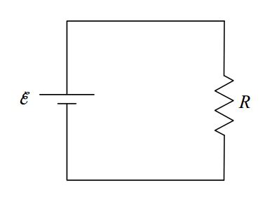
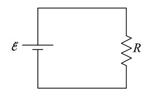
Here it is again without so many labels:
The upper wire (conductor) has one value of electric potential (call it \(\varphi_{HI}\)) and the lower wire has another value of electric potential (call it \(\varphi_{LOW}\)) such that the difference \(\space \varphi_{HI}-\varphi_{LOW}\space\) is \(\space\varepsilon\).
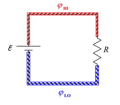
\[\varphi_{HI}-\varphi_{LOW}=\varepsilon \nonumber \]
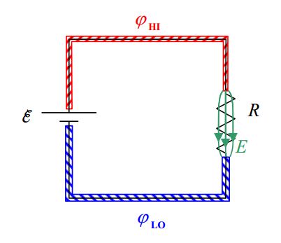
In order to maintain the potential difference \(\varepsilon\) between the two conductors, the seat of EMF causes there to be a minuscule amount of positive charge on the upper wire and the same amount of negative charge on the lower wire. This charge separation causes an electric field in the resistor.
(We carry out this argument in the positive charge carrier model. While it makes no difference for the circuit, as a point of fact, it is actually negatively charged particles moving in the opposite direction. The effect is the same.)
It is important to realize that every part of the circuit is chock full of both kinds of charge. The wire, the resistor, everything is incredibly crowded with both positive and negative charge. One kind of charge can move against the background of the other. Now the electric field in the resistor pushes the positive charge in the resistor in the direction from the higher-potential terminal toward the lower-potential terminal.
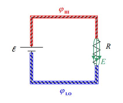
Pushing positive charge onto the lower-potential wire would tend to raise the potential of the lower-potential wire and leave the upper end of the resistor with a negative charge. I say “would” because any tendency for a change in the relative potential of the two wires is immediately compensated for by the seat of EMF. Remember, that’s what the seat of EMF does, it maintains a constant potential difference between the wires. To do so in the case at hand, the seat of EMF must pull some positive charges from the lower-potential wire and push them onto the higher-potential wire. Also, any tendency of the upper end of the resistor to become negative immediately results in an attractive force on the positive charge in the higher-potential wire. This causes that positive charge to move down into the resistor in the place of the charge that just moved along the resistor toward the lower-potential wire. The net effect is a continual movement of charge, clockwise around the loop, as we view it in the diagram, with the net amount of charge in any short section of the circuit never changing. Pick a spot anywhere in the circuit. Just as fast as positive charge moves out of that spot, more positive charge from a neighboring spot moves in. What we have is this whole crowded mass of positive charge carriers moving clockwise around the loop, all because of the electric field in the resistor, and the EMF’s “insistence” on maintaining a constant potential difference between the wires.
Now draw a dotted line across the path of the circuit, at any point in the circuit, as indicated below.
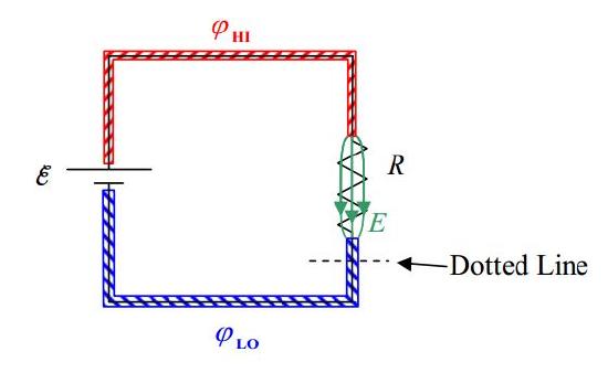
The rate at which charge crosses that line is the charge flow rate at that point (the point at which you drew the dotted line) in the circuit. The charge flow rate, how many coulombs-of charge per-second are crossing that line is called the electric current at that point. In the case at hand, because the whole circuit consists of a single loop, the current is the same at every point in the circuit—it doesn’t matter where you “draw the line.” The symbol that one typically uses to represent the value of the current is \(I\).
In analyzing a circuit, if the current variable is not already defined for you, you should define it
by drawing an arrow on the circuit and labeling it \(I\) or \(I\) with a subscript.
The units for current are coulombs per second (\(C/s\)). That combination of units is given a name: the ampere, abbreviated \(A\).
\[1A=1\frac{C}{s} \nonumber \]
Now about that resistor: In our positive charge carrier model, the charged particles that are free to move in the resistor experience a force exerted on them by the electric field, in the direction of the electric field. As a result, they experience acceleration. But, the background material making up the substance of which the charge carriers are a part, exerts a velocity dependent retarding force on the charge carriers. The faster they go, the bigger the retarding force. Upon completion of the circuit (making that final wire-to-terminal connection), the charge carriers in the resistor, almost instantaneously, reach a terminal velocity at which the retarding force on a given charge carrier is just as great as the force exerted by the electric field on that charge carrier. The value of the terminal velocity, along with the number-of-charge-carriers-per-volume in the resistor, and the cross-sectional area of the poorly-conducting material making up the resistor, determine the charge flow rate, the current, in the resistor. In the simple circuit under consideration, the charge flow rate in the resistor is the charge flow rate everywhere in the circuit.
The value of the terminal velocity itself depends on how strong the electric field is, and, on the nature of the retarding force. The nature of the retarding force depends on what kind of material the resistor is made of. One kind of material will result in a bigger terminal velocity for the same electric field as another kind of material. Even with one kind of material, there’s the question of how the retarding force depends on the velocity. Is it proportional to the square of the velocity, the log of the velocity, or what? Experiment shows that in an important subset of materials, over certain ranges of the terminal velocity, the retarding force is proportional to the velocity itself. Such materials are said to obey Ohm’s law and are referred to as ohmic materials.
Consider the resistor in the simple circuit we have been dealing with.
If you double the voltage across the resistor (by using a seat of EMF that maintains twice the potential difference between its terminals as the original seat of EMF) then you double the electric field in the resistor. This doubles the force exerted on each charge carrier. This means that, at the terminal velocity of any charge carrier, the retarding force has to be twice as great. (Since, upon making that final circuit connection, the velocity of the charge carriers increases until the retarding force on each charge carrier is equal in magnitude to the applied force.) In an ohmic material, if the retarding force is twice as great, then the velocity is twice as great. If the velocity is twice as great, then the charge flow rate, the electric current, is twice as great. So, doubling the voltage across the resistor doubles the current. Indeed, for a resistor that obeys Ohm’s Law, the current in a resistor is directly proportional to the voltage across the resistor.
Summarizing: When you put a voltage across a resistor, there is a current in that resistor. The ratio of the voltage to the current is called the resistance of the resistor.
\[R=\frac{V}{I} \nonumber \]
This definition of resistance is consistent with our understanding that the resistance of a resistor is a measure of how lousy a conductor it is. Check it out. If, for a given voltage across the resistor, you get a tiny little current (meaning the resistor is a very poor conductor), the value of resistance \(R=\frac{V}{I}\) with that small value of current in the denominator, is very big. If, on the other hand, for the same voltage, you get a big current (meaning the resistor is a good conductor), then the value of resistance \(R=\frac{V}{I}\) is small.
If the material of which the resistor is made obeys Ohm’s Law, then the resistance \(R\) is a constant, meaning that its value is the same for different voltages. The relation \(R=\frac{V}{I}\) is typically written in the form \(V=IR\).
The resistance \(R\), in the expression \(V = IR\), is a constant.
Ohm’s Law is good for resistors made of certain materials (called ohmic materials) over a limited range of voltages.
Units of Resistance
Given that the resistance of a resistor is defined as the ratio of the voltage across that resistor to the resulting current in that resistor,
\[R=\frac{V}{I} \nonumber \]
it is evident that the unit of resistance is the volt per ampere, \(\frac{V}{A}\). This combination unit is given a name. We call it the ohm, abbreviated \(\Omega\), the Greek letter upper-case omega.
\[1\Omega=1 \frac{\mbox{volt}}{\mbox{ampere}} \nonumber \]