
B10: Resistors in Series and Parallel; Measuring I & V
- Page ID
- 5939

\( \newcommand{\vecs}[1]{\overset { \scriptstyle \rightharpoonup} {\mathbf{#1}} } \)
\( \newcommand{\vecd}[1]{\overset{-\!-\!\rightharpoonup}{\vphantom{a}\smash {#1}}} \)
\( \newcommand{\dsum}{\displaystyle\sum\limits} \)
\( \newcommand{\dint}{\displaystyle\int\limits} \)
\( \newcommand{\dlim}{\displaystyle\lim\limits} \)
\( \newcommand{\id}{\mathrm{id}}\) \( \newcommand{\Span}{\mathrm{span}}\)
( \newcommand{\kernel}{\mathrm{null}\,}\) \( \newcommand{\range}{\mathrm{range}\,}\)
\( \newcommand{\RealPart}{\mathrm{Re}}\) \( \newcommand{\ImaginaryPart}{\mathrm{Im}}\)
\( \newcommand{\Argument}{\mathrm{Arg}}\) \( \newcommand{\norm}[1]{\| #1 \|}\)
\( \newcommand{\inner}[2]{\langle #1, #2 \rangle}\)
\( \newcommand{\Span}{\mathrm{span}}\)
\( \newcommand{\id}{\mathrm{id}}\)
\( \newcommand{\Span}{\mathrm{span}}\)
\( \newcommand{\kernel}{\mathrm{null}\,}\)
\( \newcommand{\range}{\mathrm{range}\,}\)
\( \newcommand{\RealPart}{\mathrm{Re}}\)
\( \newcommand{\ImaginaryPart}{\mathrm{Im}}\)
\( \newcommand{\Argument}{\mathrm{Arg}}\)
\( \newcommand{\norm}[1]{\| #1 \|}\)
\( \newcommand{\inner}[2]{\langle #1, #2 \rangle}\)
\( \newcommand{\Span}{\mathrm{span}}\) \( \newcommand{\AA}{\unicode[.8,0]{x212B}}\)
\( \newcommand{\vectorA}[1]{\vec{#1}} % arrow\)
\( \newcommand{\vectorAt}[1]{\vec{\text{#1}}} % arrow\)
\( \newcommand{\vectorB}[1]{\overset { \scriptstyle \rightharpoonup} {\mathbf{#1}} } \)
\( \newcommand{\vectorC}[1]{\textbf{#1}} \)
\( \newcommand{\vectorD}[1]{\overrightarrow{#1}} \)
\( \newcommand{\vectorDt}[1]{\overrightarrow{\text{#1}}} \)
\( \newcommand{\vectE}[1]{\overset{-\!-\!\rightharpoonup}{\vphantom{a}\smash{\mathbf {#1}}}} \)
\( \newcommand{\vecs}[1]{\overset { \scriptstyle \rightharpoonup} {\mathbf{#1}} } \)
\(\newcommand{\longvect}{\overrightarrow}\)
\( \newcommand{\vecd}[1]{\overset{-\!-\!\rightharpoonup}{\vphantom{a}\smash {#1}}} \)
\(\newcommand{\avec}{\mathbf a}\) \(\newcommand{\bvec}{\mathbf b}\) \(\newcommand{\cvec}{\mathbf c}\) \(\newcommand{\dvec}{\mathbf d}\) \(\newcommand{\dtil}{\widetilde{\mathbf d}}\) \(\newcommand{\evec}{\mathbf e}\) \(\newcommand{\fvec}{\mathbf f}\) \(\newcommand{\nvec}{\mathbf n}\) \(\newcommand{\pvec}{\mathbf p}\) \(\newcommand{\qvec}{\mathbf q}\) \(\newcommand{\svec}{\mathbf s}\) \(\newcommand{\tvec}{\mathbf t}\) \(\newcommand{\uvec}{\mathbf u}\) \(\newcommand{\vvec}{\mathbf v}\) \(\newcommand{\wvec}{\mathbf w}\) \(\newcommand{\xvec}{\mathbf x}\) \(\newcommand{\yvec}{\mathbf y}\) \(\newcommand{\zvec}{\mathbf z}\) \(\newcommand{\rvec}{\mathbf r}\) \(\newcommand{\mvec}{\mathbf m}\) \(\newcommand{\zerovec}{\mathbf 0}\) \(\newcommand{\onevec}{\mathbf 1}\) \(\newcommand{\real}{\mathbb R}\) \(\newcommand{\twovec}[2]{\left[\begin{array}{r}#1 \\ #2 \end{array}\right]}\) \(\newcommand{\ctwovec}[2]{\left[\begin{array}{c}#1 \\ #2 \end{array}\right]}\) \(\newcommand{\threevec}[3]{\left[\begin{array}{r}#1 \\ #2 \\ #3 \end{array}\right]}\) \(\newcommand{\cthreevec}[3]{\left[\begin{array}{c}#1 \\ #2 \\ #3 \end{array}\right]}\) \(\newcommand{\fourvec}[4]{\left[\begin{array}{r}#1 \\ #2 \\ #3 \\ #4 \end{array}\right]}\) \(\newcommand{\cfourvec}[4]{\left[\begin{array}{c}#1 \\ #2 \\ #3 \\ #4 \end{array}\right]}\) \(\newcommand{\fivevec}[5]{\left[\begin{array}{r}#1 \\ #2 \\ #3 \\ #4 \\ #5 \\ \end{array}\right]}\) \(\newcommand{\cfivevec}[5]{\left[\begin{array}{c}#1 \\ #2 \\ #3 \\ #4 \\ #5 \\ \end{array}\right]}\) \(\newcommand{\mattwo}[4]{\left[\begin{array}{rr}#1 \amp #2 \\ #3 \amp #4 \\ \end{array}\right]}\) \(\newcommand{\laspan}[1]{\text{Span}\{#1\}}\) \(\newcommand{\bcal}{\cal B}\) \(\newcommand{\ccal}{\cal C}\) \(\newcommand{\scal}{\cal S}\) \(\newcommand{\wcal}{\cal W}\) \(\newcommand{\ecal}{\cal E}\) \(\newcommand{\coords}[2]{\left\{#1\right\}_{#2}}\) \(\newcommand{\gray}[1]{\color{gray}{#1}}\) \(\newcommand{\lgray}[1]{\color{lightgray}{#1}}\) \(\newcommand{\rank}{\operatorname{rank}}\) \(\newcommand{\row}{\text{Row}}\) \(\newcommand{\col}{\text{Col}}\) \(\renewcommand{\row}{\text{Row}}\) \(\newcommand{\nul}{\text{Nul}}\) \(\newcommand{\var}{\text{Var}}\) \(\newcommand{\corr}{\text{corr}}\) \(\newcommand{\len}[1]{\left|#1\right|}\) \(\newcommand{\bbar}{\overline{\bvec}}\) \(\newcommand{\bhat}{\widehat{\bvec}}\) \(\newcommand{\bperp}{\bvec^\perp}\) \(\newcommand{\xhat}{\widehat{\xvec}}\) \(\newcommand{\vhat}{\widehat{\vvec}}\) \(\newcommand{\uhat}{\widehat{\uvec}}\) \(\newcommand{\what}{\widehat{\wvec}}\) \(\newcommand{\Sighat}{\widehat{\Sigma}}\) \(\newcommand{\lt}{<}\) \(\newcommand{\gt}{>}\) \(\newcommand{\amp}{&}\) \(\definecolor{fillinmathshade}{gray}{0.9}\)The analysis of a circuit involves the determination of the voltage across, and the current through, circuit elements in that circuit. A method that I call “the method of ever simpler circuits” can be used to simplify the analysis of many circuits that have more than one resistor. The method involves the replacement of a combination of resistors with a single resistor, carefully chosen so that the replacement does not change the voltage across, nor the current through, the other circuit elements in the circuit. The resulting circuit is easier to analyze, and, the results of its analysis apply to the original circuit. Because the single carefully-chosen resistor has the same effect on the rest of the circuit as the original combination of resistors, we call the single resistor the equivalent resistance of the combination, or, simply, the equivalent resistor.
Resistors in Series
One combination of resistors that can be replaced with a single effective resistor is a series combination of resistors. Two two-terminal circuit elements in a circuit are in series with each other when one end of one is connected with one end of the other with nothing else connected to the connection. For instance, \(R_1\) and \(R_2\) in the following circuit are in series with each other.
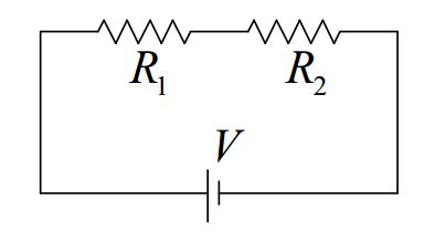
From our viewpoint, the right end of \(R_1\) is connected to the left end of \(R_2\) and nothing else is connected to the point in the circuit where they are connected.
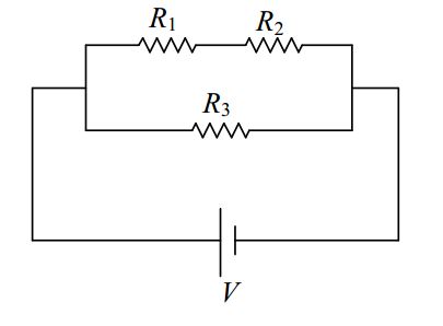
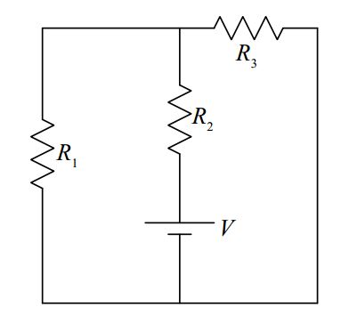
\(R_1\) and \(R_2\) in the following circuit are also in series with each other:
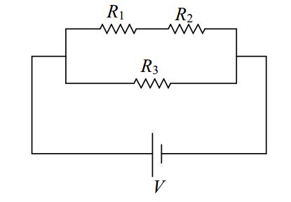
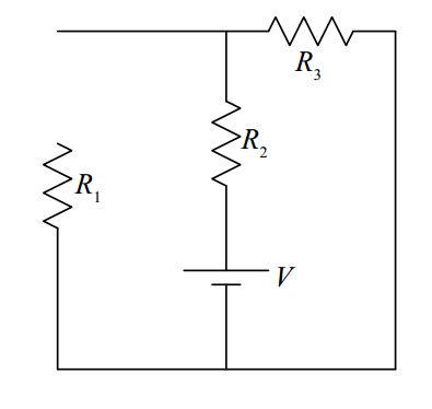
But, \(R_1\) and \(R_2\) in the following circuit are not in series with each other:
While it is true that the right end of \(R_1\) is connected to the left end of \(R_2\), it is not true that “nothing else is connected to the connection.” Indeed, the left end of \(R_3\) is connected to the point in the circuit at which \(R_1\) and \(R_2\) are connected to each other.
In implementing the method of ever simpler circuits, the plan is to replace a combination of resistors that are in series with each other with a single, well-chosen equivalent resistor. The question is, what value must the resistance of the single resistor be in order for it to be equivalent to the set of series resistors it replaces? For now, we simply give you the result. The derivation will be provided in the next chapter.
The equivalent resistance of resistors in series is simply the sum of the resistances.
\[R_S=R_1+R_2+R_3+... \nonumber \]
Resistors in Parallel
Circuit elements are in parallel with each other if they are connected together (by nothing but “perfect” conductor) at both ends. So, for instance, \(R_2\) and \(R_3\) in the following circuit are in parallel with each other.
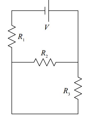
On the other hand, \(R_1\) and \(R_3\) in the following circuit are not in parallel with each other.
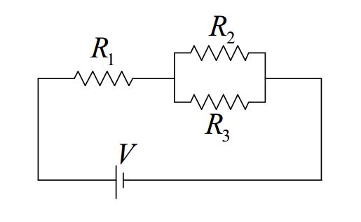
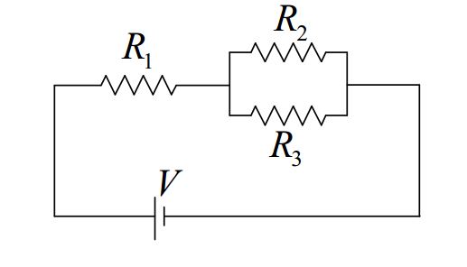
Resistors \(R_2\) and \(R_3\) in the following circuit are in parallel with each other:
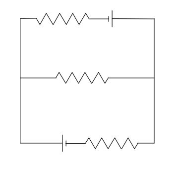
But, none of the resistors in the following circuit are in parallel with each other:
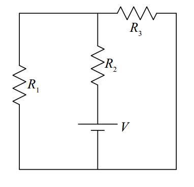
whereas \(R_1\) and \(R_3\) in the following circuit are in parallel with each other:
So what is the equivalent resistor for resistors in parallel? Here we provide the result. We save the derivation for the next chapter.
The equivalent resistance of resistors in parallel is the reciprocal of the sum of the reciprocals of the resistances of the resistors making up the parallel combination:
\[R_P=\frac{1}{\frac{1}{R_1}+\frac{1}{R_2}+\frac{1}{R_3}+.....} \nonumber \]
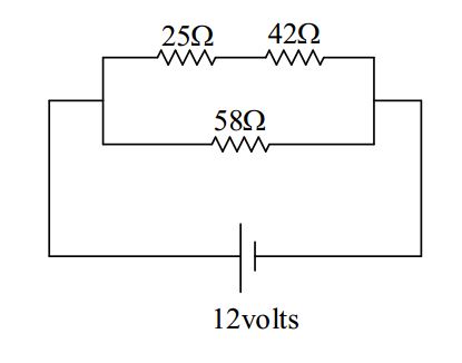
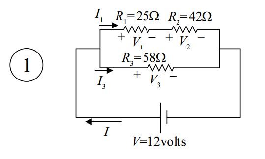
Find the voltage across, and the current through, each of the circuit elements in the diagram
below.
Solution
First we add some notation to the diagram to define our variables (do not omit this step):
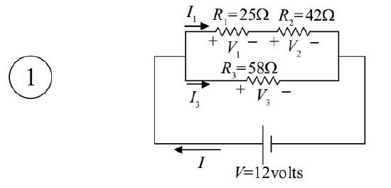
The \(+\) and \(–\) signs on the resistors (indicating the high potential side and the low potential side of each resistor), are an important part of the definition of the voltages. If you are given values, and the value you calculate for V1 turns out to be positive, e.g. \(+5.0\) volts, then the reader of your solution knows that the potential of the left end of \(R_1\) is \(5.0\) volts higher than that of the right end. But, if the value that you calculate for \(V_1\) is negative, e.g. \(-5.0\) volts, then the reader knows that the potential of the left end of \(R_1\) is \(5.0\) volts lower than that of the right end.
The “\(+\)” and “\(–\)” labels on the resistors must be consistent with the current direction. In fact, one first draws and labels the current arrows, and then puts the “\(+\)” on the end of the resister that the current enters (and the “\(–\)” on the other end).
Next we draw a sequence of circuits. Each new diagram includes an equivalent resistor in place of one series combination or one parallel combination. (Do not omit any diagrams, and, do not replace anything more than a single series combination or a single parallel combination of resistors in any one step.) As you draw each circuit, calculate the value of the equivalent resistance.
First, we copy the diagram from the preceding page.

Next, we replace the series combination of \(R_1\) and \(R_2\) with the equivalent resistor \(R_{12}\).
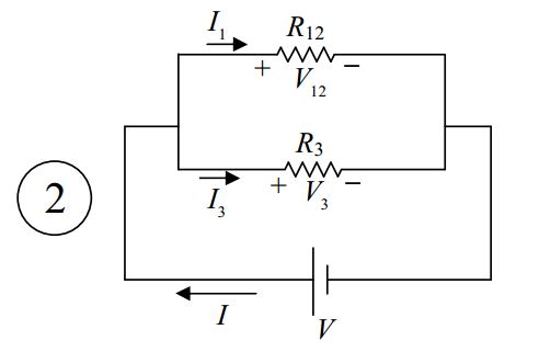
\[R_{12}=R_1+R_2 \nonumber \]
\[R_{12}=25 \Omega+42 \Omega \nonumber \]
\[R_{12}=67 \Omega \nonumber \]
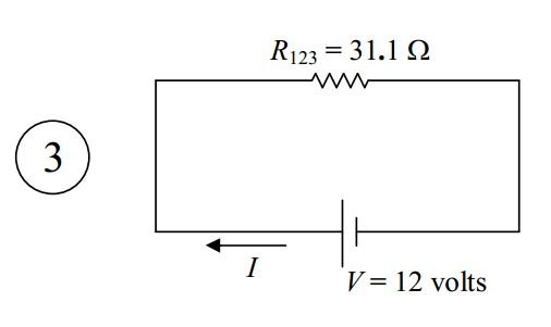
Finally, we replace the parallel combination of \(R_{12}\) and \(R_3\) with the equivalent resistor \(R_{123}\).
\[R_{123}=\frac{1}{\frac{1}{R_{12}}+\frac{1}{R_3}} \nonumber \]
\[R_{123}=\frac{1}{\frac{1}{67 \Omega}+\frac{1}{58 \Omega}} \nonumber \]
\[R_{123}=31.1 \Omega \nonumber \]
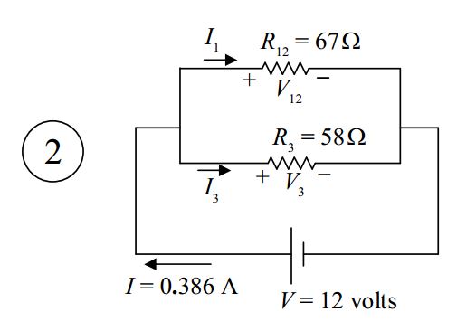
Now we analyze the simplest circuit, the one I have labeled “3” above.
One of the most common mistakes that folks make in analyzing circuits is using any old voltage in \(V =IR\). You have to use the voltage across the resistor. In analyzing circuit 3, however, we can use the one voltage in the diagram because the voltage across the seat of EMF is the voltage across the resistor. The terminals of the resistor are connected to the same two conductors that the terminals of the seat of EMF are connected to. Thus,
\[V=IR_{123} \nonumber \]
\[I=\frac{V}{R_{123}} \nonumber \]
\[I=\frac{12 \mbox{volts}}{31.1 \Omega} \nonumber \]
\[I=0.386A \nonumber \]
At this point, we’ve got two of the answers. The voltage across the seat of EMF was asked for, but it is also given, so we don’t have to show any work for it. And now we have the current through the seat of EMF.
\[V=12 \space\mbox{volts} \nonumber \]
\[I=0.39 \, \mbox{amperes} \nonumber \]
Note that the arrow labeled \(I\) in our diagram is part of our answer. It tells the reader what \(I\) means, including the direction of charge flow for a positive value of \(I\).
Our next step is to take the information that we have learned here, to our next more complicated circuit. That would be the one \(I\) labeled “2” above.
There are only two wires (conductors) in this circuit. I am going to highlight them in order to make my next point:
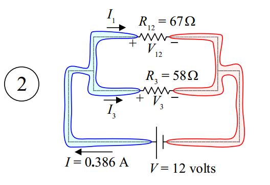
Highlighting the conductors makes it obvious that the voltage across \(R_{12}\) is the same as the voltage across the seat of EMF because, in both cases, the voltage is the potential difference between one and the same pair of conductors. Likewise, the voltage across \(R_3\) is the same as the voltage across the seat of EMF. Hence, we have,
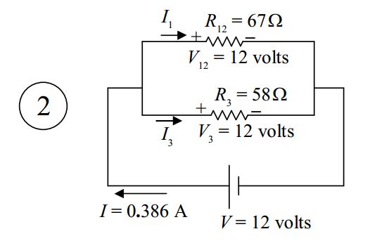
\[V_{12}=V \nonumber \]
\[V_{12}=12 \, \mbox{volts} \nonumber \]
and,
\[V_3=V \nonumber \]
\[V_3=12 \, \mbox{volts} \nonumber \]
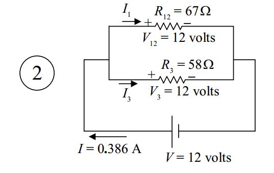
The last value is one of our answers. We were supposed to find \(V_3\). Now that we know the voltage across \(R_3\), we can use it in \(V =IR\) to get \(I_3\).
For resistor \(R_3\), we have:
\[V_3=I_3R_3 \nonumber \]
\[I_3=\frac{V_3}{R_3} \nonumber \]
\[I_3=\frac{12\space \mbox{volts}}{58\Omega} \nonumber \]
\[I_3=0.207 \, A \nonumber \]
The voltage and current through resistor \(R_3\) are answers to the problem:
\[V_3=12 \mbox{volts} \nonumber \]
\[I_3=0.21 \, \mbox{amperes} \nonumber \]
Now let’s get the current through \(R_{12}\). I’ve labeled that current \(I_1\) in diagram 2.
For resistor \(R_{12}\), we have:
\[V_{12}=I_1 R_{12} \nonumber \]
\[I_1=\frac{V_{12}}{R_{12}} \nonumber \]
\[I_1=\frac{12\space \mbox{volts}}{67\space \Omega} \nonumber \]
\[I_1=0.179\space A \nonumber \]
Now it is time to take what we have learned here up to the next more complicated circuit (which is the original circuit).
I copy that here with the values of the current included:
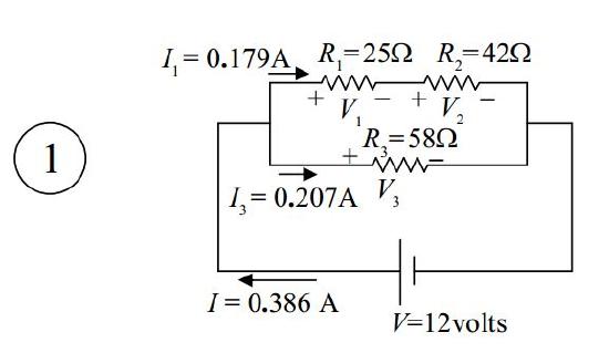
It is clear from this diagram that the current \(I_1\) that we just found (the current through \(R_{12}\)) is the current through \(R_1\), and, it is the current through \(R_2\).
\[I_2=I_1 \nonumber \]
\[I_2=0.179\space A \nonumber \]
These are answers to the problem.
With the current through \(R_1\) known, we can now solve for \(V_1\):
\[V_1=I_1R_1 \nonumber \]
\[V_1=0.179\space (25\Omega) \nonumber \]
\[V_1=4.5 \, \mbox{volts} \nonumber \]
Thus, our answers for resistor \(R_1\) are:
\[V_1=4.5\space \mbox{volts} \nonumber \]
\[I_1=0.18\space \mbox{amperes} \nonumber \]
And, with the current through \(R_2\) known, we can solve for \(V_2\):
\[V_2=I_2R_2 \nonumber \]
\[V_2=0.179\space A(42\Omega) \nonumber \]
\[V_2=7.5\space \mbox{volts} \nonumber \]
Thus, our answers for resistor \(R_2\) are:
\[V_2=7.5\space \mbox{volts} \nonumber \]
\[I_2=0.18\space \mbox{amperes} \nonumber \]
How to Connect a Voltmeter in a Circuit
As discussed earlier in this book, a voltmeter is a device used for measuring the potential difference between two different points in space. In a circuit, we use it to measure the potential difference between two conductors (wires) in the circuit. When you do that, the voltmeter becomes a two-terminal circuit element of the circuit. The ideal voltmeter, as a circuit element, can be considered to be a resistor with infinite resistance. As such, it has no effect on the circuit. This is good. We don’t want the measuring device to change the value of that which you are trying to measure.
A voltmeter consists of a box with two wires coming out of it. Typically, each wire ends in a metal-tipped wand (called a probe) or some kind of metal clip. The box has a gauge on it which displays the potential difference between the two wires. Touch the tip of one wire to one point in the circuit and the tip of the other wire to another point in the circuit (being sure to establish good metal-to-metal contact at both points) and the voltmeter will display the potential difference (the voltage) between those two points in the circuit.
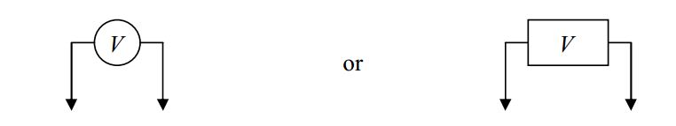
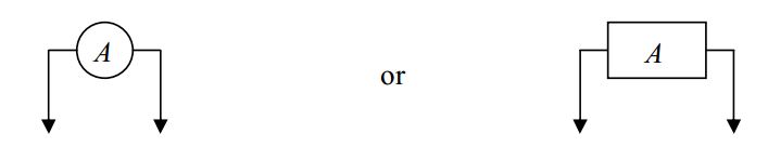
A typical manner of depicting a voltmeter in a circuit is to draw it as
To connect a voltmeter to measure the voltage across \(R_1\) in the following circuit:
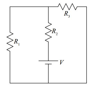
hook it up as indicated in the following diagram.
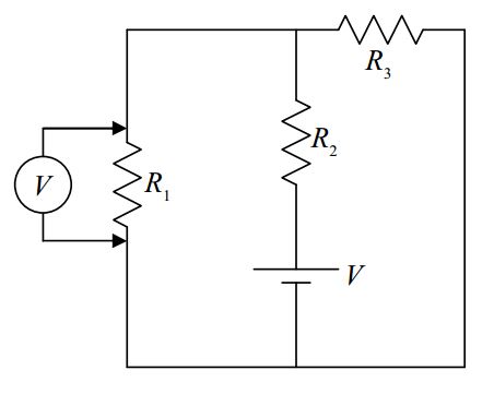
As far as its role as a circuit element (a side effect), the ideal voltmeter has as much effect on the circuit it is used on, as the air around the circuit has.
How to Connect an Ammeter in a Circuit
The ammeter, a device used to measure current, is a totally different beast. The ideal ammeter acts like a perfectly-conducting piece of wire that monitors the charge flow through itself. Connecting it in a circuit as you would a voltmeter (don’t do it!) will drastically change the circuit (and could cause damage to the meter).
A typical manner of depicting an ammeter in a circuit is to draw it as
To connect an ammeter to measure the current in \(R_1\) in the following circuit:
You have to first break the circuit,
and then connect the ammeter in series with the circuit element whose current you wish to measure.
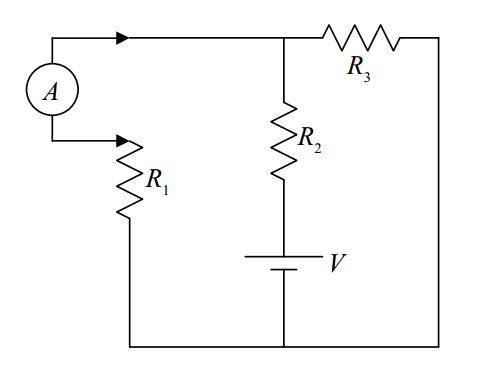
Remember, to measure current with an ammeter, some disassembly is required!