16.4: The Electric Dipole
- Page ID
- 19482
\( \newcommand{\vecs}[1]{\overset { \scriptstyle \rightharpoonup} {\mathbf{#1}} } \)
\( \newcommand{\vecd}[1]{\overset{-\!-\!\rightharpoonup}{\vphantom{a}\smash {#1}}} \)
\( \newcommand{\id}{\mathrm{id}}\) \( \newcommand{\Span}{\mathrm{span}}\)
( \newcommand{\kernel}{\mathrm{null}\,}\) \( \newcommand{\range}{\mathrm{range}\,}\)
\( \newcommand{\RealPart}{\mathrm{Re}}\) \( \newcommand{\ImaginaryPart}{\mathrm{Im}}\)
\( \newcommand{\Argument}{\mathrm{Arg}}\) \( \newcommand{\norm}[1]{\| #1 \|}\)
\( \newcommand{\inner}[2]{\langle #1, #2 \rangle}\)
\( \newcommand{\Span}{\mathrm{span}}\)
\( \newcommand{\id}{\mathrm{id}}\)
\( \newcommand{\Span}{\mathrm{span}}\)
\( \newcommand{\kernel}{\mathrm{null}\,}\)
\( \newcommand{\range}{\mathrm{range}\,}\)
\( \newcommand{\RealPart}{\mathrm{Re}}\)
\( \newcommand{\ImaginaryPart}{\mathrm{Im}}\)
\( \newcommand{\Argument}{\mathrm{Arg}}\)
\( \newcommand{\norm}[1]{\| #1 \|}\)
\( \newcommand{\inner}[2]{\langle #1, #2 \rangle}\)
\( \newcommand{\Span}{\mathrm{span}}\) \( \newcommand{\AA}{\unicode[.8,0]{x212B}}\)
\( \newcommand{\vectorA}[1]{\vec{#1}} % arrow\)
\( \newcommand{\vectorAt}[1]{\vec{\text{#1}}} % arrow\)
\( \newcommand{\vectorB}[1]{\overset { \scriptstyle \rightharpoonup} {\mathbf{#1}} } \)
\( \newcommand{\vectorC}[1]{\textbf{#1}} \)
\( \newcommand{\vectorD}[1]{\overrightarrow{#1}} \)
\( \newcommand{\vectorDt}[1]{\overrightarrow{\text{#1}}} \)
\( \newcommand{\vectE}[1]{\overset{-\!-\!\rightharpoonup}{\vphantom{a}\smash{\mathbf {#1}}}} \)
\( \newcommand{\vecs}[1]{\overset { \scriptstyle \rightharpoonup} {\mathbf{#1}} } \)
\( \newcommand{\vecd}[1]{\overset{-\!-\!\rightharpoonup}{\vphantom{a}\smash {#1}}} \)
\(\newcommand{\avec}{\mathbf a}\) \(\newcommand{\bvec}{\mathbf b}\) \(\newcommand{\cvec}{\mathbf c}\) \(\newcommand{\dvec}{\mathbf d}\) \(\newcommand{\dtil}{\widetilde{\mathbf d}}\) \(\newcommand{\evec}{\mathbf e}\) \(\newcommand{\fvec}{\mathbf f}\) \(\newcommand{\nvec}{\mathbf n}\) \(\newcommand{\pvec}{\mathbf p}\) \(\newcommand{\qvec}{\mathbf q}\) \(\newcommand{\svec}{\mathbf s}\) \(\newcommand{\tvec}{\mathbf t}\) \(\newcommand{\uvec}{\mathbf u}\) \(\newcommand{\vvec}{\mathbf v}\) \(\newcommand{\wvec}{\mathbf w}\) \(\newcommand{\xvec}{\mathbf x}\) \(\newcommand{\yvec}{\mathbf y}\) \(\newcommand{\zvec}{\mathbf z}\) \(\newcommand{\rvec}{\mathbf r}\) \(\newcommand{\mvec}{\mathbf m}\) \(\newcommand{\zerovec}{\mathbf 0}\) \(\newcommand{\onevec}{\mathbf 1}\) \(\newcommand{\real}{\mathbb R}\) \(\newcommand{\twovec}[2]{\left[\begin{array}{r}#1 \\ #2 \end{array}\right]}\) \(\newcommand{\ctwovec}[2]{\left[\begin{array}{c}#1 \\ #2 \end{array}\right]}\) \(\newcommand{\threevec}[3]{\left[\begin{array}{r}#1 \\ #2 \\ #3 \end{array}\right]}\) \(\newcommand{\cthreevec}[3]{\left[\begin{array}{c}#1 \\ #2 \\ #3 \end{array}\right]}\) \(\newcommand{\fourvec}[4]{\left[\begin{array}{r}#1 \\ #2 \\ #3 \\ #4 \end{array}\right]}\) \(\newcommand{\cfourvec}[4]{\left[\begin{array}{c}#1 \\ #2 \\ #3 \\ #4 \end{array}\right]}\) \(\newcommand{\fivevec}[5]{\left[\begin{array}{r}#1 \\ #2 \\ #3 \\ #4 \\ #5 \\ \end{array}\right]}\) \(\newcommand{\cfivevec}[5]{\left[\begin{array}{c}#1 \\ #2 \\ #3 \\ #4 \\ #5 \\ \end{array}\right]}\) \(\newcommand{\mattwo}[4]{\left[\begin{array}{rr}#1 \amp #2 \\ #3 \amp #4 \\ \end{array}\right]}\) \(\newcommand{\laspan}[1]{\text{Span}\{#1\}}\) \(\newcommand{\bcal}{\cal B}\) \(\newcommand{\ccal}{\cal C}\) \(\newcommand{\scal}{\cal S}\) \(\newcommand{\wcal}{\cal W}\) \(\newcommand{\ecal}{\cal E}\) \(\newcommand{\coords}[2]{\left\{#1\right\}_{#2}}\) \(\newcommand{\gray}[1]{\color{gray}{#1}}\) \(\newcommand{\lgray}[1]{\color{lightgray}{#1}}\) \(\newcommand{\rank}{\operatorname{rank}}\) \(\newcommand{\row}{\text{Row}}\) \(\newcommand{\col}{\text{Col}}\) \(\renewcommand{\row}{\text{Row}}\) \(\newcommand{\nul}{\text{Nul}}\) \(\newcommand{\var}{\text{Var}}\) \(\newcommand{\corr}{\text{corr}}\) \(\newcommand{\len}[1]{\left|#1\right|}\) \(\newcommand{\bbar}{\overline{\bvec}}\) \(\newcommand{\bhat}{\widehat{\bvec}}\) \(\newcommand{\bperp}{\bvec^\perp}\) \(\newcommand{\xhat}{\widehat{\xvec}}\) \(\newcommand{\vhat}{\widehat{\vvec}}\) \(\newcommand{\uhat}{\widehat{\uvec}}\) \(\newcommand{\what}{\widehat{\wvec}}\) \(\newcommand{\Sighat}{\widehat{\Sigma}}\) \(\newcommand{\lt}{<}\) \(\newcommand{\gt}{>}\) \(\newcommand{\amp}{&}\) \(\definecolor{fillinmathshade}{gray}{0.9}\)Electric dipoles are a specific combination of a positive charge \(+Q\) held at a fixed distance, \(l\), from an equal and opposite charge, \(-Q\), as illustrated in Figure \(\PageIndex{1}\).

Dipoles can be represented by their “electric dipole vector” (or “electric dipole moment”), \(\vec p\), defined to point in the direction from the negative charge to the positive charge, with magnitude:
\[\begin{aligned} p=Ql\end{aligned}\]
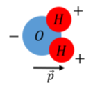
Dipoles arise often in nature, for example, a water molecule can be modeled as a dipole, because the two hydrogen atoms are not symmetrically arranged around the oxygen atom. The electrons in a water molecule tend to stay closer to the oxygen atom, which acquires an excess of 2 electrons, while each proton has a deficit of 1 electron, resulting in a separation of charge (polarization), which can be modeled as a an electric dipole, as in Figure \(\PageIndex{2}\).

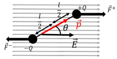
When a dipole is immersed in a uniform electric field, as illustrated in Figure \(\PageIndex{3}\), the net force on the dipole is zero because the force on the positive charge will always be equal and in the opposite direction from the force on the negative charge.

Although the net force on the dipole is zero, there is still a net torque about its center that will cause the dipole to rotate (unless the dipole vector is already parallel to the electric field vector). If the dipole vector makes an angle, \(\theta\), with the electric field vector (as in Figure \(\PageIndex{3}\)), the magnitude of the net torque on the dipole about an axis perpendicular to the page and through the center of the dipole is given by:
\[\begin{aligned} \tau=\frac{l}{2}F^+\sin\theta+\frac{l}{2}F^-\sin\theta=\frac{l}{2}QE\sin\theta+\frac{l}{2}QE\sin\theta=QlE\sin\theta=pE\sin\theta\end{aligned}\]
In Figure \(\PageIndex{3}\), the torque vector is into the page (the forces will make it rotate clockwise), which is the same direction as the cross product, \(\vec p \times \vec E\). Note that the magnitude of the torque is also equal to the magnitude of the cross product. Thus, in general, the torque vector on a dipole, \(\vec p\), from an electric field, \(\vec E\), is given by:
\[\vec\tau = \vec p\times \vec E\]
In particular, note that the torque is zero when the dipole and electric field vectors are parallel. Thus, a dipole will always experience a torque that tends to align it with the electric field vector. The dipole is thus in a stable equilibrium when it is parallel to the electric field.
When an electric dipole is such that its dipole vector is anti-parallel to the electric field vector, the dipole is
- not in equilibrium.
- in a stable equilibrium.
- in an unstable equilibrium.
- Answer
-
C.
We can also model the behavior of the dipole using energy. If a dipole is rotated away from its equilibrium orientation and then released, it will gain (rotational) kinetic energy as it tries to return to equilibrium, and will oscillate about the equilibrium position. When the dipole is held out of equilibrium, we can think of it has having potential energy. To determine the functional form of that potential energy function, we consider the work done in rotating the dipole from an angle \(\theta_1\) to an angle \(\theta_2\) (where the angle is between the dipole and the electric field vectors):
\[\begin{aligned} W&=\int_{\theta_1}^{\theta_2} \tau d\theta=\int_{\theta_1}^{\theta_2} -pE\sin\theta d\theta=-pE\int_{\theta_1}^{\theta_2} \sin\theta d\theta\\[4pt] &=pE[\cos\theta]_{\theta_1}^{\theta_2}=pE\cos\theta_2-pE\cos\theta_1\end{aligned}\]
where the negative sign in the torque is to indicate that the torque is in the opposite direction from increasing \(\theta\) (in Figure \(\PageIndex{3}\), the torque is clockwise whereas the angle \(\theta\) increases counter-clockwise). The net work done in going from position \(\theta_1\) to \(\theta_2\) is the negative of the change in potential energy in going from \(\theta_1\) to \(\theta_2\). Thus, we define the potential energy of an electric dipole, \(\vec p\), in an electric field, \(\vec E\), as:
\[U=-pE\cos\theta =-\vec p\cdot \vec E\]
which has a negative sign, and we also recognize that this is equivalent to the scalar product between \(\vec p\) and \(\vec E\). Note that the negative sign makes sense because systems experience a force/torque that will decrease their potential energy. When the angle is zero, \(\cos\theta=1\), is maximal. Since we need the position with \(\theta=0\) to have the lowest potential energy, the minus sign guarantees that all values of \(\theta\) other than zero will give a potential energy that is higher (greater than \((-1) pE\). Remember that only changes in potential energy are relevant, so the minus sign should not bother you, although you should think about whether it makes sense.

