
19.4: Resistors


- Last updated
- Mar 28, 2024
- Save as PDF
( \newcommand{\kernel}{\mathrm{null}\,}\)
A conductor with current going through it (or current that could go through it) is generally called a “resistor”, to emphasize that charges will experience resistance as they travel through the conductor (as they collide with atoms in the resistor). In this section, we describe resistors, how to combine them, and how to model the heat that is generated when charges collide with the atoms in the resistor.
Resistance
Consider a resistor, with length, L, and cross-sectional area, A, made out of a material with resistivity, ρ, as illustrated in Figure 19.4.1.
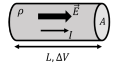
A potential difference, \Delta V, is applied across the length of the resistor, resulting in an electric field, \vec E, within its volume. To good approximation, one can model the two ends of the conductor as parallel plates, so that the magnitude of the electric field throughout the conductor is constant in magnitude and direction and has strength given by:
\begin{aligned} E=\frac{\Delta V}{L}\end{aligned}
Combining this with Ohm’s Law, we have:
\begin{aligned} j&=\sigma E\\[4pt] \therefore j&=\sigma\frac{\Delta V}{L}\\[4pt]\end{aligned}
Since the current density is a microscopic quantity, we can replace it with the current, I, a macroscopic quantity, for the conductor of cross-sectional area, A, to find:
\begin{aligned} j&=\frac{I}{A}\\[4pt] \therefore I&=jA=\sigma\frac{\Delta V}{L}A\end{aligned}
This last equation is often written by isolating the potential difference:
\Delta V=\rho\frac{L}{A}I
where we replaced the inverse of the conductivity with the resistivity. This last equation is the equivalent of Ohm’s Law, but written for a (macroscopic) resistor of length, L, cross-sectional area, A, and made of a material with resistivity, \rho. Written in this way, Ohm’s Law is a statement that the current through a resistor is proportional to the voltage applied across it. The constant of proportionality, R, is called the “resistance”:
\Delta V=RI
This last equation is often called “Ohm’s Law”, even if, technically, Ohm’s Law is the relation between current density and electric field. A resistor is a macroscopic object whose “resistance” can be characterized by a single value, R, its resistance. The resistance of a resistor can be determined from its macroscopic properties (length and cross-sectional area) and from the material from which it is made (with a given resistivity):
R=\rho\frac{L}{A}
The (derived) S.I. unit of resistance is the “Ohm”, (\Omega).
What are the SI units of conductivity?
- \frac{\Omega}{\text{C}}
- \frac{1}{\Omega\text{m}}
- \frac{\text{N}^{2}\Omega}{\text{C}}
- \frac{\text{C}}{\text{s}}
- Answer
-
The model to describe the resistance of a conductor to the flow of electric current under a fixed potential difference, \Delta V, is identical to the model that we derived in Section 15.3 to describe the Poiseuille flow, Q, of an viscous incompressible fluid in a pipe with resistance, R, under a pressure difference, \Delta P:
\begin{aligned} \Delta P = RQ\end{aligned}
Thus, one can think of electric current by analogy to the incompressible flow of a viscous fluid through a pipe. If the pipe is longer, it opposes more resistance to the flow of liquid, just as a longer resistor has a larger resistance to current. A pipe with a larger cross-sectional area has less resistance to the flow of liquid, just as a resistor with a larger cross sectional area, A, has a lower resistance.
Combining resistors
Resistors are the most common component in circuits, and we show below how to model the equivalent resistance of two resistor that are combined in “parallel” or in “series”.
Figure \PageIndex{2} shows two resistors, R_1 and R_2, connected in “series”, to form an an effective resistor with resistance, R_{eff}. A potential difference, \Delta V, is applied across the combination of resistors.
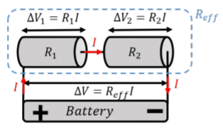
By analogy with fluid mechanics, the charges that enter resistor, R_1, must exit the resistor at the same rate, and then cross the second resistor, R_2. In other words, what comes into R_1 must come back out of R_2, since there is no place for the charges to go. This is the electrical equivalent of “continuity” in fluid mechanics. When resistors are combined in series, both resistors will have the same current, I, through them.
Ohm’s Law (the macroscopic version), must also be true for each resistor:
\begin{aligned} \Delta V_1 &= R_1I\\[4pt] \Delta V_2 &= R_2I\end{aligned}
where, \Delta V_1 and \Delta V_2, are the potential differences across each resistor. \Delta V_1 and \Delta V_2 must sum to \Delta V:
\begin{aligned} \Delta V_1 + \Delta V_2=\Delta V\end{aligned}
since the potential energy (per unit charge) that is lost in each resistor must equal to the total potential energy (per unit charge) that is made available by the battery. Combining this last equation with Ohm’s Law for each resistor, we can model the series combination of resistor as having an “effective resistance”, R_{eff}, given by:
\begin{aligned}\Delta V=\Delta V_{1}+\Delta V_{2}=R_{1}I+R_{2}I=(R_{1}+R_{2})I=R_{eff}I \end{aligned}
R_{eff}=R_{1}+R_{2}\quad\text{(Series resistors)}
It makes sense that the equivalent resistance if found by summing the two resistors, when these are in series. If the two resistors are made of the same material and have the same cross-sectional area, combining them in series is equivalent to fabricating a longer resistor with the two lengths added together. The result is easily extended to any number of resistors:
\begin{aligned} R_{eff}&=R_1+R_2+R_2+\dots\end{aligned}
Figure \PageIndex{3} shows two resistors, with resistances R_1 and R_2, combined in parallel to form an effective resistor with resistance, R_{eff}. A potential difference, \Delta V, is applied across the combination of resistors. When resistors are combined in parallel, both resistors have the same potential difference across them.
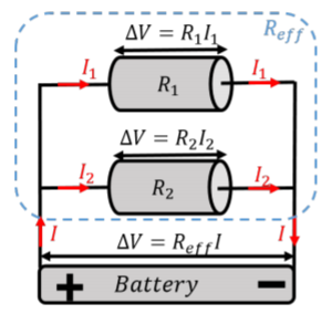
Applying Ohm’s Law to each resistor, we find that they each have difference currents going through them:
\begin{aligned} I_1&=\frac{\Delta V}{R_1}\\[4pt] I_2&=\frac{\Delta V}{R_2}\end{aligned}
The total current, I, that enters the combination of resistors, must also exit the combination of resistor (continuity), so that the total current, I, is the sum of the current through each resistor:
\begin{aligned} I=I_1+I_2\end{aligned}
Combining this with Ohm’s Law, we find:
\begin{aligned} I&=I_1+I_2=\frac{\Delta V}{R_1}+\frac{\Delta V}{R_2}=\left( \frac{1}{R_1}+\frac{1}{R_2} \right)\Delta V\\[4pt] \therefore \Delta V &= \frac{1}{\frac{1}{R_1}+\frac{1}{R_2}}I\end{aligned}
Thus, the effective resistance, R_{eff}, of two resistors connected in parallel is given by:
R_{eff}=\frac{1}{\frac{1}{R_{1}}+\frac{1}{R_{2}}}=\frac{R_{1}R_{2}}{R_{1}+R_{2}}\quad\text{(Parallel resistors)}
where the two forms that are given are equivalent. The effective resistance of two resistors in parallel is smaller than the resistance of either resistor. This makes sense, because combining resistors in parallel is analogous to fabricating a single resistance with a larger cross-sectional area, allowing for “more space” for the charges to flow. Again, this result is easily extended for more than two resistors:
\begin{aligned} R_{eff}=\frac{1}{\frac{1}{R_1}+\frac{1}{R_2}+\frac{1}{R_3}+\dots}\end{aligned}
A R_2=2\Omega resistor is placed in parallel with a R_3=3\Omega resistor and the combination is placed in series with a R_1=1\Omega resistor, as shown in Figure \PageIndex{4}. What is the effective resistance of this combination?
Solution
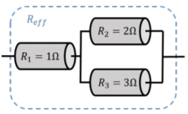
In order to determine the effective resistance of the combination, we can first combine the parallel resistors R_2 and R_3 into an effective resistor, R', which we can then combine in series with the resistor R_1, to obtain the effective resistance of the three resistors. First, combining the parallel resistors, R_2 and R_3, we find:
\begin{aligned} R'=\frac{R_2R_3}{R_2+R_3}=\frac{6}{5}\Omega\end{aligned}
We can then combine this in series with R_1, to obtain the total effective resistance of the combination of three resistors:
\begin{aligned} R_{eff}=R_1+R'=\frac{11}{5}\Omega\end{aligned}
Discussion
In this example, we showed how to determine the effective resistance of a combination of series and parallel resistors. We can determine the effective resistance of complex combinations of resistors in the same manner, by first combining subsets of resistors and then including those with other resistors.
Electrical power dissipated in resistors
As we discussed in Section 19.2, charges that move through a resistor do not gain kinetic energy. Instead, the electric potential energy available from the voltage applied across the resistor is converted into heat, as a result of charges colliding with atoms in the material. The net potential energy, \Delta U, available to a single charge, q, is given by:
\begin{aligned} \Delta U=q\Delta V\end{aligned}
If there are many charges going through the resistor, the rate, P, at which they will dissipate energy in the resistor is given by:
\begin{aligned} P&=\frac{d}{dt}\Delta U=\frac{d}{dt}q\Delta V=I\Delta V\\[4pt] \therefore P&=I\Delta V\end{aligned}
where we recognized that dq/dt=I, is the definition of current. P corresponds to the rate at which energy is dissipated in the resistor, and has dimensions of power. Combining this with Ohm’s Law, the power that is dissipated in a resistor can be written in different ways:
P=I\Delta V=\frac{(\Delta V)^{2}}{R}=I^{2}R
A hair-dryer is rated as consuming 1500\text{W} when connected to an outlet with a 120\text{V} potential difference. What is the resistance of the hair-dryer, and how much current goes through it when it is running?
Solution
Since the power of the hair-dryer and the potential difference across it are known, we can easily determine its resistance:
\begin{aligned} P&=\frac{(\Delta V)^2}{R}\\[4pt] \therefore R&=\frac{(\Delta V)^2}{P}=\frac{(120\text{V})^2}{(1500\text{W})}=9.6\Omega\end{aligned}
Similarly, we can determine the current through the hair dryer:
\begin{aligned} P&=I\Delta V\\[4pt] \therefore I &=\frac{P}{\Delta V}=\frac{(1500\text{W})}{(120\text{V})}=12.5\text{A}\end{aligned}
Discussion
Most household appliances are rated by the electrical power that they consume. This rating assumes that the appliance will be connected to a fixed potential difference (120\text{V} in North America), so it is straightforward to determine the current that they will draw. This is important, because the current that is drawn by the appliance has to go through the wiring in the house, and if the current is too large, the wiring (which has resistance) will heat up (P=I^2R) which could result in an electrical fire. Circuits in a house have safety devices (fuses or breakers) that are designed to interrupt the circuit if the current is too large.
One can rate a power supply, such as a battery, by the amount of power that it can deliver. Power supplies are usually designed to supply a fixed potential difference; for example, a 9\text{V} battery supplies a constant voltage of 9\text{V}. If a small resistor is connected across the terminals of the battery, a large current, I, will flow through the resistor. In principle, the current through the resistor will be given by Ohm’s Law, I=\Delta V/R. However, by reducing the resistance, the current will increase, and the power dissipated by the resistor, P=I\Delta V, would increase indefinitely. Obviously, this is not possible, as it requires the battery to supply energy at the same ever increasing rate. In practice, as the resistance is decreased, the current through the resistor will only increase until I \Delta V is equal to the maximal power that can be dissipated by the battery. As the resistance across the battery is further decreased, the voltage across the battery will start to decrease as well, so that the power dissipated in the resistor, \Delta V I, does not exceed the power that the battery could possibly supply.
Superconductors
Superconductors are materials that, under certain conditions, have zero resistivity. A resistor made from a superconducting material will thus have zero resistance. It is beyond the scope of this textbook to describe how superconductivity arises in materials, however, it is worth knowing that these exist. Typically, superconductivity arises in materials when they are cooled to temperatures close to absolute zero, although some materials exhibit superconductivity at much higher temperatures (\sim 140^{\circ}\text{K} or \sim -130^{\circ}\text{C}). Superconducting materials are often used when one needs a large electric current, such as in a powerful electro-magnet. By having no resistance, a large current can be sustained without dissipating any power.