
2.5: Statics
- Page ID
- 17372

\( \newcommand{\vecs}[1]{\overset { \scriptstyle \rightharpoonup} {\mathbf{#1}} } \)
\( \newcommand{\vecd}[1]{\overset{-\!-\!\rightharpoonup}{\vphantom{a}\smash {#1}}} \)
\( \newcommand{\dsum}{\displaystyle\sum\limits} \)
\( \newcommand{\dint}{\displaystyle\int\limits} \)
\( \newcommand{\dlim}{\displaystyle\lim\limits} \)
\( \newcommand{\id}{\mathrm{id}}\) \( \newcommand{\Span}{\mathrm{span}}\)
( \newcommand{\kernel}{\mathrm{null}\,}\) \( \newcommand{\range}{\mathrm{range}\,}\)
\( \newcommand{\RealPart}{\mathrm{Re}}\) \( \newcommand{\ImaginaryPart}{\mathrm{Im}}\)
\( \newcommand{\Argument}{\mathrm{Arg}}\) \( \newcommand{\norm}[1]{\| #1 \|}\)
\( \newcommand{\inner}[2]{\langle #1, #2 \rangle}\)
\( \newcommand{\Span}{\mathrm{span}}\)
\( \newcommand{\id}{\mathrm{id}}\)
\( \newcommand{\Span}{\mathrm{span}}\)
\( \newcommand{\kernel}{\mathrm{null}\,}\)
\( \newcommand{\range}{\mathrm{range}\,}\)
\( \newcommand{\RealPart}{\mathrm{Re}}\)
\( \newcommand{\ImaginaryPart}{\mathrm{Im}}\)
\( \newcommand{\Argument}{\mathrm{Arg}}\)
\( \newcommand{\norm}[1]{\| #1 \|}\)
\( \newcommand{\inner}[2]{\langle #1, #2 \rangle}\)
\( \newcommand{\Span}{\mathrm{span}}\) \( \newcommand{\AA}{\unicode[.8,0]{x212B}}\)
\( \newcommand{\vectorA}[1]{\vec{#1}} % arrow\)
\( \newcommand{\vectorAt}[1]{\vec{\text{#1}}} % arrow\)
\( \newcommand{\vectorB}[1]{\overset { \scriptstyle \rightharpoonup} {\mathbf{#1}} } \)
\( \newcommand{\vectorC}[1]{\textbf{#1}} \)
\( \newcommand{\vectorD}[1]{\overrightarrow{#1}} \)
\( \newcommand{\vectorDt}[1]{\overrightarrow{\text{#1}}} \)
\( \newcommand{\vectE}[1]{\overset{-\!-\!\rightharpoonup}{\vphantom{a}\smash{\mathbf {#1}}}} \)
\( \newcommand{\vecs}[1]{\overset { \scriptstyle \rightharpoonup} {\mathbf{#1}} } \)
\(\newcommand{\longvect}{\overrightarrow}\)
\( \newcommand{\vecd}[1]{\overset{-\!-\!\rightharpoonup}{\vphantom{a}\smash {#1}}} \)
\(\newcommand{\avec}{\mathbf a}\) \(\newcommand{\bvec}{\mathbf b}\) \(\newcommand{\cvec}{\mathbf c}\) \(\newcommand{\dvec}{\mathbf d}\) \(\newcommand{\dtil}{\widetilde{\mathbf d}}\) \(\newcommand{\evec}{\mathbf e}\) \(\newcommand{\fvec}{\mathbf f}\) \(\newcommand{\nvec}{\mathbf n}\) \(\newcommand{\pvec}{\mathbf p}\) \(\newcommand{\qvec}{\mathbf q}\) \(\newcommand{\svec}{\mathbf s}\) \(\newcommand{\tvec}{\mathbf t}\) \(\newcommand{\uvec}{\mathbf u}\) \(\newcommand{\vvec}{\mathbf v}\) \(\newcommand{\wvec}{\mathbf w}\) \(\newcommand{\xvec}{\mathbf x}\) \(\newcommand{\yvec}{\mathbf y}\) \(\newcommand{\zvec}{\mathbf z}\) \(\newcommand{\rvec}{\mathbf r}\) \(\newcommand{\mvec}{\mathbf m}\) \(\newcommand{\zerovec}{\mathbf 0}\) \(\newcommand{\onevec}{\mathbf 1}\) \(\newcommand{\real}{\mathbb R}\) \(\newcommand{\twovec}[2]{\left[\begin{array}{r}#1 \\ #2 \end{array}\right]}\) \(\newcommand{\ctwovec}[2]{\left[\begin{array}{c}#1 \\ #2 \end{array}\right]}\) \(\newcommand{\threevec}[3]{\left[\begin{array}{r}#1 \\ #2 \\ #3 \end{array}\right]}\) \(\newcommand{\cthreevec}[3]{\left[\begin{array}{c}#1 \\ #2 \\ #3 \end{array}\right]}\) \(\newcommand{\fourvec}[4]{\left[\begin{array}{r}#1 \\ #2 \\ #3 \\ #4 \end{array}\right]}\) \(\newcommand{\cfourvec}[4]{\left[\begin{array}{c}#1 \\ #2 \\ #3 \\ #4 \end{array}\right]}\) \(\newcommand{\fivevec}[5]{\left[\begin{array}{r}#1 \\ #2 \\ #3 \\ #4 \\ #5 \\ \end{array}\right]}\) \(\newcommand{\cfivevec}[5]{\left[\begin{array}{c}#1 \\ #2 \\ #3 \\ #4 \\ #5 \\ \end{array}\right]}\) \(\newcommand{\mattwo}[4]{\left[\begin{array}{rr}#1 \amp #2 \\ #3 \amp #4 \\ \end{array}\right]}\) \(\newcommand{\laspan}[1]{\text{Span}\{#1\}}\) \(\newcommand{\bcal}{\cal B}\) \(\newcommand{\ccal}{\cal C}\) \(\newcommand{\scal}{\cal S}\) \(\newcommand{\wcal}{\cal W}\) \(\newcommand{\ecal}{\cal E}\) \(\newcommand{\coords}[2]{\left\{#1\right\}_{#2}}\) \(\newcommand{\gray}[1]{\color{gray}{#1}}\) \(\newcommand{\lgray}[1]{\color{lightgray}{#1}}\) \(\newcommand{\rank}{\operatorname{rank}}\) \(\newcommand{\row}{\text{Row}}\) \(\newcommand{\col}{\text{Col}}\) \(\renewcommand{\row}{\text{Row}}\) \(\newcommand{\nul}{\text{Nul}}\) \(\newcommand{\var}{\text{Var}}\) \(\newcommand{\corr}{\text{corr}}\) \(\newcommand{\len}[1]{\left|#1\right|}\) \(\newcommand{\bbar}{\overline{\bvec}}\) \(\newcommand{\bhat}{\widehat{\bvec}}\) \(\newcommand{\bperp}{\bvec^\perp}\) \(\newcommand{\xhat}{\widehat{\xvec}}\) \(\newcommand{\vhat}{\widehat{\vvec}}\) \(\newcommand{\uhat}{\widehat{\uvec}}\) \(\newcommand{\what}{\widehat{\wvec}}\) \(\newcommand{\Sighat}{\widehat{\Sigma}}\) \(\newcommand{\lt}{<}\) \(\newcommand{\gt}{>}\) \(\newcommand{\amp}{&}\) \(\definecolor{fillinmathshade}{gray}{0.9}\)When multiple forces act on a body, the (vector) sum of those forces gives the net force, which is the force we substitute in Newton’s second law of motion to get the equation of motion of the body. If all forces sum up to zero, there will be no acceleration, and the body retains whatever velocity it had before. Statics is the study of objects that are neither currently moving nor experiencing a net force, and thus remain stationary. You might expect that this study is easier than the dynamical case when bodies do experience a net force, but that just depends on context. Imagine, for example, a jar filled with marbles: they aren’t moving, but the forces acting on the marbles are certainly not zero, and also not uniformly distributed.
Even if there is no net force, there is no guarantee that an object will exhibit no motion: if the forces are distributed unevenly along an extended object, it may start to rotate. Rotations always happen around a stationary point, known as the pivot. Only a force that has a component perpendicular to the line connecting its point of action to the pivot (the arm) can make an object rotate. The corresponding angular acceleration due to the force depends on both the magnitude of that perpendicular component and the length of the arm,and is known as the moment of the force or the torque \(\tau\). The magnitude of the torque is therefore given by \(Fr sin\theta\), where \(F\) is the magnitude of the force, r the length of the arm, and \(\theta\) the angle between the force and the arm. If we write the arm as a vector r pointing from the pivot to the point where the force acts, we find that the magnitude of the torque equals the cross product of \(r\) and \(F\):
\[\boldsymbol{\tau}=\boldsymbol{r} \times \boldsymbol{F}\]
The direction of rotation can be found by the right-hand rule from the direction of the torque: if the thumb of your right hand points along the direction of \(\tau\), then the direction in which your fingers curve will be the direction in which the object rotates due to the action of the corresponding force \(F\).
We will study rotations in detail in Chapter 5. For now, we’re interested in the case that there is no motion, neither linear nor rotational, which means that the forces and torques acting on our object must satisfy the stability condition: for an extended object to be stationary, both the sum of the forces and the sum of the torques acting on it must be zero.
Example \(\PageIndex{1}\): Suspended Sign
A sign of mass M hangs suspended from a rod of mass m and length \(L\) in a symmetric way and such that the centers of mass of the sign and rod nicely align (Figure \(\PageIndex{1a}\)). One end of the rod is anchored to a wall directly, while the other is supported by a wire with negligible mass that is attached to the same wall a distance h above the anchor.
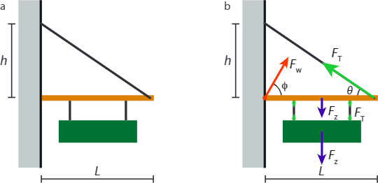
- If the maximum tension the wire can support is T, find the minimum value of h.
- For the case that the tension in the wire equals the maximum tension, find the force (magnitude and direction) exerted by the anchor on the rod.
Solution
(a) We first draw a free-body diagram, Figure \(\PageIndex{1b}\). Force balance on the sign tells us that the tensions in the two lower wires sum to the gravitational force on the sign. The rod is stationary, so we know that the sum of the torques on it must vanish. To get torques, we first need a pivot; we pick the point where the rod is anchored to the wall. We then have three forces contributing a clockwise torque, and one contributing a counterclockwise torque. We’re not told exactly where the wires are attached to the rod, but we are told that the configuration is symmetric and that the center of mass of the sign aligns with that of the rod. Let the first wire be a distance \(\alpha L\) from the wall, and the second a distance \((1-\alpha)L\). The total (clockwise) torque due to the gravitational force on the sign and rod is then given by:
\[\tau_{\mathrm{Z}}=\frac{1}{2} m g L+\frac{1}{2} M g \alpha L+\frac{1}{2} M g(1-\alpha) L=\frac{1}{2}(m+M) g L. \nonumber\]
The counterclockwise torque comes from the tension in the wire, and is given by
\[\frac{1}{2} m g L+\frac{1}{2} M g \alpha L+\frac{1}{2} M g(1-\alpha) L=\frac{1}{2}(m+M) g L. \nonumber\]
Equating the two torques allows us to solve for has a function of \(F_T\), as requested, which gives:
\[h^{2}=\left(\frac{1}{2} \frac{(m+M) g}{F_{\mathrm{T}}}\right)^{2}\left(h^{2}+L^{2}\right) \quad \rightarrow \quad h=\frac{(m+M) g L}{\sqrt{4 F_{\mathrm{T}}^{2}-(m+M)^{2} g^{2}}}\]
We find the minimum value of h by substituting \(F_T=T_{max}\).
(b) As the rod is stationary, all forces on it must cancel. In the horizontal direction, we have the horizontal component of the tension, \(T_{max}\cos \theta\) to the left, which must equal the horizontal component of the force exerted by the wall, \(F_w cos \phi\). In the vertical direction, we have the gravitational force and the two forces from the wires on which the sign hangs in the downward direction, and the vertical component of the tension in the wire in the upward direction, the sum of which must equal the vertical component of the force exerted by the wall (which may point either up or down). We thus have
\[\begin{align*} F_{\mathrm{w}} \cos \phi &=T_{\max } \cos \theta \\[4pt] F_{\mathrm{w}} \sin \phi &=(m+M) g+T_{\max } \sin \theta \end{align*}\]
where \(\tan \theta={h \over L}\) and \(h\) is given in the answer to (a). We find that
\[\begin{align*} F_{\mathrm{w}}^{2} &=T_{\mathrm{max}}^{2}+2(m+M) g T_{\max } \sin \theta+(m+M)^{2} g^{2} \\[4pt] \tan \phi &=\frac{T_{\max } \cos \theta}{(m+M) g+T_{\max } \sin \theta} \end{align*}\]
Note that the above expressions give the complete answer (magnitude and direction). We could eliminate \(h\) and \(\theta\), but that’d just be algebra, leading to more complicated expressions, and not very useful in itself.If we’d been asked to calculate the height or force for any specific values of M, m, and L, we could get the answers easily by substituting the numbers in the expressions given here.