
22.2: AC Circuits
- Page ID
- 15656
\( \newcommand{\vecs}[1]{\overset { \scriptstyle \rightharpoonup} {\mathbf{#1}} } \)
\( \newcommand{\vecd}[1]{\overset{-\!-\!\rightharpoonup}{\vphantom{a}\smash {#1}}} \)
\( \newcommand{\dsum}{\displaystyle\sum\limits} \)
\( \newcommand{\dint}{\displaystyle\int\limits} \)
\( \newcommand{\dlim}{\displaystyle\lim\limits} \)
\( \newcommand{\id}{\mathrm{id}}\) \( \newcommand{\Span}{\mathrm{span}}\)
( \newcommand{\kernel}{\mathrm{null}\,}\) \( \newcommand{\range}{\mathrm{range}\,}\)
\( \newcommand{\RealPart}{\mathrm{Re}}\) \( \newcommand{\ImaginaryPart}{\mathrm{Im}}\)
\( \newcommand{\Argument}{\mathrm{Arg}}\) \( \newcommand{\norm}[1]{\| #1 \|}\)
\( \newcommand{\inner}[2]{\langle #1, #2 \rangle}\)
\( \newcommand{\Span}{\mathrm{span}}\)
\( \newcommand{\id}{\mathrm{id}}\)
\( \newcommand{\Span}{\mathrm{span}}\)
\( \newcommand{\kernel}{\mathrm{null}\,}\)
\( \newcommand{\range}{\mathrm{range}\,}\)
\( \newcommand{\RealPart}{\mathrm{Re}}\)
\( \newcommand{\ImaginaryPart}{\mathrm{Im}}\)
\( \newcommand{\Argument}{\mathrm{Arg}}\)
\( \newcommand{\norm}[1]{\| #1 \|}\)
\( \newcommand{\inner}[2]{\langle #1, #2 \rangle}\)
\( \newcommand{\Span}{\mathrm{span}}\) \( \newcommand{\AA}{\unicode[.8,0]{x212B}}\)
\( \newcommand{\vectorA}[1]{\vec{#1}} % arrow\)
\( \newcommand{\vectorAt}[1]{\vec{\text{#1}}} % arrow\)
\( \newcommand{\vectorB}[1]{\overset { \scriptstyle \rightharpoonup} {\mathbf{#1}} } \)
\( \newcommand{\vectorC}[1]{\textbf{#1}} \)
\( \newcommand{\vectorD}[1]{\overrightarrow{#1}} \)
\( \newcommand{\vectorDt}[1]{\overrightarrow{\text{#1}}} \)
\( \newcommand{\vectE}[1]{\overset{-\!-\!\rightharpoonup}{\vphantom{a}\smash{\mathbf {#1}}}} \)
\( \newcommand{\vecs}[1]{\overset { \scriptstyle \rightharpoonup} {\mathbf{#1}} } \)
\(\newcommand{\longvect}{\overrightarrow}\)
\( \newcommand{\vecd}[1]{\overset{-\!-\!\rightharpoonup}{\vphantom{a}\smash {#1}}} \)
\(\newcommand{\avec}{\mathbf a}\) \(\newcommand{\bvec}{\mathbf b}\) \(\newcommand{\cvec}{\mathbf c}\) \(\newcommand{\dvec}{\mathbf d}\) \(\newcommand{\dtil}{\widetilde{\mathbf d}}\) \(\newcommand{\evec}{\mathbf e}\) \(\newcommand{\fvec}{\mathbf f}\) \(\newcommand{\nvec}{\mathbf n}\) \(\newcommand{\pvec}{\mathbf p}\) \(\newcommand{\qvec}{\mathbf q}\) \(\newcommand{\svec}{\mathbf s}\) \(\newcommand{\tvec}{\mathbf t}\) \(\newcommand{\uvec}{\mathbf u}\) \(\newcommand{\vvec}{\mathbf v}\) \(\newcommand{\wvec}{\mathbf w}\) \(\newcommand{\xvec}{\mathbf x}\) \(\newcommand{\yvec}{\mathbf y}\) \(\newcommand{\zvec}{\mathbf z}\) \(\newcommand{\rvec}{\mathbf r}\) \(\newcommand{\mvec}{\mathbf m}\) \(\newcommand{\zerovec}{\mathbf 0}\) \(\newcommand{\onevec}{\mathbf 1}\) \(\newcommand{\real}{\mathbb R}\) \(\newcommand{\twovec}[2]{\left[\begin{array}{r}#1 \\ #2 \end{array}\right]}\) \(\newcommand{\ctwovec}[2]{\left[\begin{array}{c}#1 \\ #2 \end{array}\right]}\) \(\newcommand{\threevec}[3]{\left[\begin{array}{r}#1 \\ #2 \\ #3 \end{array}\right]}\) \(\newcommand{\cthreevec}[3]{\left[\begin{array}{c}#1 \\ #2 \\ #3 \end{array}\right]}\) \(\newcommand{\fourvec}[4]{\left[\begin{array}{r}#1 \\ #2 \\ #3 \\ #4 \end{array}\right]}\) \(\newcommand{\cfourvec}[4]{\left[\begin{array}{c}#1 \\ #2 \\ #3 \\ #4 \end{array}\right]}\) \(\newcommand{\fivevec}[5]{\left[\begin{array}{r}#1 \\ #2 \\ #3 \\ #4 \\ #5 \\ \end{array}\right]}\) \(\newcommand{\cfivevec}[5]{\left[\begin{array}{c}#1 \\ #2 \\ #3 \\ #4 \\ #5 \\ \end{array}\right]}\) \(\newcommand{\mattwo}[4]{\left[\begin{array}{rr}#1 \amp #2 \\ #3 \amp #4 \\ \end{array}\right]}\) \(\newcommand{\laspan}[1]{\text{Span}\{#1\}}\) \(\newcommand{\bcal}{\cal B}\) \(\newcommand{\ccal}{\cal C}\) \(\newcommand{\scal}{\cal S}\) \(\newcommand{\wcal}{\cal W}\) \(\newcommand{\ecal}{\cal E}\) \(\newcommand{\coords}[2]{\left\{#1\right\}_{#2}}\) \(\newcommand{\gray}[1]{\color{gray}{#1}}\) \(\newcommand{\lgray}[1]{\color{lightgray}{#1}}\) \(\newcommand{\rank}{\operatorname{rank}}\) \(\newcommand{\row}{\text{Row}}\) \(\newcommand{\col}{\text{Col}}\) \(\renewcommand{\row}{\text{Row}}\) \(\newcommand{\nul}{\text{Nul}}\) \(\newcommand{\var}{\text{Var}}\) \(\newcommand{\corr}{\text{corr}}\) \(\newcommand{\len}[1]{\left|#1\right|}\) \(\newcommand{\bbar}{\overline{\bvec}}\) \(\newcommand{\bhat}{\widehat{\bvec}}\) \(\newcommand{\bperp}{\bvec^\perp}\) \(\newcommand{\xhat}{\widehat{\xvec}}\) \(\newcommand{\vhat}{\widehat{\vvec}}\) \(\newcommand{\uhat}{\widehat{\uvec}}\) \(\newcommand{\what}{\widehat{\wvec}}\) \(\newcommand{\Sighat}{\widehat{\Sigma}}\) \(\newcommand{\lt}{<}\) \(\newcommand{\gt}{>}\) \(\newcommand{\amp}{&}\) \(\definecolor{fillinmathshade}{gray}{0.9}\)learning objectives
- Describe properties of an inductor
Inductance
OVERVIEW
Induction is the process in which an emf is induced by changing magnetic flux. Specifically in the case of electronics, inductance is the property of a conductor by which a change in current in the conductor creates a voltage in both the conductor itself (self-inductance) and any nearby conductors (mutual inductance). This effect derives from two fundamental observations of physics: First, that a steady current creates a steady magnetic field and second, that a time-varying magnetic field induces a voltage in a nearby conductor (Faraday’s law of induction). From Lenz’s law, a changing electric current through a circuit that has inductance induces a proportional voltage which opposes the change in current (if this wasn’t true one can easily see how energy could not be conserved, with a changing current reinforcing the change in a positive feedback loop).
MUTUAL INDUCTANCE
Mutual inductance is the effect of Faraday’s law of induction for one device upon another, such as the primary coil in transmitting energy to the secondary in a transformer. See, where simple coils induce emfs in one another.
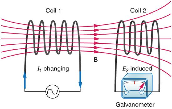
Mutual Inductance in Coils: These coils can induce emfs in one another like an inefficient transformer. Their mutual inductance M indicates the effectiveness of the coupling between them. Here a change in current in coil 1 is seen to induce an emf in coil 2. (Note that “E2 induced” represents the induced emf in coil 2. )
In the many cases where the geometry of the devices is fixed, flux is changed by varying current. We therefore concentrate on the rate of change of current, ΔI/Δt, as the cause of induction. A change in the current I1 in one device, coil 1 in the figure, induces an emf2 in the other. We express this in equation form as
\[\mathrm { emf } _ { 2 } = - \mathrm { M } \dfrac { \Delta \mathrm { I } _ { 1 } } { \Delta \mathrm { t } } \]
where M is defined to be the mutual inductance between the two devices. The minus sign is an expression of Lenz’s law. The larger the mutual inductance M, the more effective the coupling. Units for M are (V⋅s)/A=Ωs, which is named a henry (H), after Joseph Henry (discovered of self-inductance). That is, 1 H=1Ωs.
Nature is symmetric here. If we change the current I2 in coil 2, we induce an emf1 in coil 1, which is given by
\[\mathrm { emf } _ { 1 } = - \mathrm { M } \dfrac { \Delta \mathrm { I } _ { 2 } } { \Delta \mathrm { t } }\]
where M is the same as for the reverse process. Transformers run backward with the same effectiveness, or mutual inductance M.
A large mutual inductance M may or may not be desirable. We want a transformer to have a large mutual inductance. But an appliance, such as an electric clothes dryer, can induce a dangerous emf on its case if the mutual inductance between its coils and the case is large. One way to reduce mutual inductance M is to counterwind coils to cancel the magnetic field produced. (See ).
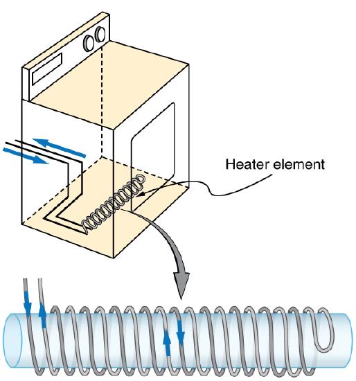
Counterwinding: The heating coils of an electric clothes dryer can be counter-wound so that their magnetic fields cancel one another, greatly reducing the mutual inductance with the case of the dryer.
SELF-INDUCTANCE
Self-inductance, the effect of Faraday’s law of induction of a device on itself, also exists. When, for example, current through a coil is increased, the magnetic field and flux also increase, inducing a counter emf, as required by Lenz’s law. Conversely, if the current is decreased, an emf is induced that opposes the decrease. Most devices have a fixed geometry, and so the change in flux is due entirely to the change in current ΔI through the device. The induced emf is related to the physical geometry of the device and the rate of change of current. It is given by
\[\mathrm { emf } = - \mathrm { L } \dfrac { \Delta \mathrm { I } } { \Delta \mathrm{t} }\]
where L is the self-inductance of the device. A device that exhibits significant self-inductance is called an inductor, and given the symbol in.
Inductor Symbol
The minus sign is an expression of Lenz’s law, indicating that emf opposes the change in current. Units of self-inductance are henries (H) just as for mutual inductance. The larger the self-inductance L of a device, the greater its opposition to any change in current through it. For example, a large coil with many turns and an iron core has a large L and will not allow current to change quickly. To avoid this effect, a small L must be achieved, such as by counterwinding coils as in.
SOLENOIDS
It is possible to calculate L for an inductor given its geometry (size and shape) and knowing the magnetic field that it produces. This is difficult in most cases, because of the complexity of the field created. The inductance L is usually a given quantity. One exception is the solenoid, because it has a very uniform field inside, a nearly zero field outside, and a simple shape. The self-inductance of a solenoid of cross-sectional area A and length ℓ is
\[\mathrm { L } = \frac { \mu _ { 0 } \mathrm { N } ^ { 2 } \mathrm { A } } { l } \mathrm{ (solenoid)}.\]
It is instructive to derive this equation, but this is left as an exercise to the reader. (Hint: start by noting that the induced emf is given by Faraday’s law of induction as emf=−N(Δ/Δt) and, by the definition of self-inductance is given as as emf=−L(ΔI//Δt) and equate these two expressions). Note that the inductance depends only on the physical characteristics of the solenoid, consistent with its definition.
RL Circuits
An RL circuit consists of an inductor and a resistor, in series or parallel with each other, with current driven by a voltage source.
learning objectives
- Describe current-voltage relationship in the RL circuit and calculate energy that can be stored in an inductor
RL Circuits
A resistor-inductor circuit (RL circuit) consists of a resistor and an inductor (either in series or in parallel ) driven by a voltage source.
Review
Recall that induction is the process in which an emf is induced by changing magnetic flux. Mutual inductance is the effect of Faraday’s law of induction for one device upon another, while self-inductance is the the effect of Faraday’s law of induction of a device on itself. An inductor is a device or circuit component that exhibits self-inductance.
Energy of an Inductor
We know from Lenz’s law that inductors oppose changes in current. We can think of this situation in terms of energy. Energy is stored in a magnetic field. It takes time to build up energy, and it also takes time to deplete energy; hence, there is an opposition to rapid change. In an inductor, the magnetic field is directly proportional to current and to the inductance of the device. It can be shown that the energy stored in an inductor Eind is given by:
\[\mathrm { E } _ { \mathrm { ind } } = \dfrac { 1 } { 2 } \mathrm { LI } ^ { 2 }\]
Inductors in Circuits
We know that the current through an inductor L cannot be turned on or off instantaneously. The change in current changes the magnetic flux, inducing an emf opposing the change (Lenz’s law). How long does the opposition last? Current will flow and can be turned off, but how long does it take? The following figure shows a switching circuit that can be used to examine current through an inductor as a function of time.
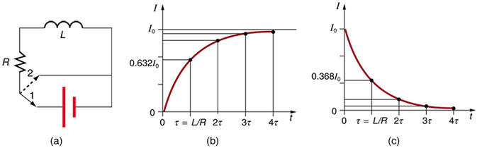
Current in an RL Circuit: (a) An RL circuit with a switch to turn current on and off. When in position 1, the battery, resistor, and inductor are in series and a current is established. In position 2, the battery is removed and the current eventually stops because of energy loss in the resistor. (b) A graph of current growth versus time when the switch is moved to position 1. (c) A graph of current decay when the switch is moved to position 2.
When the switch is first moved to position 1 (at t=0), the current is zero and it eventually rises to I0=V/R, where R is the total resistance of the circuitand V is the battery ‘s voltage. The opposition of the inductor L is greatest at the beginning, because the change in current is greatest at that time. The opposition it poses is in the form of an induced emf, which decreases to zero as the current approaches its final value. This is the hallmark of an exponential behavior, and it can be shown (with calculus) that
\[\mathrm { I } = \mathrm { I } _ { 0 } \left( 1 - \mathrm { e } ^ { \dfrac { - t } { \tau } } \right)\]
is the current in an RL circuit when switched on. (Note the similarity to the exponential behavior of the voltage on a charging capacitor.) The initial current is zero and approaches I0=V/R with a characteristic time constant for an RL circuit, given by:
\[\tau = \dfrac { \mathrm { L } } { \mathrm { R } }\]
where ττ has units of seconds, since 1H=1Ω⋅s1H=1Ω⋅s. In the first period of time ττ, the current rises from zero to 0.632I0, since I=I0(1−e−1)=I0(1−0.368)=0.632I0. The current will be 0.632 of the remainder in the next time. A well-known property of the exponential function is that the final value is never exactly reached, but 0.632 of the remainder to that value is achieved in every characteristic time ττ. In just a few multiples of the time ττ, the final value is very nearly achieved (see part (b) of above figure).
The characteristic time ττ depends on only two factors, the inductance L and the resistance R. The greater the inductance L, the greater it is, which makes sense since a large inductance is very effective in opposing change. The smaller the resistance R, the greater ττ is. Again this makes sense, since a small resistance means a large final current and a greater change to get there. In both cases (large Land small R) more energy is stored in the inductor and more time is required to get it in and out.
When the switch in (a) is moved to position 2 and cuts the battery out of the circuit, the current drops because of energy dissipation by the resistor. However, this is also not instantaneous, since the inductor opposes the decrease in current by inducing an emf in the same direction as the battery that drove the current. Furthermore, there is a certain amount of energy, (1/2)LI02, stored in the inductor, and it is dissipated at a finite rate. As the current approaches zero, the rate of decrease slows, since the energy dissipation rate is I2R. Once again the behavior is exponential, and I is found to be
\[\mathrm { I } = \mathrm { I } _ { 0 } \mathrm { e } ^ { \frac { - t } { \tau } }\]
In (c), in the first period of time τ=L/Rτ=L/R after the switch is closed, the current falls to 0.368 of its initial value, since I=I0e−1=0.368I0. In each successive time ττ, the current falls to 0.368 of the preceding value, and in a few multiples of ττ, the current becomes very close to zero.
RLC Series Circuit: At Large and Small Frequencies; Phasor Diagram
Response of an RLC circuit depends on the driving frequency—at large enough frequencies, inductive (capacitive) term dominates.
learning objectives
- Distinguish behavior of RLC series circuits as large and small frequencies
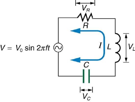
In previous Atoms we learned how an RLC series circuit, as shown in, responds to an AC voltage source. By combining Ohm’s law (Irms=Vrms/Z; Irms and Vrms are rms current and voltage) and the expression for impedance Z, from:
Series RLC Circuit: A series RLC circuit: a resistor, inductor and capacitor (from left).
\[\mathrm { Z } = \sqrt { \mathrm { R } ^ { 2 } + \left( \mathrm { X } _ { \mathrm { L } } - \mathrm { X } _ { \mathrm { C } } \right) ^ { 2 } } \left( \mathrm { X } _ { \mathrm { L } } = 2 \pi \nu \mathrm { L } , \mathrm { X } _ { \mathrm { C } } = \dfrac { 1 } { 2 \pi \nu C } \right)\]
we arrived at: \(\mathrm { I } _ { \mathrm { rms } } = \frac { \mathrm { V } _ { \mathrm { rms } } } { \sqrt { \mathrm { R } ^ { 2 } + \left( \mathrm { X } _ { \mathrm { L } } - \mathrm { X } _ { \mathrm { C } } \right) ^ { 2 } } }\).
From the equation, we studied resonance conditions for the circuit. We also learned the phase relationships among the voltages across resistor, capacitor and inductor: when a sinusoidal voltage is applied, the current lags the voltage by a 90º phase in a circuit with an inductor, while the current leads the voltage by 90∘ in a circuit with a capacitor. Now, we will examine the system’s response at limits of large and small frequencies.
At Large Frequencies
At large enough frequencies (\(\nu \gg \frac { 1 } { \sqrt { 2 \pi \mathrm { LC } } }\)), XL is much greater than XC. If the frequency is high enough that XL is much larger than R as well, the impedance Z is dominated by the inductive term. When \(\mathrm{Z≈X_{L}}\), the circuit is almost equivalent to an AC circuit with just an inductor. Therefore, the rms current will be Vrms/XL, and the current lags the voltage by almost 90∘. This response makes sense because, at high frequencies, Lenz’s law suggests that the impedance due to the inductor will be large.
At Small Frequencies
The impedance Z at small frequencies (\(\nu \ll \frac { 1 } { \sqrt { 2 \pi \mathrm { LC } } }\)) is dominated by the capacitive term, assuming that the frequency is high enough so that XC is much larger than R. When \(\mathrm{Z≈X_C}\), the circuit is almost equivalent to an AC circuit with just a capacitor. Therefore, the rms current will be given as Vrms/XC, and the current leads the voltage by almost 90∘.
Resistors in AC Circuits
In a circuit with a resistor and an AC power source, Ohm’s law still applies (V = IR).
learning objectives
- Apply Ohm’s law to determine current and voltage in an AC circuit
Direct current (DC) is the flow of electric charge in only one direction. It is the steady state of a constant-voltage circuit. Most well known applications, however, use a time-varying voltage source. Alternating current (AC) is the flow of electric charge that periodically reverses direction. If the source varies periodically, particularly sinusoidally, the circuit is known as an alternating-current circuit. Examples include the commercial and residential power that serves so many of our needs. shows graphs of voltage and current versus time for typical DC and AC power. The AC voltages and frequencies commonly used in homes and businesses vary around the world.
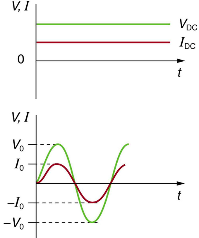
Sinusoidal Voltage and Current: (a) DC voltage and current are constant in time, once the current is established. (b) A graph of voltage and current versus time for 60-Hz AC power. The voltage and current are sinusoidal and are in phase for a simple resistance circuit. The frequencies and peak voltages of AC sources differ greatly.
We have studied Ohm’s law:
\[\mathrm { I } = \dfrac { \mathrm { V } } { \mathrm { R } }\]
where I is the current, V is the voltage, and R is the resistance of the circuit. Ohm’s law applies to AC circuits as well as to DC circuits. Therefore, with an AC voltage given by:
\[\mathrm { V } = \mathrm { V } _ { 0 } \sin ( 2 \pi \nu \mathrm { t } )\]
where V0 is the peak voltage and νν is the frequency in hertz, the current in the circuit is given as:
\[\mathrm { I } = \dfrac { \mathrm { V } _ { 0 } } { \mathrm { R } } \sin ( 2 \pi \nu t )\]
In this example, in which we have a resistor and the voltage source in the circuit, the voltage and current are said to be in phase, as seen in (b). Current in the resistor alternates back and forth without any phase difference, just like the driving voltage.
Consider a perfect resistor that brightens and dims 120 times per second as the current repeatedly goes through zero. (A 120-Hz flicker is too rapid for your eyes to detect. ) The fact that the light output fluctuates means that the power is fluctuating. Since the power supplied is P = IV, if we use the above expressions for I and V, we see that the time dependence of power is:
\[\mathrm { P } = \dfrac { \mathrm { V } _ { 0 } ^ { 2 } } { \mathrm { R } } \cdot \sin ( 2 \pi \nu \mathrm { t } )\]
To find the average power consumed by this circuit, we need to take the time average of the function. Since:
\[\dfrac { 1 } { \pi } \int _ { 0 } ^ { \pi } \sin ^ { 2 } ( \mathrm { x } ) \mathrm { d } \mathrm { x } = \dfrac { 1 } { 2 }\]
we see that:
\[\mathrm { P } _ { \mathrm { avg } } = \dfrac { \mathrm { V } _ { 0 } ^ { 2 } } { 2 \mathrm { R } }\]
Capacitors in AC Circuits: Capacitive Reactance and Phasor Diagrams
The voltage across a capacitor lags the current. Due to the phase difference, it is useful to introduce phasors to describe these circuits.
learning objectives
- Explain the benefits of using a phasor representation
In the previous Atom on “Resistors in AC Circuits”, we introduced an AC power source and studied how resistors behave in AC circuits. There, we used the Ohm’s law (V=IR) to derive the relationship between voltage and current in AC circuits. In this and following Atoms, we will generalize the Ohm’s law so that we can use it even when we have capacitors and inductors in the circuit. To get there, we will first introduce a very general, pictorial way of representing a sinusoidal wave, using phasor.
Capacitors in AC Circuits with Phasors
Phasor
The key idea in the phasor representation is that a complex, time-varying signal may be represented as the product of a complex number (that is independent of time) and a complex signal (that is dependent on time). Phasors separate the dependencies on A (amplitude), νν ( frequency ), and θ ( phase ) into three independent factors. This can be particularly useful because the frequency factor (which includes the time-dependence of the sinusoid) is often common to all the components of a linear combination of sinusoids. In those situations, phasors allow this common feature to be factored out, leaving just the A and θ features. For example, we can represent \(\mathrm { A } \cdot \cos ( 2 \pi \nu t + \theta )\) simply as a complex constant, \(\mathrm{A e ^ { i \theta }}\). Since phasors are represented by a magnitude (or modulus) and an angle, it is pictorially represented by a rotating arrow (or a vector) in x-y plane.
Fig 3: A phasor can be seen as a vector rotating about the origin in a complex plane. The cosine function is the projection of the vector onto the real axis. Its amplitude is the modulus of the vector, and its argument is the total phase \omega t+\theta. The phase constant \theta represents the angle that the vector forms with the real axis at t = 0.
Capacitors in AC circuits
Earlier in a previous Atom, we studied how the voltage and the current varied with time. If the AC supply is connected to a resistor, then the current and voltage will be proportional to each other. This means that the current and voltage will “peak” at the same time. We say that the current and voltage are in phase.
When a capacitor is connected to an alternating voltage, the maximum voltage is proportional to the maximum current, but the maximum voltage does not occur at the same time as the maximum current. The current has its maximum (it peaks) one quarter of a cycle before the voltage peaks. Engineers say that the “current leads the voltage by 90∘“. This is shown in.
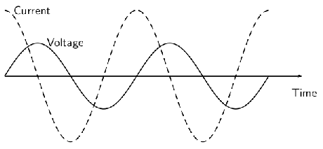
Fig 2: The current peaks (has its maximum) one quarter of a wave before the voltage when a capacitor is connected to an alternating voltage.
For a circuit with a capacitor, the instantaneous value of V/I is not constant. However, the value of Vmax/Imax is useful, and is called the capacitive reactance (XC) of the component. Because it is still a voltage divided by a current (like resistance ), its unit is the ohm. The value of XC (C standing for capacitor) depends on its capacitance (C) and the frequency (f) of the alternating current. \(\mathrm { X } _ { \mathrm { C } } = \frac { 1 } { 2 \pi \nu \mathrm { C } }\).
The capacitor is affecting the current, having the ability to stop it altogether when fully charged. Since an AC voltage is applied, there is an rms current, but it is limited by the capacitor. This is considered to be an effective resistance of the capacitor to AC, and so the rms current Irms in the circuit containing only a capacitor C is given by another version of Ohm’s law to be \(\mathrm { I } _ { \mathrm { rms } } = \frac { \mathrm { V } _ { \mathrm { rms } } } { \mathrm { X } _ { \mathrm { C } } }\), where Vrms is the rms voltage. Note that XC replaces R in the DC version of the Ohm’s law.
Phase representation
Since the voltage across a capacitor lags the current, the phasor representing the current and voltage would be give as in. In the diagram, the arrows rotate in counter-clockwise direction at a frequency νν. (Therefore, current leads voltage. ) In the following Atoms, we will see how these phasors can be used to analyze RC, RL, LC, and RLC circuits.
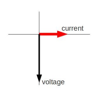
Fig 4: Phasor diagram for an AC circuit with a capacitor
Inductors in AC Circuits: Inductive Reactive and Phasor Diagrams
In an AC circuit with an inductor, the voltage across an inductor “leads” the current because of the Lenz’ law.
learning objectives
- Explain why the voltage across an inductor “leads” the current in an AC circuit with an inductor
Suppose an inductor is connected directly to an AC voltage source, as shown in. It is reasonable to assume negligible resistance because in practice we can make the resistance of an inductor so small that it has a negligible effect on the circuit. The graph shows voltage and current as functions of time. (b) starts with voltage at a maximum. Note that the current starts at zero, then rises to its peak after the voltage driving it (as seen in the preceding section when DC voltage was switched on).
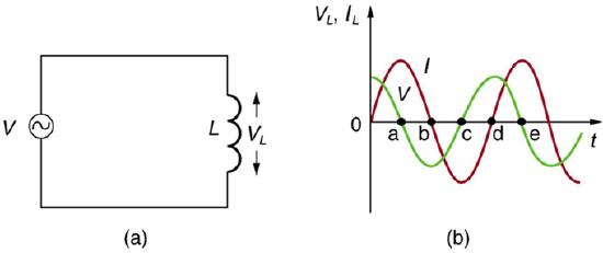
AC Voltage Source in Series with an Inductor: (a) An AC voltage source in series with an inductor having negligible resistance. (b) Graph of current and voltage across the inductor as functions of time.
When the voltage becomes negative at point a, the current begins to decrease; it becomes zero at point b, where voltage is its most negative. The current then becomes negative, again following the voltage. The voltage becomes positive at point c where it begins to make the current less negative. At point d, the current goes through zero just as the voltage reaches its positive peak to start another cycle. Hence, when a sinusoidal voltage is applied to an inductor, the voltage leads the current by one-fourth of a cycle, or by a 90º phase angle.
Current lags behind voltage, since inductors oppose change in current. Changing current induces an emf. This is considered an effective resistance of the inductor to AC. The rms current Irms through an inductor L is given by a version of Ohm’s law: \(\mathrm { I } _ { \mathrm { rms } } = \frac { \mathrm { V } _ { \mathrm { rms } } } { \mathrm { X } _ { \mathrm { L } } }\) where Vrms is the rms voltage across the inductor and \(\mathrm { X } _ { \mathrm { L } } = 2 \pi \nu \mathrm { L }\) with \(\nu\) the frequency of the AC voltage source in hertz. XL is called the inductive reactance. Because the inductor reacts to impede the current, XLhas units of ohms (1 H=1 Ωs, so that frequency times inductance has units of (cycles/s)(Ωs)=Ω), consistent with its role as an effective resistance.
Phasor Representation
The voltage across an inductor “leads” the current because of the Lenz’s law. Therefore, the phasor representing the current and voltage would be given as in. Again, the phasors are vectors rotating in counter-clockwise direction at a frequency \(\nu\) (you can see that the voltage leads the current). Subsequent Atoms will discuss how these phasors can be used to analyze RC, RL, LC, and RLC circuits.
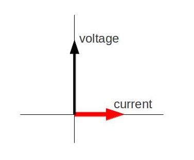
Phasor Diagram: Phasor diagram for an AC circuit with an inductor.
Phasors for Inductors in AC Circuits
Resonance in RLC Circuits
Resonance is the tendency of a system to oscillate with greater amplitude at some frequencies—in an RLC series circuit, it occurs at \(\nu _ { 0 } = \frac { 1 } { 2 \pi \sqrt { \mathrm{L C} }\) } .
learning objectives
- Compare resonance characteristics of higher- and lower-resistance circuits
Resonance is the tendency of a system to oscillate with greater amplitude at some frequencies than at others. Frequencies at which the response amplitude is a relative maximum are known as the system’s resonance frequencies. To study the resonance in an RLC circuit, as illustrated below, we can see how the circuit behaves as a function of the frequency of the driving voltage source.
RLC Series Circuit: An RLC series circuit with an AC voltage source. f is the frequency of the source.
Combining Ohm ‘s law, Irms=Vrms/Z, and the expression for impedance Z from
\(\mathrm { Z } = \sqrt { \mathrm { R } ^ { 2 } + \left( \mathrm { X } _ { \mathrm { L } } - \mathrm { X } _ { \mathrm { C } } \right) ^ { 2 } } \) gives
\[\mathrm { I } _ { \mathrm { rms } } = \dfrac { \mathrm { V } _ { \mathrm { rms } } } { \sqrt { \mathrm { R } ^ { 2 } + \left( \mathrm { X } _ { \mathrm { L } } - \mathrm { X } _ { \mathrm { C } } \right) ^ { 2 } } }\]
where Irms and Vrms are rms current and voltage, respectively. The reactances vary with frequency νν, with XL large at high frequencies and XC large at low frequencies given as:
\[\mathrm { X } _ { \mathrm { L } } = 2 \pi \nu \mathrm { L } , \mathrm { X } _ { \mathrm { C } } = \frac { 1 } { 2 \pi \nu \mathrm { C } }\]
At some intermediate frequency \(\nu _ { 0 }\) , the reactances will be equal and cancel, giving Z=R —this is a minimum value for impedance, and a maximum value for Irms results. We can get an expression for ν0ν0 by taking XL=XC. Substituting the definitions of XL and XC yields:
\[\nu _ { 0 } = \dfrac { 1 } { 2 \pi \sqrt { \mathrm{L C} } }\]
\(\nu _ { 0 }\) is the resonant frequency of an RLC series circuit. This is also the natural frequency at which the circuit would oscillate if not driven by the voltage source. At \(\nu _ { 0 }\), the effects of the inductor and capacitor cancel, so that Z=R, and Irms is a maximum. Resonance in AC circuits is analogous to mechanical resonance, where resonance is defined as a forced oscillation (in this case, forced by the voltage source) at the natural frequency of the system.
The receiver in a radio is an RLC circuit that oscillates best at its \(\nu _ { 0 }\). A variable capacitor is often used to adjust the resonance frequency to receive a desired frequency and to reject others. is a graph of current as a function of frequency, illustrating a resonant peak in Irmsat \(\nu _ { 0 } = f _ { 0 }\). The two curves are for two different circuits, which differ only in the amount of resistance in them. The peak is lower and broader for the higher-resistance circuit. Thus higher-resistance circuits do not resonate as strongly, nor would they be as selective in, for example, a radio receiver.
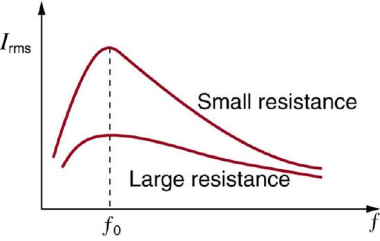
Current vs. Frequency: A graph of current versus frequency for two RLC series circuits differing only in the amount of resistance. Both have a resonance at f0, but that for the higher resistance is lower and broader. The driving AC voltage source has a fixed amplitude V0.
Power
Power delivered to an RLC series AC circuit is dissipated by the resistance in the circuit, and is given as \(\mathrm { P } _ { \mathrm { avg } } = \mathrm { I } _ { \mathrm { rms } } \mathrm { V } _ { \mathrm { rms } } \cos \phi\). Here, \(ϕ\) is called the phase angle.
learning objectives
- Calculate the power delivered to an RLC-series AC circuit given the current and the voltage
If current varies with frequency in an RLC circuit, then the power delivered to it also varies with frequency. However, the average power is not simply current times voltage, as is the case in purely resistive circuits. As seen in previous Atoms, voltage and current are out of phase in an RLC circuit. There is a phase angle ϕ between the source voltage V and the current I, given as
\(\cos \phi = \frac { \mathrm { R } } { \mathrm { Z } }\), as diagramed in.
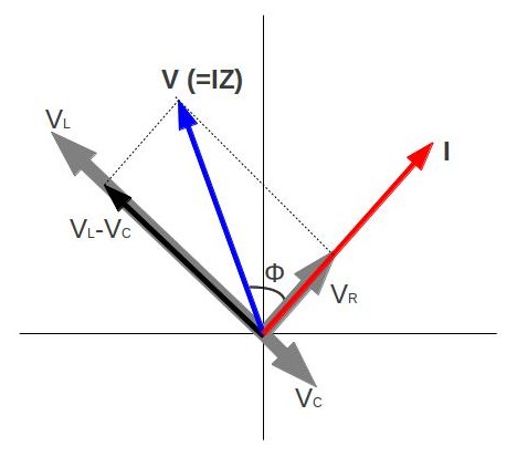
Phasor Diagram for an RLC Series Circuit: Phasor diagram for an RLC series circuit. \phi is the phase angle, equal to the phase difference between the voltage and current.
For example, at the resonant frequency (\( \nu _ { 0 } = \frac { 1 } { 2 \pi \sqrt { L C } }\)) or in a purely resistive circuit, Z=R, so that cosϕ=1. This implies that ϕ=0º and that voltage and current are in phase, as expected for resistors. At other frequencies, average power is less than at resonance, because voltage and current are out of phase and Irms is lower.
The fact that source voltage and current are out of phase affects the power delivered to the circuit. It can be shown that the average power is
\[\mathrm { P } _ { \mathrm { avg } } = \mathrm { I } _ { \mathrm { rms } } \mathrm { V } _ { \mathrm { rms } } \cos \phi\]
(an equation derived by taking a time average of power, P(t) = I(t)V(t), over a period. I(t) and V(t) are current and voltage at time t). Thus cosϕ is called the power factor, which can range from 0 to 1. Power factors near 1 are desirable when designing an efficient motor, for example. At the resonant frequency, cosϕ=1.
Power delivered to an RLC series AC circuit is dissipated by the resistance alone. The inductor and capacitor have energy input and output, but do not dissipate energy out of the circuit. Rather, they transfer energy back and forth to one another, with the resistor dissipating the exact amount that the voltage source gives the circuit. This assumes no significant electromagnetic radiation from the inductor and capacitor (such as radio waves).
The circuit is analogous to the wheel of a car driven over a corrugated road, as seen in. The regularly spaced bumps in the road are analogous to the voltage source, driving the wheel up and down. The shock absorber is analogous to the resistance damping and limiting the amplitude of the oscillation. Energy within the system goes back and forth between kinetic (analogous to maximum current, and energy stored in an inductor) and potential energy stored in the car spring (analogous to no current, and energy stored in the electric field of a capacitor). The amplitude of the wheels’ motion is a maximum if the bumps in the road are hit at the resonant frequency.
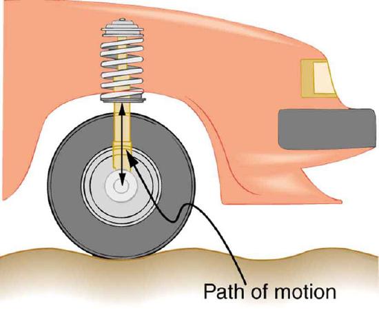
Forced Damped Motion of a Wheel on a Car Spring: The forced but damped motion of the wheel on the car spring is analogous to an RLC series AC circuit. The shock absorber damps the motion and dissipates energy, analogous to the resistance in an RLC circuit. The mass and spring determine the resonant frequency.
Key Points
- In the case of electronics, inductance is the property of a conductor by which a change in current in the conductor creates a voltage in both the conductor itself, called self-inductance, and any nearby conductors, called mutual inductance.
- From Lenz’s law, a changing electric current through a circuit that has inductance induces a proportional voltage which opposes the change in current.
- Mutual inductance is illustrated by. A change in the current I1 in one device, coil 1 in the figure, induces an emf2 in the other. We express this in equation form as \(\mathrm { emf } _ { 2 } = - \mathrm { M } \frac { \Delta \mathrm { I } _ { 1 } } { \Delta \mathrm { t } }\). M is the same for the reverse process.
- Self-inductance is the effect of Faraday’s law of induction of a device on itself. The induced emf is related to the physical geometry of the device and the rate of change of current given by \(\mathrm { emf } = - \mathrm { L } \frac { \Delta \mathrm { I } } { \Delta \mathrm{t} }\) .
- A device that exhibits significant self-inductance is called an inductor, and given the symbol in.
- The energy stored in an inductor is \(\mathrm { E } = \frac { 1 } { 2 } \mathrm { L } \mathrm { I } ^ { 2 }\). It takes time to build up stored energy in a conductor and time to deplete it.
- When a resistor and an inductor in series are connected to a voltage source, the time-dependent current is given by \(\mathrm { I } = \mathrm { I } _ { 0 } \left( 1 - \mathrm { e } ^ { \frac { - t } { \tau } } \right)\). The final current after a long time is \(\mathrm{I_0}\).
- The characteristic time constant is given by \(\tau = \frac { \mathrm { L } } { \mathrm { R } }\), where R is resistance and L is inductance. This represents the time necessary for the current in a circuit just closed to go from zero to \(\mathrm{0.632⋅I_0}\).
- When the voltage source is disconnected from the inductor, the current will decay according to \(\mathrm { I } = \mathrm { I } _ { 0 } \mathrm { e } ^ { \frac { - t } { \tau } }\). In the first time interval τ the current falls by a factor of \(\mathrm{\frac{1}{e}}\) to \(\mathrm{0.368⋅I_0}\).
- RLC circuits can be described by the (generalized) Ohm ‘s law. As for the phase, when a sinusoidal voltage is applied, the current lags the voltage by a 90º phase in a circuit with an inductor, while the current leads the voltage by 90∘ in a circuit with a capacitor.
- At large enough frequencies (\(\nu \gg \frac { 1 } { \sqrt { 2 \pi \mathrm { LC } } }\)), the circuit is almost equivalent to an AC circuit with just an inductor. Therefore, the rms current will be Vrms/XL, and the current lags the voltage by almost 90∘.
- At small enough frequencies (\(\nu \ll \frac { 1 } { \sqrt { 2 \pi \mathrm { LC } } }\)), the circuit is almost equivalent to an AC circuit with just a capacitor. Therefore, the rms current will be given as Vrms/XC, and the current leads the voltage by almost 90∘.
- With an AC voltage given by: \(\mathrm { V } = \mathrm { V } _ { 0 } \sin ( 2 \pi \nu t )\) the current in the circuit is given as: \(\mathrm { I } = \frac { \mathrm { V } _ { 0 } } { \mathrm { R } } \sin ( 2 \pi \nu t )\) This expression comes from Ohm ‘s law: \(\mathrm { V } = \mathrm { IR }\).
- Most common applications use a time-varying voltage source instead of a DC source. Examples include the commercial and residential power that serves so many of our needs.
- Power dissipated by the AC circuit with a resistor in the example is: \(\mathrm { P } = \frac { \mathrm { V } _ { 0 } ^ { 2 } } { \mathrm { R } } \cdot \sin ( 2 \pi \nu t )\) Therefore, average AC power is: \(\frac { \mathrm { V } _ { 0 } ^ { 2 } } { 2 \mathrm { R } }\).
- When a capacitor is connected to an alternating voltage, the maximum voltage is proportional to the maximum current, but the maximum voltage does not occur at the same time as the maximum current.
- If the AC supply is connected to a resistor, then the current and voltage will be proportional to each other. This means that the current and voltage will “peak” at the same time.
- The rms current in the circuit containing only a capacitor C is given by another version of Ohm ‘s law to be \(\mathrm { I } _ { \mathrm { rms } } = \frac { \mathrm { V } _ { \mathrm { rms } } } { \mathrm { X } _ { \mathrm { C } } }\), where \(\mathrm{X_c}\) is the capacitive reactance.
- With an inductor in an AC circuit, the voltage leads the current by one-fourth of a cycle, or by a 90º phase angle.
- The rms current Irms through an inductor L is given by a version of Ohm ‘s law: \(\mathrm { I } _ { \mathrm { rms } } = \frac { \mathrm { V } _ { \mathrm { rms } } } { \mathrm { X } _ { \mathrm { L } } }\). XL is called the inductive reactance, given as \(\mathrm { X } _ { \mathrm { L } } = 2 \pi \nu \mathrm { L }\).
- Phasors are vectors rotating in counter-clockwise direction. A phasor for an inductor shows that the voltage lead the current by a 90º phase.
- Resonance condition of an RLC series circuit can be obtained by equating XL and XC, so that the two opposing phasors cancel each other.
- At resonance, the effects of the inductor and capacitor cancel, so that Z=R, and Irms is a maximum.
- Higher- resistance circuits do not resonate as strongly compared to lower-resistance circuits, nor would they be as selective in, for example, a radio receiver.
- Phase angle ϕ is the phase difference between the source voltage V and the current I. See the phasor diagram in.
- At the resonant frequency or in a purely resistive circuit Z=R, so that cosϕ=1. This implies that ϕ=0º and that voltage and current are in phase.
- Average power dissipated in an RLC circuit can be calculated by taking a time average of power, P(t) = I(t)V(t), over a period.
Key Terms
- mutual inductance: The ratio of the voltage in a circuit to the change in current in a neighboring circuit.
- self-inductance: The ratio of the voltage to the change in current in the same circuit.
- inductor: A passive device that introduces inductance into an electrical circuit.
- characteristic time constant: Denoted by \(\tau\), in RL circuits it is given by \(\tau=\frac{L}{R}\) where R is resistance and L is inductance. When a switch is closed, it is the time it takes for the current to decay by a factor of 1/e.
- inductor: A device or circuit component that exhibits significant self-inductance; a device which stores energy in a magnetic field.
- Lenz’s law: A law of electromagnetic induction that states that an electromotive force, induced in a conductor, is always in such a direction that the current produced would oppose the change that caused it; this law is a form of the law of conservation of energy.
- resonance: The increase in the amplitude of an oscillation of a system under the influence of a periodic force whose frequency is close to that of the system’s natural frequency.
- rms: Root mean square: a statistical measure of the magnitude of a varying quantity.
- phasor: A representation of a complex number in terms of a complex exponential.
- reactance: The opposition to the change in flow of current in an alternating current circuit, due to inductance and capacitance; the imaginary part of the impedance.
- impedance: A measure of the opposition to the flow of an alternating current in a circuit; the aggregation of its resistance, inductive and capacitive reactance. Represented by the symbol Z.
- Ohm’s law: Ohm’s observation is that the direct current flowing in an electrical circuit consisting only of resistances is directly proportional to the voltage applied.
LICENSES AND ATTRIBUTIONS
CC LICENSED CONTENT, SHARED PREVIOUSLY
- Curation and Revision. Provided by: Boundless.com. License: CC BY-SA: Attribution-ShareAlike
CC LICENSED CONTENT, SPECIFIC ATTRIBUTION
- OpenStax College, College Physics. September 18, 2013. Provided by: OpenStax CNX. Located at: http://cnx.org/content/m42420/latest/?collection=col11406/1.7. License: CC BY: Attribution
- Inductance. Provided by: Wikipedia. Located at: en.Wikipedia.org/wiki/Inductance. License: CC BY-SA: Attribution-ShareAlike
- Boundless. Provided by: Boundless Learning. Located at: www.boundless.com//physics/definition/self-inductance--2. License: CC BY-SA: Attribution-ShareAlike
- inductor. Provided by: Wiktionary. Located at: en.wiktionary.org/wiki/inductor. License: CC BY-SA: Attribution-ShareAlike
- mutual inductance. Provided by: Wiktionary. Located at: en.wiktionary.org/wiki/mutual_inductance. License: CC BY-SA: Attribution-ShareAlike
- OpenStax College, College Physics. January 8, 2013. Provided by: OpenStax CNX. Located at: http://cnx.org/content/m42420/latest/?collection=col11406/1.7. License: CC BY: Attribution
- OpenStax College, College Physics. January 8, 2013. Provided by: OpenStax CNX. Located at: http://cnx.org/content/m42420/latest/?collection=col11406/1.7. License: CC BY: Attribution
- OpenStax College, College Physics. January 8, 2013. Provided by: OpenStax CNX. Located at: http://cnx.org/content/m42420/latest/?collection=col11406/1.7. License: CC BY: Attribution
- Rl circuit. Provided by: Wikipedia. Located at: en.Wikipedia.org/wiki/Rl_circuit. License: CC BY-SA: Attribution-ShareAlike
- OpenStax College, College Physics. September 17, 2013. Provided by: OpenStax CNX. Located at: http://cnx.org/content/m42425/latest/?collection=col11406/1.7. License: CC BY: Attribution
- OpenStax College, College Physics. September 17, 2013. Provided by: OpenStax CNX. Located at: http://cnx.org/content/m42420/latest/?collection=col11406/1.7. License: CC BY: Attribution
- inductor. Provided by: Wiktionary. Located at: en.wiktionary.org/wiki/inductor. License: CC BY-SA: Attribution-ShareAlike
- Boundless. Provided by: Boundless Learning. Located at: www.boundless.com//physics/definition/characteristic-time-constant. License: CC BY-SA: Attribution-ShareAlike
- OpenStax College, College Physics. January 8, 2013. Provided by: OpenStax CNX. Located at: http://cnx.org/content/m42420/latest/?collection=col11406/1.7. License: CC BY: Attribution
- OpenStax College, College Physics. January 8, 2013. Provided by: OpenStax CNX. Located at: http://cnx.org/content/m42420/latest/?collection=col11406/1.7. License: CC BY: Attribution
- OpenStax College, College Physics. January 8, 2013. Provided by: OpenStax CNX. Located at: http://cnx.org/content/m42420/latest/?collection=col11406/1.7. License: CC BY: Attribution
- OpenStax College, College Physics. January 25, 2013. Provided by: OpenStax CNX. Located at: http://cnx.org/content/m42425/latest/?collection=col11406/1.7. License: CC BY: Attribution
- Lenz's law. Provided by: Wiktionary. Located at: en.wiktionary.org/wiki/Lenz's_law. License: CC BY-SA: Attribution-ShareAlike
- OpenStax College, RLC Series AC Circuits. September 17, 2013. Provided by: OpenStax CNX. Located at: http://cnx.org/content/m42431/latest/. License: CC BY: Attribution
- resonance. Provided by: Wiktionary. Located at: en.wiktionary.org/wiki/resonance. License: CC BY-SA: Attribution-ShareAlike
- rms. Provided by: Wikipedia. Located at: en.Wikipedia.org/wiki/rms. License: CC BY-SA: Attribution-ShareAlike
- OpenStax College, College Physics. January 8, 2013. Provided by: OpenStax CNX. Located at: http://cnx.org/content/m42420/latest/?collection=col11406/1.7. License: CC BY: Attribution
- OpenStax College, College Physics. January 8, 2013. Provided by: OpenStax CNX. Located at: http://cnx.org/content/m42420/latest/?collection=col11406/1.7. License: CC BY: Attribution
- OpenStax College, College Physics. January 8, 2013. Provided by: OpenStax CNX. Located at: http://cnx.org/content/m42420/latest/?collection=col11406/1.7. License: CC BY: Attribution
- OpenStax College, College Physics. January 25, 2013. Provided by: OpenStax CNX. Located at: http://cnx.org/content/m42425/latest/?collection=col11406/1.7. License: CC BY: Attribution
- RLC circuit. Provided by: Wikipedia. Located at: en.Wikipedia.org/wiki/RLC_circuit%23Laplace_domain. License: CC BY: Attribution
- OpenStax College, College Physics. September 17, 2013. Provided by: OpenStax CNX. Located at: http://cnx.org/content/m42348/latest/?collection=col11406/1.7. License: CC BY: Attribution
- Ohm's law. Provided by: Wiktionary. Located at: en.wiktionary.org/wiki/Ohm's_law. License: CC BY-SA: Attribution-ShareAlike
- OpenStax College, College Physics. January 8, 2013. Provided by: OpenStax CNX. Located at: http://cnx.org/content/m42420/latest/?collection=col11406/1.7. License: CC BY: Attribution
- OpenStax College, College Physics. January 8, 2013. Provided by: OpenStax CNX. Located at: http://cnx.org/content/m42420/latest/?collection=col11406/1.7. License: CC BY: Attribution
- OpenStax College, College Physics. January 8, 2013. Provided by: OpenStax CNX. Located at: http://cnx.org/content/m42420/latest/?collection=col11406/1.7. License: CC BY: Attribution
- OpenStax College, College Physics. January 25, 2013. Provided by: OpenStax CNX. Located at: http://cnx.org/content/m42425/latest/?collection=col11406/1.7. License: CC BY: Attribution
- RLC circuit. Provided by: Wikipedia. Located at: en.Wikipedia.org/wiki/RLC_circuit%23Laplace_domain. License: CC BY: Attribution
- OpenStax College, College Physics. January 16, 2015. Provided by: OpenStax CNX. Located at: http://cnx.org/content/m42348/latest/?collection=col11406/1.7. License: CC BY: Attribution
- OpenStax College, College Physics. September 17, 2013. Provided by: OpenStax CNX. Located at: http://cnx.org/content/m42427/latest/?collection=col11406/1.7. License: CC BY: Attribution
- Free High School Science Texts Project, Electronics: Capacitive and Inductive Circuits. September 17, 2013. Provided by: OpenStax CNX. Located at: http://cnx.org/content/m39523/latest/. License: CC BY: Attribution
- Phasor. Provided by: Wikipedia. Located at: en.Wikipedia.org/wiki/Phasor. License: CC BY-SA: Attribution-ShareAlike
- rms. Provided by: Wikipedia. Located at: en.Wikipedia.org/wiki/rms. License: CC BY-SA: Attribution-ShareAlike
- OpenStax College, College Physics. January 8, 2013. Provided by: OpenStax CNX. Located at: http://cnx.org/content/m42420/latest/?collection=col11406/1.7. License: CC BY: Attribution
- OpenStax College, College Physics. January 8, 2013. Provided by: OpenStax CNX. Located at: http://cnx.org/content/m42420/latest/?collection=col11406/1.7. License: CC BY: Attribution
- OpenStax College, College Physics. January 8, 2013. Provided by: OpenStax CNX. Located at: http://cnx.org/content/m42420/latest/?collection=col11406/1.7. License: CC BY: Attribution
- OpenStax College, College Physics. January 25, 2013. Provided by: OpenStax CNX. Located at: http://cnx.org/content/m42425/latest/?collection=col11406/1.7. License: CC BY: Attribution
- RLC circuit. Provided by: Wikipedia. Located at: en.Wikipedia.org/wiki/RLC_circuit%23Laplace_domain. License: CC BY: Attribution
- OpenStax College, College Physics. January 16, 2015. Provided by: OpenStax CNX. Located at: http://cnx.org/content/m42348/latest/?collection=col11406/1.7. License: CC BY: Attribution
- Phasor. Provided by: Wikipedia. Located at: en.Wikipedia.org/wiki/Phasor. License: CC BY: Attribution
- Boundless. Provided by: Amazon Web Services. Located at: s3.amazonaws.com/figures.boundless.com/510acb88e4b0f11e4bcb056e/1.jpg. License: CC BY: Attribution
- Free High School Science Texts Project, Electronics: Capacitive and Inductive Circuits. January 31, 2013. Provided by: OpenStax CNX. Located at: http://cnx.org/content/m39523/latest/. License: CC BY: Attribution
- Capacitors in AC Circuits with Phasors. Located at: http://www.youtube.com/watch?v=P9xSEhPENqM. License: Public Domain: No Known Copyright. License Terms: Standard YouTube license
- OpenStax College, College Physics. September 17, 2013. Provided by: OpenStax CNX. Located at: http://cnx.org/content/m42427/latest/?collection=col11406/1.7. License: CC BY: Attribution
- rms. Provided by: Wikipedia. Located at: en.Wikipedia.org/wiki/rms. License: CC BY-SA: Attribution-ShareAlike
- phasor. Provided by: Wiktionary. Located at: en.wiktionary.org/wiki/phasor. License: CC BY-SA: Attribution-ShareAlike
- Lenz's law. Provided by: Wiktionary. Located at: en.wiktionary.org/wiki/Lenz's_law. License: CC BY-SA: Attribution-ShareAlike
- OpenStax College, College Physics. January 8, 2013. Provided by: OpenStax CNX. Located at: http://cnx.org/content/m42420/latest/?collection=col11406/1.7. License: CC BY: Attribution
- OpenStax College, College Physics. January 8, 2013. Provided by: OpenStax CNX. Located at: http://cnx.org/content/m42420/latest/?collection=col11406/1.7. License: CC BY: Attribution
- OpenStax College, College Physics. January 8, 2013. Provided by: OpenStax CNX. Located at: http://cnx.org/content/m42420/latest/?collection=col11406/1.7. License: CC BY: Attribution
- OpenStax College, College Physics. January 25, 2013. Provided by: OpenStax CNX. Located at: http://cnx.org/content/m42425/latest/?collection=col11406/1.7. License: CC BY: Attribution
- RLC circuit. Provided by: Wikipedia. Located at: en.Wikipedia.org/wiki/RLC_circuit%23Laplace_domain. License: CC BY: Attribution
- OpenStax College, College Physics. January 16, 2015. Provided by: OpenStax CNX. Located at: http://cnx.org/content/m42348/latest/?collection=col11406/1.7. License: CC BY: Attribution
- Phasor. Provided by: Wikipedia. Located at: en.Wikipedia.org/wiki/Phasor. License: CC BY: Attribution
- Boundless. Provided by: Amazon Web Services. Located at: s3.amazonaws.com/figures.boundless.com/510acb88e4b0f11e4bcb056e/1.jpg. License: CC BY: Attribution
- Free High School Science Texts Project, Electronics: Capacitive and Inductive Circuits. January 31, 2013. Provided by: OpenStax CNX. Located at: http://cnx.org/content/m39523/latest/. License: CC BY: Attribution
- Capacitors in AC Circuits with Phasors. Located at: http://www.youtube.com/watch?v=P9xSEhPENqM. License: Public Domain: No Known Copyright. License Terms: Standard YouTube license
- Phasors for Inductors in AC Circuits. Located at: http://www.youtube.com/watch?v=8-veJf_JX3g. License: Public Domain: No Known Copyright. License Terms: Standard YouTube license
- Boundless. Provided by: Amazon Web Services. Located at: s3.amazonaws.com/figures.boundless.com/510ad330e4b0c14bf464a066/2.jpg. License: CC BY: Attribution
- OpenStax College, College Physics. January 31, 2013. Provided by: OpenStax CNX. Located at: http://cnx.org/content/m42427/latest/?collection=col11406/1.7. License: CC BY: Attribution
- Resonance. Provided by: Wikipedia. Located at: en.Wikipedia.org/wiki/Resonance. License: CC BY-SA: Attribution-ShareAlike
- OpenStax College, RLC Series AC Circuits. September 17, 2013. Provided by: OpenStax CNX. Located at: http://cnx.org/content/m42431/latest/. License: CC BY: Attribution
- rms. Provided by: Wikipedia. Located at: en.Wikipedia.org/wiki/rms. License: CC BY-SA: Attribution-ShareAlike
- reactance. Provided by: Wiktionary. Located at: en.wiktionary.org/wiki/reactance. License: CC BY-SA: Attribution-ShareAlike
- impedance. Provided by: Wiktionary. Located at: en.wiktionary.org/wiki/impedance. License: CC BY-SA: Attribution-ShareAlike
- OpenStax College, College Physics. January 8, 2013. Provided by: OpenStax CNX. Located at: http://cnx.org/content/m42420/latest/?collection=col11406/1.7. License: CC BY: Attribution
- OpenStax College, College Physics. January 8, 2013. Provided by: OpenStax CNX. Located at: http://cnx.org/content/m42420/latest/?collection=col11406/1.7. License: CC BY: Attribution
- OpenStax College, College Physics. January 8, 2013. Provided by: OpenStax CNX. Located at: http://cnx.org/content/m42420/latest/?collection=col11406/1.7. License: CC BY: Attribution
- OpenStax College, College Physics. January 25, 2013. Provided by: OpenStax CNX. Located at: http://cnx.org/content/m42425/latest/?collection=col11406/1.7. License: CC BY: Attribution
- RLC circuit. Provided by: Wikipedia. Located at: en.Wikipedia.org/wiki/RLC_circuit%23Laplace_domain. License: CC BY: Attribution
- OpenStax College, College Physics. January 16, 2015. Provided by: OpenStax CNX. Located at: http://cnx.org/content/m42348/latest/?collection=col11406/1.7. License: CC BY: Attribution
- Phasor. Provided by: Wikipedia. Located at: en.Wikipedia.org/wiki/Phasor. License: CC BY: Attribution
- Boundless. Provided by: Amazon Web Services. Located at: s3.amazonaws.com/figures.boundless.com/510acb88e4b0f11e4bcb056e/1.jpg. License: CC BY: Attribution
- Free High School Science Texts Project, Electronics: Capacitive and Inductive Circuits. January 31, 2013. Provided by: OpenStax CNX. Located at: http://cnx.org/content/m39523/latest/. License: CC BY: Attribution
- Capacitors in AC Circuits with Phasors. Located at: http://www.youtube.com/watch?v=P9xSEhPENqM. License: Public Domain: No Known Copyright. License Terms: Standard YouTube license
- Phasors for Inductors in AC Circuits. Located at: http://www.youtube.com/watch?v=8-veJf_JX3g. License: Public Domain: No Known Copyright. License Terms: Standard YouTube license
- Boundless. Provided by: Amazon Web Services. Located at: s3.amazonaws.com/figures.boundless.com/510ad330e4b0c14bf464a066/2.jpg. License: CC BY: Attribution
- OpenStax College, College Physics. January 31, 2013. Provided by: OpenStax CNX. Located at: http://cnx.org/content/m42427/latest/?collection=col11406/1.7. License: CC BY: Attribution
- OpenStax College, RLC Series AC Circuits. January 31, 2013. Provided by: OpenStax CNX. Located at: http://cnx.org/content/m42431/latest/. License: CC BY: Attribution
- OpenStax College, RLC Series AC Circuits. January 31, 2013. Provided by: OpenStax CNX. Located at: http://cnx.org/content/m42431/latest/. License: CC BY: Attribution
- OpenStax College, RLC Series AC Circuits. September 17, 2013. Provided by: OpenStax CNX. Located at: http://cnx.org/content/m42431/latest/. License: CC BY: Attribution
- rms. Provided by: Wikipedia. Located at: en.Wikipedia.org/wiki/rms. License: CC BY-SA: Attribution-ShareAlike
- OpenStax College, College Physics. January 8, 2013. Provided by: OpenStax CNX. Located at: http://cnx.org/content/m42420/latest/?collection=col11406/1.7. License: CC BY: Attribution
- OpenStax College, College Physics. January 8, 2013. Provided by: OpenStax CNX. Located at: http://cnx.org/content/m42420/latest/?collection=col11406/1.7. License: CC BY: Attribution
- OpenStax College, College Physics. January 8, 2013. Provided by: OpenStax CNX. Located at: http://cnx.org/content/m42420/latest/?collection=col11406/1.7. License: CC BY: Attribution
- OpenStax College, College Physics. January 25, 2013. Provided by: OpenStax CNX. Located at: http://cnx.org/content/m42425/latest/?collection=col11406/1.7. License: CC BY: Attribution
- RLC circuit. Provided by: Wikipedia. Located at: en.Wikipedia.org/wiki/RLC_circuit%23Laplace_domain. License: CC BY: Attribution
- OpenStax College, College Physics. January 16, 2015. Provided by: OpenStax CNX. Located at: http://cnx.org/content/m42348/latest/?collection=col11406/1.7. License: CC BY: Attribution
- Phasor. Provided by: Wikipedia. Located at: en.Wikipedia.org/wiki/Phasor. License: CC BY: Attribution
- Boundless. Provided by: Amazon Web Services. Located at: s3.amazonaws.com/figures.boundless.com/510acb88e4b0f11e4bcb056e/1.jpg. License: CC BY: Attribution
- Free High School Science Texts Project, Electronics: Capacitive and Inductive Circuits. January 31, 2013. Provided by: OpenStax CNX. Located at: http://cnx.org/content/m39523/latest/. License: CC BY: Attribution
- Capacitors in AC Circuits with Phasors. Located at: http://www.youtube.com/watch?v=P9xSEhPENqM. License: Public Domain: No Known Copyright. License Terms: Standard YouTube license
- Phasors for Inductors in AC Circuits. Located at: http://www.youtube.com/watch?v=8-veJf_JX3g. License: Public Domain: No Known Copyright. License Terms: Standard YouTube license
- Boundless. Provided by: Amazon Web Services. Located at: s3.amazonaws.com/figures.boundless.com/510ad330e4b0c14bf464a066/2.jpg. License: CC BY: Attribution
- OpenStax College, College Physics. January 31, 2013. Provided by: OpenStax CNX. Located at: http://cnx.org/content/m42427/latest/?collection=col11406/1.7. License: CC BY: Attribution
- OpenStax College, RLC Series AC Circuits. January 31, 2013. Provided by: OpenStax CNX. Located at: http://cnx.org/content/m42431/latest/. License: CC BY: Attribution
- OpenStax College, RLC Series AC Circuits. January 31, 2013. Provided by: OpenStax CNX. Located at: http://cnx.org/content/m42431/latest/. License: CC BY: Attribution
- OpenStax College, RLC Series AC Circuits. February 1, 2013. Provided by: OpenStax CNX. Located at: http://cnx.org/content/m42431/latest/. License: CC BY: Attribution
- Boundless. Provided by: Amazon Web Services. Located at: s3.amazonaws.com/figures.boundless.com/510b06ffe4b0c14bf464a30e/4.jpg. License: CC BY: Attribution