10.9: Direct-Current Circuits (Exercise)
( \newcommand{\kernel}{\mathrm{null}\,}\)
Conceptual Questions
10.2 Electromotive Force
1. What effect will the internal resistance of a rechargeable battery have on the energy being used to recharge the battery?
2. A battery with an internal resistance of r and an emf of 10.00 V is connected to a load resistor R=r. As the battery ages, the internal resistance triples. How much is the current through the load resistor reduced?
3. Show that the power dissipated by the load resistor is maximum when the resistance of the load resistor is equal to the internal resistance of the battery.
10.3 Resistors in Series and Parallel
4. A voltage occurs across an open switch. What is the power dissipated by the open switch?
5. The severity of a shock depends on the magnitude of the current through your body. Would you prefer to be in series or in parallel with a resistance, such as the heating element of a toaster, if you were shocked by it? Explain.
6. Suppose you are doing a physics lab that asks you to put a resistor into a circuit, but all the resistors supplied have a larger resistance than the requested value. How would you connect the available resistances to attempt to get the smaller value asked for?
7. Some light bulbs have three power settings (not including zero), obtained from multiple filaments that are individually switched and wired in parallel. What is the minimum number of filaments needed for three power settings?
10.4 Kirchhoff's Rules
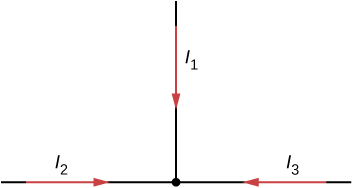
8. Can all of the currents going into the junction shown below be positive? Explain.
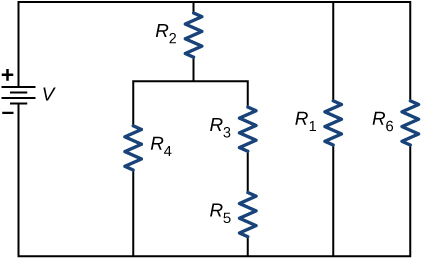
9. Consider the circuit shown below. Does the analysis of the circuit require Kirchhoff’s method, or can it be redrawn to simplify the circuit? If it is a circuit of series and parallel connections, what is the equivalent resistance?
10. Do batteries in a circuit always supply power to a circuit, or can they absorb power in a circuit? Give an example.
11. What are the advantages and disadvantages of connecting batteries in series? In parallel?
12. Semi-tractor trucks use four large 12-V batteries. The starter system requires 24 V, while normal operation of the truck’s other electrical components utilizes 12 V. How could the four batteries be connected to produce 24 V? To produce 12 V? Why is 24 V better than 12 V for starting the truck’s engine (a very heavy load)?
10.5 Electrical Measuring Instruments
13. What would happen if you placed a voltmeter in series with a component to be tested?
14. What is the basic operation of an ohmmeter as it measures a resistor?
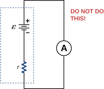
15. Why should you not connect an ammeter directly across a voltage source as shown below?
10.6 RC Circuits
16. A battery, switch, capacitor, and lamp are connected in series. Describe what happens to the lamp when the switch is closed.
17. When making an ECG measurement, it is important to measure voltage variations over small time intervals. The time is limited by the RC constant of the circuit—it is not possible to measure time variations shorter than RC. How would you manipulate R and C in the circuit to allow the necessary measurements?
10.6 Household Wiring and Electrical Safety
18. Why isn’t a short circuit necessarily a shock hazard?
19. We are often advised to not flick electric switches with wet hands, dry your hand first. We are also advised to never throw water on an electric fire. Why?
Problems
10.2 Electromotive Force
20. A car battery with a 12-V emf and an internal resistance of 0.050Ω is being charged with a current of 60 A. Note that in this process, the battery is being charged.
(a) What is the potential difference across its terminals?
(b) At what rate is thermal energy being dissipated in the battery?
(c) At what rate is electric energy being converted into chemical energy?
21. The label on a battery-powered radio recommends the use of rechargeable nickel-cadmium cells (nicads), although they have a 1.25-V emf, whereas alkaline cells have a 1.58-V emf. The radio has a 3.20Ω resistance.
(a) Draw a circuit diagram of the radio and its batteries. Now, calculate the power delivered to the radio
(b) when using nicad cells, each having an internal resistance of 0.0400Ω, and
(c) when using alkaline cells, each having an internal resistance of 0.200Ω.
(d) Does this difference seem significant, considering that the radio’s effective resistance is lowered when its volume is turned up?
22. An automobile starter motor has an equivalent resistance of 0.0500Ω and is supplied by a 12.0-V battery with a 0.0100-Ω internal resistance.
(a) What is the current to the motor?
(b) What voltage is applied to it?
(c) What power is supplied to the motor?
(d) Repeat these calculations for when the battery connections are corroded and add 0.0900Ω to the circuit. (Significant problems are caused by even small amounts of unwanted resistance in low-voltage, high-current applications.)
23. (a) What is the internal resistance of a voltage source if its terminal potential drops by 2.00 V when the current supplied increases by 5.00 A?
(b) Can the emf of the voltage source be found with the information supplied?
24. A person with body resistance between his hands of 10.0kΩ accidentally grasps the terminals of a 20.0-kV power supply. (Do NOT do this!)
(a) Draw a circuit diagram to represent the situation.
(b) If the internal resistance of the power supply is 2000Ω, what is the current through his body?
(c) What is the power dissipated in his body?
(d) If the power supply is to be made safe by increasing its internal resistance, what should the internal resistance be for the maximum current in this situation to be 1.00 mA or less?
(e) Will this modification compromise the effectiveness of the power supply for driving low-resistance devices? Explain your reasoning.
25. A 12.0-V emf automobile battery has a terminal voltage of 16.0 V when being charged by a current of 10.0 A.
(a) What is the battery’s internal resistance?
(b) What power is dissipated inside the battery?
(c) At what rate (in °C/min) will its temperature increase if its mass is 20.0 kg and it has a specific heat of 0.300kcal/kg⋅°C, assuming no heat escapes?
10.3 Resistors in Series and Parallel
26. (a) What is the resistance of a 1.00×10²−Ω, a 2.50−kΩ, and a 4.00−kΩ resistor connected in series?
(b) In parallel?
27. What are the largest and smallest resistances you can obtain by connecting a 36.0-Ω, a 50.0-Ω, and a 700-Ω resistor together?
28. An 1800-W toaster, a 1400-W speaker, and a 75-W lamp are plugged into the same outlet in a 15-A fuse and 120-V circuit. (The three devices are in parallel when plugged into the same socket.)
(a) What current is drawn by each device?
(b) Will this combination blow the 15-A fuse?
29. Your car’s 30.0-W headlight and 2.40-kW starter are ordinarily connected in parallel in a 12.0-V system. What power would one headlight and the starter consume if connected in series to a 12.0-V battery? (Neglect any other resistance in the circuit and any change in resistance in the two devices.)
30. (a) Given a 48.0-V battery and 24.0-Ω and 96.0-Ω9 resistors, find the current and power for each when connected in series.
(b) Repeat when the resistances are in parallel.
31. Referring to the example combining series and parallel circuits and Figure 10.16, calculate I3 in the following two different ways:
(a) from the known values of I and I2;
(b) using Ohm’s law for R3. In both parts, explicitly show how you follow the steps in the Figure 10.17.
32. Referring to Figure 10.16,
(a) Calculate P3 and note how it compares with P3 found in the first two example problems in this module.
(b) Find the total power supplied by the source and compare it with the sum of the powers dissipated by the resistors.
33. Refer to Figure 10.17 and the discussion of lights dimming when a heavy appliance comes on.
(a) Given the voltage source is 120 V, the wire resistance is 0.800Ω, and the bulb is nominally 75.0 W, what power will the bulb dissipate if a total of 15.0 A passes through the wires when the motor comes on? Assume negligible change in bulb resistance.
(b) What power is consumed by the motor?
34. Show that if two resistors R1 and R2 are combined and one is much greater than the other (R1≫R2),
(a) their series resistance is very nearly equal to the greater resistance R1 and
(b) their parallel resistance is very nearly equal to the smaller resistance R2.
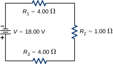
35. Consider the circuit shown below. The terminal voltage of the battery is V=18.00V.
(a) Find the equivalent resistance of the circuit.
(b) Find the current through each resistor.
(c) Find the potential drop across each resistor.
(d) Find the power dissipated by each resistor. (e) Find the power supplied by the battery.
10.4 Kirchhoff's Rules
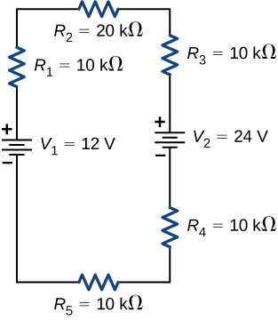
36. Consider the circuit shown below.
(a) Find the voltage across each resistor.
(b)What is the power supplied to the circuit and the power dissipated or consumed by the circuit?
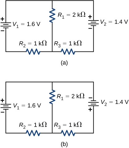
37. Consider the circuits shown below.
(a) What is the current through each resistor in part (a)?
(b) What is the current through each resistor in part (b)?
(c) What is the power dissipated or consumed by each circuit?
(d) What is the power supplied to each circuit?
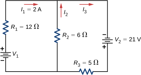
38. Consider the circuit shown below. Find V1,I2, and I3.
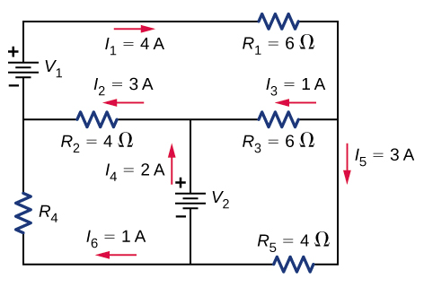
39. Consider the circuit shown below. Find V1,V2, and R4.
40. Consider the circuit shown below. Find I1,I2, and I3.
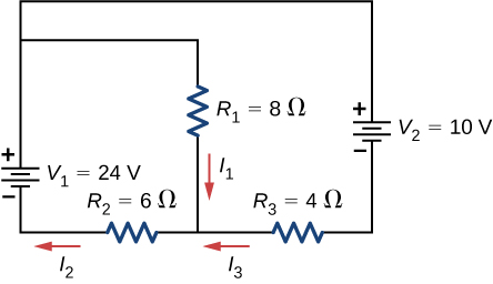
41. Consider the circuit shown below.
(a) Find I1,I2,I3,I4, and I5.
(b) Find the power supplied by the voltage sources.
(c) Find the power dissipated by the resistors
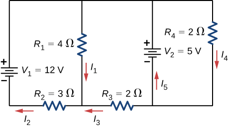
42. Consider the circuit shown below. Write the three loop equations for the loops shown.
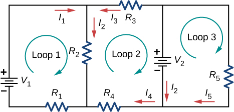
43. Consider the circuit shown below. Write equations for the three currents in terms of R and V.
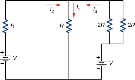
44. Consider the circuit shown in the preceding problem. Write equations for the power supplied by the voltage sources and the power dissipated by the resistors in terms of R and V.
45. A child’s electronic toy is supplied by three 1.58-V alkaline cells having internal resistances of 0.0200Ω in series with a 1.53-V carbon-zinc dry cell having a 0.100-Ω internal resistance. The load resistance is 10.0Ω.
(a) Draw a circuit diagram of the toy and its batteries.
(b) What current flows?
(c) How much power is supplied to the load?
(d) What is the internal resistance of the dry cell if it goes bad, resulting in only 0.500 W being supplied to the load?
46. Apply the junction rule to Junction b shown below. Is any new information gained by applying the junction rule at e?
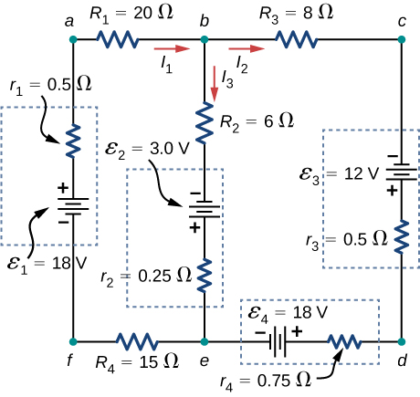
47. Apply the loop rule to Loop afedcba in the preceding problem.
10.5 Electrical Measuring Instruments
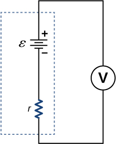
48. Suppose you measure the terminal voltage of a 1.585-V alkaline cell having an internal resistance of 0.100Ω by placing a 1.00-kΩ voltmeter across its terminals (see below).
(a) What current flows?
(b) Find the terminal voltage.
(c) To see how close the measured terminal voltage is to the emf, calculate their ratio.
10.6 RC Circuits
49. The timing device in an automobile’s intermittent wiper system is based on an RC time constant and utilizes a 0.500-μF capacitor and a variable resistor. Over what range must R be made to vary to achieve time constants from 2.00 to 15.0 s?
50. A heart pacemaker fires 72 times a minute, each time a 25.0-nF capacitor is charged (by a battery in series with a resistor) to 0.632 of its full voltage. What is the value of the resistance?
51. The duration of a photographic flash is related to an RC time constant, which is 0.100μs for a certain camera.
(a) If the resistance of the flash lamp is 0.0400Ω during discharge, what is the size of the capacitor supplying its energy?
(b) What is the time constant for charging the capacitor, if the charging resistance is 800kΩ?
52. A 2.00- and a 7.50-μF capacitor can be connected in series or parallel, as can a 25.0- and a 100-kΩ resistor. Calculate the four RC time constants possible from connecting the resulting capacitance and resistance in series.
53. A 500-Ω resistor, an uncharged 1.50-μF capacitor, and a 6.16-V emf are connected in series.
(a) What is the initial current?
(b) What is the RC time constant?
(c) What is the current after one time constant? (d) What is the voltage on the capacitor after one time constant?
54. A heart defibrillator being used on a patient has an RC time constant of 10.0 ms due to the resistance of the patient and the capacitance of the defibrillator.
(a) If the defibrillator has a capacitance of 8.00μF, what is the resistance of the path through the patient? (You may neglect the capacitance of the patient and the resistance of the defibrillator.)
(b) If the initial voltage is 12.0 kV, how long does it take to decline to 6.00×10²V?
55. An ECG monitor must have an RC time constant less than 1.00×10²μs to be able to measure variations in voltage over small time intervals.
(a) If the resistance of the circuit (due mostly to that of the patient’s chest) is 1.00kΩ, what is the maximum capacitance of the circuit?
(b) Would it be difficult in practice to limit the capacitance to less than the value found in (a)?
56. Using the exact exponential treatment, determine how much time is required to charge an initially uncharged 100-pF capacitor through a 75.0-MΩ resistor to 90.0% of its final voltage.
57. If you wish to take a picture of a bullet traveling at 500 m/s, then a very brief flash of light produced by an RC discharge through a flash tube can limit blurring. Assuming 1.00 mm of motion during one RC constant is acceptable, and given that the flash is driven by a 600-μF capacitor, what is the resistance in the flash tube?
10.7 Household Wiring and Electrical Safety
58. (a) How much power is dissipated in a short circuit of 240-V ac through a resistance of 0.250Ω? (b) What current flows?
59. What voltage is involved in a 1.44-kW short circuit through a 0.100-Ω resistance?
60. Find the current through a person and identify the likely effect on her if she touches a 120-V ac source:
(a) if she is standing on a rubber mat and offers a total resistance of 300kΩ;
(b) if she is standing barefoot on wet grass and has a resistance of only 4000kΩ.
61. While taking a bath, a person touches the metal case of a radio. The path through the person to the drainpipe and ground has a resistance of 4000Ω. What is the smallest voltage on the case of the radio that could cause ventricular fibrillation?
62. A man foolishly tries to fish a burning piece of bread from a toaster with a metal butter knife and comes into contact with 120-V ac. He does not even feel it since, luckily, he is wearing rubber-soled shoes. What is the minimum resistance of the path the current follows through the person?
63. (a) During surgery, a current as small as 20.0μA applied directly to the heart may cause ventricular fibrillation. If the resistance of the exposed heart is 300Ω, what is the smallest voltage that poses this danger?
(b) Does your answer imply that special electrical safety precautions are needed?
64. (a) What is the resistance of a 220-V ac short circuit that generates a peak power of 96.8 kW?
(b) What would the average power be if the voltage were 120 V ac?
65. A heart defibrillator passes 10.0 A through a patient’s torso for 5.00 ms in an attempt to restore normal beating.
(a) How much charge passed?
(b) What voltage was applied if 500 J of energy was dissipated?
(c) What was the path’s resistance? (d) Find the temperature increase caused in the 8.00 kg of affected tissue.
66. A short circuit in a 120-V appliance cord has a 0.500-Ω resistance. Calculate the temperature rise of the 2.00 g of surrounding materials, assuming their specific heat capacity is 0.200cal/g⋅°C and that it takes 0.0500 s for a circuit breaker to interrupt the current. Is this likely to be damaging?
Additional Problems
67. A circuit contains a D cell battery, a switch, a 20-Ω resistor, and four 20-mF capacitors connected in series.
(a) What is the equivalent capacitance of the circuit?
(b) What is the RC time constant?
(c) How long before the current decreases to 50% of the initial value once the switch is closed?
68. A circuit contains a D-cell battery, a switch, a 20-Ω resistor, and three 20-mF capacitors. The capacitors are connected in parallel, and the parallel connection of capacitors are connected in series with the switch, the resistor and the battery.
(a) What is the equivalent capacitance of the circuit?
(b) What is the RC time constant?
(c) How long before the current decreases to 50% of the initial value once the switch is closed?
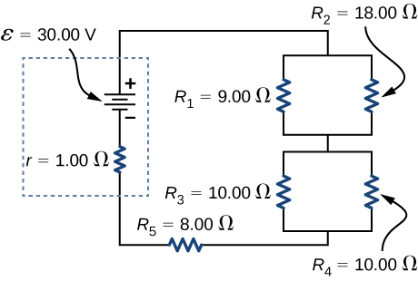
69. Consider the circuit below. The battery has an emf of ε=30.00V and an internal resistance of r=1.00Ω.
(a) Find the equivalent resistance of the circuit and the current out of the battery.
(b) Find the current through each resistor.
(c) Find the potential drop across each resistor.
(d) Find the power dissipated by each resistor.
(e) Find the total power supplied by the batteries.
70. A homemade capacitor is constructed of 2 sheets of aluminum foil with an area of 2.00 square meters, separated by paper, 0.05 mm thick, of the same area and a dielectric constant of 3.7. The homemade capacitor is connected in series with a 100.00-Ω resistor, a switch, and a 6.00-V voltage source.
(a) What is the RC time constant of the circuit?
(b) What is the initial current through the circuit, when the switch is closed? (c) How long does it take the current to reach one third of its initial value?
71. A student makes a homemade resistor from a graphite pencil 5.00 cm long, where the graphite is 0.05 mm in diameter. The resistivity of the graphite is ρ=1.38×10⁻⁵Ω/m. The homemade resistor is place in series with a switch, a 10.00-mF capacitor and a 0.50-V power source.
(a) What is the RC time constant of the circuit?
(b) What is the potential drop across the pencil 1.00 s after the switch is closed?
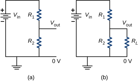
72. The rather simple circuit shown below is known as a voltage divider. The symbol consisting of three horizontal lines is represents “ground” and can be defined as the point where the potential is zero. The voltage divider is widely used in circuits and a single voltage source can be used to provide reduced voltage to a load resistor as shown in the second part of the figure. (a) What is the output voltage Vout of circuit
(a) in terms of R1,R2, and Vin?
(b) What is the output voltage Vout of circuit (b) in terms of R1,R2,RL, and Vin?
73. Three 300-Ω resistors are connect in series with an AAA battery with a rating of 3 AmpHours. (a) How long can the battery supply the resistors with power? (b) If the resistors are connected in parallel, how long can the battery last?
74. Consider a circuit that consists of a real battery with an emf εε and an internal resistance of r connected to a variable resistor R.
(a) In order for the terminal voltage of the battery to be equal to the emf of the battery, what should the resistance of the variable resistor be adjusted to?
(b) In order to get the maximum current from the battery, what should the resistance of the variable resistor be adjusted to?
(c) In order for the maximum power output of the battery to be reached, what should the resistance of the variable resistor be set to?
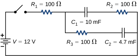
75. Consider the circuit shown below. What is the energy stored in each capacitor after the switch has been closed for a very long time?
76. Consider a circuit consisting of a battery with an emf εε and an internal resistance of r connected in series with a resistorR and a capacitor C. Show that the total energy supplied by the battery while charging the battery is equal to ε2C.
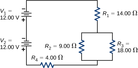
77. Consider the circuit shown below. The terminal voltages of the batteries are shown.
(a) Find the equivalent resistance of the circuit and the current out of the battery.
(b) Find the current through each resistor.
(c) Find the potential drop across each resistor.
(d) Find the power dissipated by each resistor.
(e) Find the total power supplied by the batteries.
78. Consider the circuit shown below.
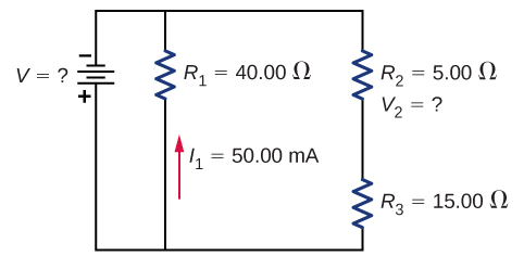
(a) What is the terminal voltage of the battery?
(b) What is the potential drop across resistor R2?
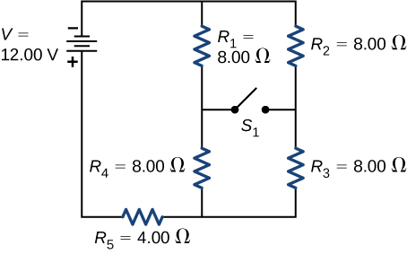
79. Consider the circuit shown below.
(a)Determine the equivalent resistance and the current from the battery with switch S1open.
(b) Determine the equivalent resistance and the current from the battery with switch S1 closed.
80. Two resistors, one having a resistance of 145Ω, are connected in parallel to produce a total resistance of 150Ω.
(a) What is the value of the second resistance?
(b) What is unreasonable about this result?
(c) Which assumptions are unreasonable or inconsistent?
81. Two resistors, one having a resistance of 900kΩ, are connected in series to produce a total resistance of 0.500MΩ.
(a) What is the value of the second resistance?
(b) What is unreasonable about this result?
(c) Which assumptions are unreasonable or inconsistent?
82. Apply the junction rule at point a shown below.
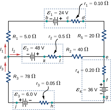
83. Apply the loop rule to Loop akledcba in the preceding problem.
84. Find the currents flowing in the circuit in the preceding problem. Explicitly show how you follow the steps in the Problem-Solving Strategy: Series and Parallel Resistors.
85. Consider the circuit shown below.
(a) Find the current through each resistor.
(b) Check the calculations by analyzing the power in the circuit.
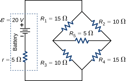
86. A flashing lamp in a Christmas earring is based on an RC discharge of a capacitor through its resistance. The effective duration of the flash is 0.250 s, during which it produces an average 0.500 W from an average 3.00 V.
(a) What energy does it dissipate?
(b) How much charge moves through the lamp?
(c) Find the capacitance.
(d) What is the resistance of the lamp? (Since average values are given for some quantities, the shape of the pulse profile is not needed.)
87. A 160-μF capacitor charged to 450 V is discharged through a 31.2-kΩ resistor.
(a) Find the time constant.
(b) Calculate the temperature increase of the resistor, given that its mass is 2.50 g and its specific heat is 1.67kJ/kg⋅°C, noting that most of the thermal energy is retained in the short time of the discharge.
(c) Calculate the new resistance, assuming it is pure carbon.
(d) Does this change in resistance seem significant?
Challenge Problems
88. Some camera flashes use flash tubes that require a high voltage. They obtain a high voltage by charging capacitors in parallel and then internally changing the connections of the capacitors to place them in series. Consider a circuit that uses four AAA batteries connected in series to charge six 10-mF capacitors through an equivalent resistance of 100Ω. The connections are then switched internally to place the capacitors in series. The capacitors discharge through a lamp with a resistance of 100Ω.
(a) What is the RC time constant and the initial current out of the batteries while they are connected in parallel?
(b) How long does it take for the capacitors to charge to 90% of the terminal voltages of the batteries?
(c) What is the RC time constant and the initial current of the capacitors connected in series assuming it discharges at 90%90% of full charge?
(d) How long does it take the current to decrease to 10% of the initial value?
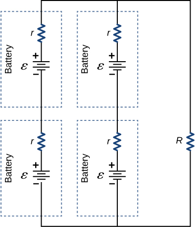
89. Consider the circuit shown below. Each battery has an emf of 1.50 V and an internal resistance of 1.00Ω.
(a) What is the current through the external resistor, which has a resistance of 10.00 ohms?
(b) What is the terminal voltage of each battery?
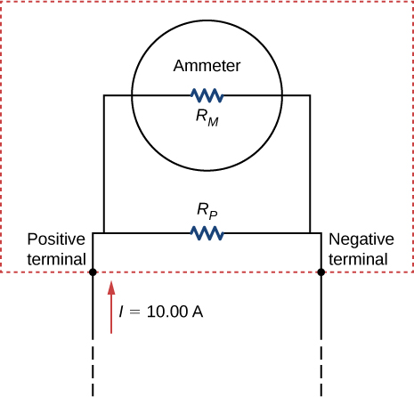
90. Analog meters use a galvanometer, which essentially consists of a coil of wire with a small resistance and a pointer with a scale attached. When current runs through the coil, the pointer turns; the amount the pointer turns is proportional to the amount of current running through the coil. Galvanometers can be used to make an ammeter if a resistor is placed in parallel with the galvanometer. Consider a galvanometer that has a resistance of 25.00Ω and gives a full scale reading when a 50-μA current runs through it. The galvanometer is to be used to make an ammeter that has a full scale reading of 10.00 A, as shown below. Recall that an ammeter is connected in series with the circuit of interest, so all 10 A must run through the meter.
(a) What is the current through the parallel resistor in the meter?
(b) What is the voltage across the parallel resistor?
(c) What is the resistance of the parallel resistor?
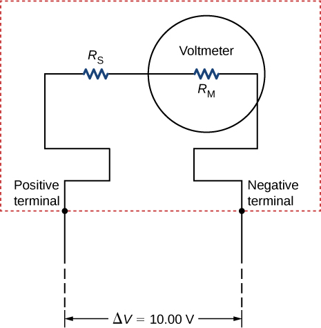
91. Analog meters use a galvanometer, which essentially consists of a coil of wire with a small resistance and a pointer with a scale attached. When current runs through the coil, the point turns; the amount the pointer turns is proportional to the amount of current running through the coil. Galvanometers can be used to make a voltmeter if a resistor is placed in series with the galvanometer. Consider a galvanometer that has a resistance of 25.00Ω and gives a full scale reading when a 50-μA current runs through it. The galvanometer is to be used to make an voltmeter that has a full scale reading of 10.00 V, as shown below. Recall that a voltmeter is connected in parallel with the component of interest, so the meter must have a high resistance or it will change the current running through the component.
(a) What is the potential drop across the series resistor in the meter?
(b) What is the resistance of the parallel resistor?
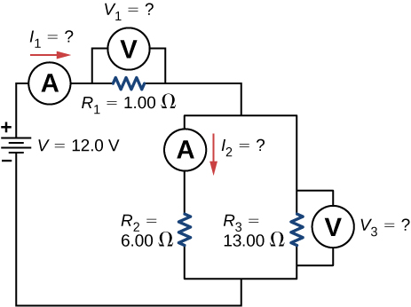
92. Consider the circuit shown below. Find I1,V1,I2, and V3.
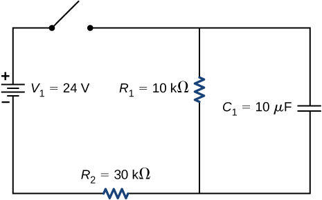
93. Consider the circuit below.
(a) What is the RC time constant of the circuit?
(b) What is the initial current in the circuit once the switch is closed?
(c) How much time passes between the instant the switch is closed and the time the current has reached half of the initial current?
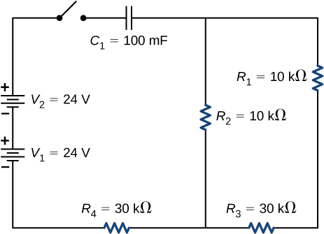
94. Consider the circuit below.
(a) What is the initial current through resistor R2 when the switch is closed?
(b) What is the current through resistor R2 when the capacitor is fully charged, long after the switch is closed?
(c) What happens if the switch is opened after it has been closed for some time?
(d) If the switch has been closed for a time period long enough for the capacitor to become fully charged, and then the switch is opened, how long before the current through resistor R1 reaches half of its initial value?
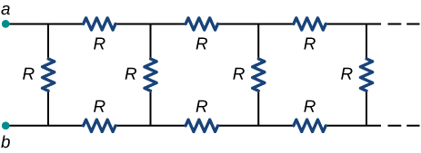
95. Consider the infinitely long chain of resistors shown below. What is the resistance between terminals a and b?
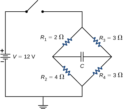
96. Consider the circuit below. The capacitor has a capacitance of 10 mF. The switch is closed and after a long time the capacitor is fully charged.
(a) What is the current through each resistor a long time after the switch is closed?
(b) What is the voltage across each resistor a long time after the switch is closed?
(c) What is the voltage across the capacitor a long time after the switch is closed?
(d) What is the charge on the capacitor a long time after the switch is closed?
(e) The switch is then opened. The capacitor discharges through the resistors. How long from the time before the current drops to one fifth of the initial value?
97. A 120-V immersion heater consists of a coil of wire that is placed in a cup to boil the water. The heater can boil one cup of 20.00°C water in 180.00 seconds. You buy one to use in your dorm room, but you are worried that you will overload the circuit and trip the 15.00-A, 120-V circuit breaker, which supplies your dorm room. In your dorm room, you have four 100.00-W incandescent lamps and a 1500.00-W space heater.
(a) What is the power rating of the immersion heater?
(b) Will it trip the breaker when everything is turned on?
(c) If it you replace the incandescent bulbs with 18.00-W LED, will the breaker trip when everything is turned on?
98. Find the resistance that must be placed in series with a 25.0-Ω galvanometer having a 50.0-μA sensitivity (the same as the one discussed in the text) to allow it to be used as a voltmeter with a 3000-V full-scale reading. Include a circuit diagram with your solution.
99. Find the resistance that must be placed in parallel with a 60.0-Ω galvanometer having a 1.00-mA sensitivity (the same as the one discussed in the text) to allow it to be used as an ammeter with a 25.0-A full-scale reading. Include a circuit diagram with your solution.


