18.2: Equipotential Surfaces and Lines
- Page ID
- 14551
learning objectives
- Compare conductivity and resistivity of an ideal conductor, commenting on the presence of ideal conductors in nature
An ideal conductor is one that exists only in the world of theory. It is one that has certain “ideal” properties that make calculations of electric potential and field, and other properties simple to perform; it essentially eliminates the need for “corrections” to account for slight deviations from the so-called “ideal. ” These ideal properties are:
\[\mathrm{\sigma = \infty}\]
Conductivity (σ) is the inverse of resistance, measured in units of current per potential difference. In an ideal conductor, the material’s conductivity is infinite, and its resistance approaches 0. This means that, ideally, it needs a minute amount of voltage (potential difference) to carry an extremely high amperage (current). The principle of near-zero resistance is akin to that of frictionless surfaces: t. Theoretically, with the slightest force (voltage), an object (current) on a frictionless surface (zero-resistance conductor) can proceed without restriction.
\[\mathrm{E_{tan} = D_{tan} = 0}\]
The electric field (Etan) and electric flux density (Dtan) tangential to the surface of a conductor must be equal to 0. This is because any such field or flux that is tangential to the surface of the conductor must also exist inside the conductor, which by definition touches the tangential field or density at one point.
If an electric field exists inside the metal, there must be a drop in voltage between any two points along the surface of the metal. In a perfect conductor this drop should not exist because it implies a less-than-infinite conductivity.
\[\mathrm{D_n = Charge \; Density_{surface}}\]
Electric flux density normal to the conductor’s surface is equal to surface charge density. Essentially this means that the conductor’s charge exists on its surface, not in its interior.
\[\mathrm{\overrightarrow{E}_{int} = 0}\]
This means that the electric field inside a perfect conductor is 0. The charges along the surface all act equally and opposite to one another, and their sum at any point is equal to 0.
\[\mathrm{\Phi_{surface} = constant}\]
Charge distribution may vary depending on shape, but the potential over the surface of an ideal conductor is, at electrostatic equilibrium, constant throughout.
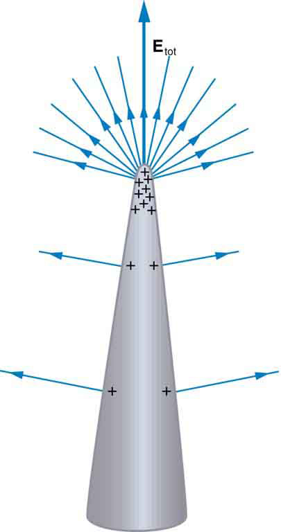
Charge Distribution on a Conductor with an Irregular Surface: Curvature causes electric field lines to extend such that they further distance themselves from one another with increasing distance from the conductor surface. As such, charges (and field lines) aggregate around areas of curvature.
Electric Potential in Human
Electric potentials are commonly found in the body, across cell membranes and in the firing of neurons.
learning objectives
- Give examples of the electric potentials in human body
Electric potentials are not limited in function to inorganic processes. In fact, they can be commonly seen in living organisms. In humans, they are seen in cell membranes and nerve impulses in particular.
Cell Membranes
Cell membranes are only semipermeable; water can freely travel in and out, but ions can be selectively admitted passage across them. As a result, a cell can contain a concentration of a given ion that differs from that which exists outside. Thus, a potential, called the resting potential, is created on either side of the membrane.
Typical ions used to generate resting potential include potassium, chloride, and bicarbonate.
Resting membrane potential is approximately -95 mV in skeletal muscle cells, -60 mV in smooth muscle cells, -80 to -90 mV in astroglia, and -60 to -70 mV in neurons.
Potentials can change as ions move across the cell membrane. This can occur passively, as ions diffuse through ion channels in the membrane. No energy is required for this to occur, and therefore ions can only move from areas of higher concentration to those of lower concentration.
Active transport of ions across a cell membrane is also a possibility. This involves ion pumps using energy to push an ion from an area of lower concentration to one of higher concentration.
Nerve Impulses
When the brain decides on an action, it sends an impulse that cascades to the extremity where a muscle contracts.
Neurons receive an impulse at the dendrites. This impulse is passed through the axon, a long extension of the cell, in the form of an electrical potential created by differing concentrations of sodium and potassium ions on either side of a membrane in the axon.
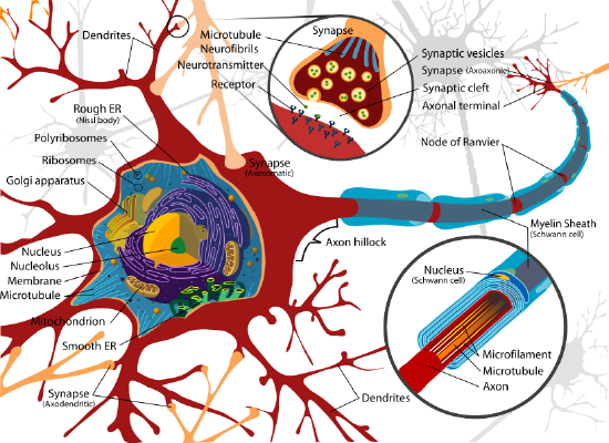
The Neuron: Neurons receive an impulse at the dendrites. This impulse is passed through the axon, a long extension of the cell, in the form of an electrical potential created by differing concentrations of sodium and potassium ions on either side of a membrane in the axon.
When the signal reaches the end of the axon, neurotransmitters are released, which then are received by the dendrites of the next neuron. The next neuron repeats the process outlined above.
Equipotential Lines
Equipotential lines depict one-dimensional regions in which the electric potential created by one or more nearby charges is constant.
learning objectives
- Describe the shape of the equipotential lines for several charge configurations
Equipotential lines depict one-dimensional regions in which the electric potential created by one or more nearby charges has a constant value. This means that if a charge is at any point on a given equipotential line, no work will be required to move it from one point to another on that same line.
Parallel Plates and Equipotential Lines: A brief overview of parallel plates and equipotential lines from the viewpoint of electrostatics.
Equipotential lines may be straight, curved, or irregularly shaped, depending on the orientation of charges that give rise to them. Since they are located radially around a charged body, they are perpendicular to electric field lines, which extend radially from the center of a charged body.
A Single Point Charge
For a single, isolated point charge, the formula for potential (V) is functionally dependent upon charge (Q) and inversely dependent upon radial distance from the charge (r):
\[\mathrm{V=\dfrac{kQ}{r}}\]
The radial dependence means that at any point a certain distance from the point charge, potential will be the same. Therefore, equipotential lines for a single point charge are circular, with the point charge at the center.
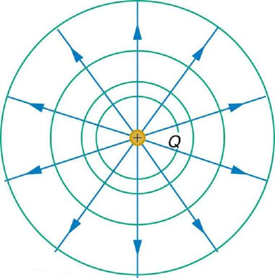
Equipotential Lines: An isolated point charge Q with its electric field lines (blue) and equipotential lines (green)
Multiple Point Charges
When multiple, discrete charges interact, their fields overlap. The combining of fields also results in a combining of potential, which results in the skewing of equipotential lines in areas that are close enough to both charges to “feel” the effects of both fields.
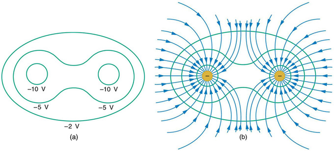
Equipotential lines with multiple charges: Equipotential lines become irregularly shaped when there are multiple charges vicinal to one another. At a point between the charges, a test charge may “feel” the effects of both charges.
Continuous Charge
If charges are distributed across two conductor plates in static equilibrium, in which charges are continuous and distributed in a straight line, the equipotential lines will be approximately straight. This is because the continuity of charges results in a continuity of action upon any point a certain distance from either plate.
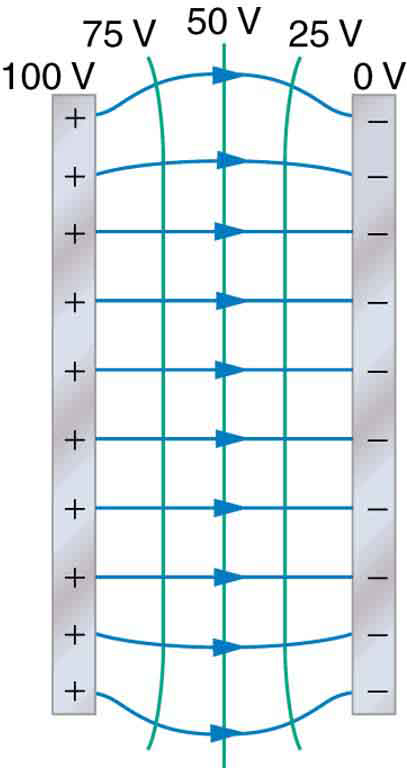
Equipotential Lines Between Two Plates: When charges are lined up and continuous on conducting plates, equipotential lines are straight between them. The only exception is a curving of the lines near the edges of the conductor plates.
This continuity is broken towards the ends of the plates, however, which causes curvature in these areas. This curvature is known as “edge effects. ”
Key Points
- In an ideal conductor, conductivity is assumed to be infinite (as resistivity approaches 0).
- The electric field (Etan) and electric flux density (Dtan) tangential to the surface of a conductor must be equal to 0.
- Electric flux density normal to the conductor’s surface is equal to surface charge density. Essentially this means that the conductor’s charge exists on its surface, not in its interior.
- Electric field inside a perfect conductor is 0. The charges along the surface all act equally and opposite to one another, and their sum at any point is equal to 0.
- Charge distribution may vary depending on shape, but the potential over the surface of an ideal conductor is, at electrostatic equilibrium, constant throughout.
- The resting potential is a potential created by an imbalance of ions on either side of a cell membrane.
- Resting potential can be altered by passive diffusion (which requires no energy ) or active transport of ions across a cell membrane.
- When the brain decides on an action, it sends an impulse that cascades to the extremity where a muscle contracts. Along the axon of a neuron, this impulse manifests itself in a potential created by an imbalance of sodium and potassium ions across a membrane.
- For a single, isolated point charge, potential is inversely dependent upon radial distance from the charge. Therefore, equipotential lines for a single point charge are circular, with the point charge at the center.
- When multiple, discrete charges interact, their fields overlap, meaning their potentials combine. This results in the skewing of equipotential lines in areas that are close enough to both charges to “feel” the effects of both fields.
- If charges are distributed across two conductor plates in static equilibrium, in which charges are continuous and distributed in a straight line, the equipotential lines will be approximately straight.
Key Terms
- conductor: A material which contains movable electric charges.
- flux density: A measure of rate of flow of a fluid, particles or energy per unit area.
- neuron: A cell of the nervous system, which conducts nerve impulses; consisting of an axon and several dendrites. Neurons are connected by synapses.
- axon: A nerve fiber which is a long, slender projection of a nerve cell, and which conducts nerve impulses away from the body of the cell to a synapse.
- cell membrane: The semipermeable membrane that surrounds the cytoplasm of a cell.
- equipotential: A region whose every point has the same potential.
- static equilibrium: the physical state in which all components of a system are at rest and the net force is equal to zero throughout the system
LICENSES AND ATTRIBUTIONS
CC LICENSED CONTENT, SHARED PREVIOUSLY
- Curation and Revision. Provided by: Boundless.com. License: CC BY-SA: Attribution-ShareAlike
CC LICENSED CONTENT, SPECIFIC ATTRIBUTION
- Electrical conductivity. Provided by: Wikipedia. Located at: en.Wikipedia.org/wiki/Electrical_conductivity. License: CC BY-SA: Attribution-ShareAlike
- conductor. Provided by: Wikipedia. Located at: en.Wikipedia.org/wiki/conductor. License: CC BY-SA: Attribution-ShareAlike
- flux density. Provided by: Wiktionary. Located at: en.wiktionary.org/wiki/flux_density. License: CC BY-SA: Attribution-ShareAlike
- OpenStax College, Conductors and Electric Fields in Static Equilibrium. January 9, 2013. Provided by: OpenStax CNX. Located at: http://cnx.org/content/m42317/latest/. License: CC BY: Attribution
- Neuron. Provided by: Wikipedia. Located at: en.Wikipedia.org/wiki/Neuron. License: CC BY-SA: Attribution-ShareAlike
- Resting potential. Provided by: Wikipedia. Located at: en.Wikipedia.org/wiki/Resting_potential. License: CC BY-SA: Attribution-ShareAlike
- neuron. Provided by: Wiktionary. Located at: en.wiktionary.org/wiki/neuron. License: CC BY-SA: Attribution-ShareAlike
- axon. Provided by: Wikipedia. Located at: en.Wikipedia.org/wiki/axon. License: CC BY-SA: Attribution-ShareAlike
- cell membrane. Provided by: Wiktionary. Located at: en.wiktionary.org/wiki/cell_membrane. License: CC BY-SA: Attribution-ShareAlike
- OpenStax College, Conductors and Electric Fields in Static Equilibrium. January 9, 2013. Provided by: OpenStax CNX. Located at: http://cnx.org/content/m42317/latest/. License: CC BY: Attribution
- Complete neuron cell diagram en. Provided by: Wikipedia. Located at: en.Wikipedia.org/wiki/File:Complete_neuron_cell_diagram_en.svg. License: CC BY-SA: Attribution-ShareAlike
- OpenStax College, Equipotential Lines. September 17, 2013. Provided by: OpenStax CNX. Located at: http://cnx.org/content/m42331/latest/. License: CC BY: Attribution
- equipotential. Provided by: Wiktionary. Located at: en.wiktionary.org/wiki/equipotential. License: CC BY-SA: Attribution-ShareAlike
- static equilibrium. Provided by: Wiktionary. Located at: en.wiktionary.org/wiki/static_equilibrium. License: CC BY-SA: Attribution-ShareAlike
- OpenStax College, Conductors and Electric Fields in Static Equilibrium. January 9, 2013. Provided by: OpenStax CNX. Located at: http://cnx.org/content/m42317/latest/. License: CC BY: Attribution
- Complete neuron cell diagram en. Provided by: Wikipedia. Located at: en.Wikipedia.org/wiki/File:Complete_neuron_cell_diagram_en.svg. License: CC BY-SA: Attribution-ShareAlike
- OpenStax College, Equipotential Lines. January 4, 2013. Provided by: OpenStax CNX. Located at: http://cnx.org/content/m42331/latest/. License: CC BY: Attribution
- OpenStax College, Equipotential Lines. January 4, 2013. Provided by: OpenStax CNX. Located at: http://cnx.org/content/m42331/latest/. License: CC BY: Attribution
- OpenStax College, Equipotential Lines. January 6, 2013. Provided by: OpenStax CNX. Located at: http://cnx.org/content/m42331/latest/. License: CC BY: Attribution
- Parallel Plates and Equipotential Lines. Located at: http://www.youtube.com/watch?v=EJ910SiVha0. License: Public Domain: No Known Copyright. License Terms: Standard YouTube license


