21.5: Magnetic Fields, Magnetic Forces, and Conductors
( \newcommand{\kernel}{\mathrm{null}\,}\)
learning objectives
- Express Hall voltage for a a metal containing only one type of charge carriers
The Hall effect is the phenomenon in which a voltage difference (called the Hall voltage) is produced across an electrical conductor, transverse to the conductor’s electric current when a magnetic field perpendicular to the conductor’s current is applied.
When a magnetic field is present that is not parallel to the motion of moving charges within a conductor, the charges experience the Lorentz force. In the absence of such a field, the charges follow a roughly straight path, occasionally colliding with impurities.
In the presence of a magnetic field with a perpendicular component, the paths charges take becomes curved such that they accumulate on one face of the material. On the other face, there is an excess of opposite charge remaining. Thus, an electric potential is created so long as the charge flows. This opposes the magnetic force, eventually to the point of cancelation, resulting in electron flow in a straight path.
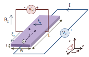
Hall Effect for Electrons: Initially, the electrons are attracted by the magnetic force and follow the curved arrow. Eventually, when electrons accumulate in excess on the left side and are in deficit on the right, an electric field ξy is created. This force becomes strong enough to cancel out the magnetic force, so future electrons follow a straight (rather than curved) path.
For a metal containing only one type of charge carrier (electrons), the Hall voltage (VH) can be calculated as a factor of current (I), magnetic field (B), thickness of the conductor plate (t), and charge carrier density (n) of the carrier electrons:
VH=−IBnet
In this formula, e represents the elementary charge.
The Hall coefficient (RH) is a characteristic of a conductor’s material, and is defined as the ratio of induced electric field (Ey) to the product of current density (jx) and applied magnetic field (B):
RH=EyjxB=VHtIB=−1ne
The Hall effect is a rather ubiquitous phenomenon in physics, and appears not only in conductors, but semiconductors, ionized gases, and in quantum spin among other applications.
Magnetic Force on a Current-Carrying Conductor
When an electrical wire is exposed to a magnet, the current in that wire will experience a force—the result of a magnet field.
learning objectives
- Express equation used to calculate the magnetic force for an electrical wire exposed to a magnetic field
When an electrical wire is exposed to a magnet, the current in that wire will be affected by a magnetic field. The effect comes in the form of a force. The expression for magnetic force on current can be found by summing the magnetic force on each of the many individual charges that comprise the current. Since they all run in the same direction, the forces can be added.
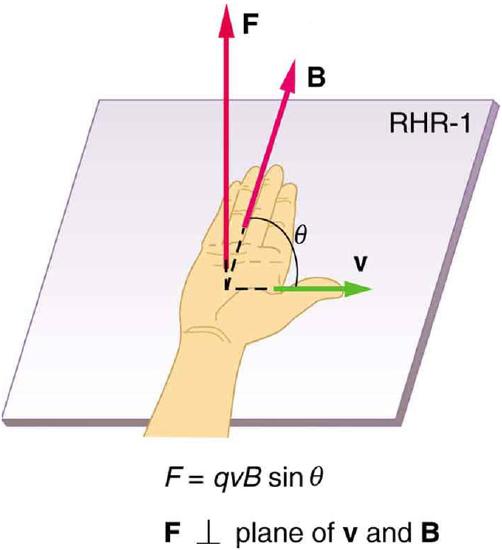
Right Hand Rule: Used to determine direction of magnetic force.
The force (F) a magnetic field (B) exerts on an individual charge (q) traveling at drift velocity vd is:
F=qvdBsinθ
In this instance, θ represents the angle between the magnetic field and the wire (magnetic force is typically calculated as a cross product). If B is constant throughout a wire, and is 0 elsewhere, then for a wire with N charge carriers in its total length l, the total magnetic force on the wire is:
F=NqvdBsinθ
Given that N=nV, where n is the number of charge carriers per unit volume and V is volume of the wire, and that this volume is calculated as the product of the circular cross-sectional area A and length (V=Al), yields the equation:
F=(nqAvd)lBsinθ
The terms in parentheses are equal to current (I), and thus the equation can be rewritten as:
F=IlBsinθ
The direction of the magnetic force can be determined using the right hand rule, demonstrated in. The thumb is pointing in the direction of the current, with the four other fingers parallel to the magnetic field. Curling the fingers reveals the direction of magnetic force.
Torque on a Current Loop: Rectangular and General
A current-carrying loop exposed to a magnetic field experiences a torque, which can be used to power a motor.
learning objectives
- Identify the general quation for the torque on a loop of any shape
When a current travels in a loop that is exposed to a magnetic field, that field exerts torque on the loop. This principle is commonly used in motors, in which the loop is connected to a shaft that rotates as a result of the torque. Thus, the electrical energy from the current is converted to mechanical energy as the loop and shaft rotate, and this mechanical energy is then used to power another device.
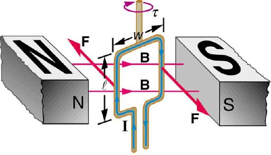
Torque on a Current Loop: Electrical energy from the current is converted to mechanical energy as the loop and shaft rotate, and this mechanical energy is then used to power another device.
In this model, the north and south poles of magnets are denoted by N and S, respectively. In the center is a rectangular wire loop of length l and width w, carrying current I. The effect of magnetic field B on the current-carrying wire exerts torque τ.
To understand the torque, we must analyze the forces acting on each segment of the loop. Assuming a constant magnetic field, we can conclude that the forces on the top and bottom parts of the loop are equal in magnitude and opposite in direction, and thus produce no net force. Incidentally, those forces are vertical and thus parallel to the shaft.
However, as illustrated by (a) in the figure below, the equal but opposite forces produce a torque that acts clockwise.
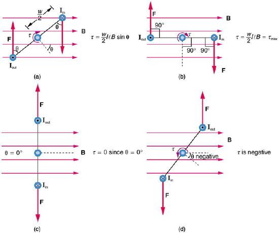
Varying torque on a charged loop in a magnetic field: Maximum torque occurs in (b), when is 90 degrees. Minimum torque is 0, and occurs in (c) when θ is 0 degrees. When loop rotates past =0, the torque reverses (d).
Given that torque is calculated from the equation:
τ=rFsinθ
where F is force on the rotating object, r is the distance from the pivot point that the force is applied, and θ is the angle between r and F, we can use the sum of two torques (the forces act on either side of the loop) to find the total torque:
τ=w2Fsinθ+w2Fsinθ=wFsinθ
Note that r is equal to w/2, as illustrated.
To find torque we still must solve for F from the magnetic field B on the current I. The rectangle has length l, so F=IlB. Replacing F with IlB in the torque equation gives:
τ=wIlBsinθ
Note that the product of w and l is included in this equation; those terms can be replaced with area (A) of the rectangle. If another shape of wire is used, its area can be inserted in the equation regardless of shape (whether circular, square, or otherwise).
Also note that this equation of torque is for a single turn. Torque increases proportionally according to number of turns (N). Thus, the general equation for torque on a loop of any shape, of N turns, each of A area, carrying I current and exposed to a magnetic field B is a value that fluctuates as the loop rotates, and can be calculated by:
τ=NIABsinθ
Ampere’s Law: Magnetic Field Due to a Long Straight Wire
Current running through a wire will produce a magnetic field that can be calculated using the Biot-Savart Law.
learning objectives
- Express the relationship between the strength of a magnetic field and a current running through a wire in a form of equation
Current running through a wire will produce both an electric field and a magnetic field. For a closed curve of length C, magnetic field (B) is related to current (IC) as in Ampere’s Law, stated mathematically as:
∮CBdℓ=μ0IC
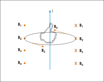
Direction of magnetic field: The direction of the magnetic field can be determined by the right hand rule.
In this equation, dl represents the differential of length of wire in the curved wire, and μ0 is the permeability of free space. This can be related to the Biot-Savart law. For a short, straight length of conductor (typically a wire) this law generally calculates partial magnetic field (dB) as a function of current for an infinitesimally small segment of wire (dl) at a point r distance away from the conductor:
dB=μ04πIdl×rr3
In this equation, the r vector can be written as r̂ (the unit vector in direction of r), if the r3 term in the denominator is reduced to r2 (this is simply reducing like terms in a fraction). Integrating the previous differential equation, we find:
B=μ04π∮CIdl׈rr2
This relationship holds for constant current in a straight wire, in which magnetic field at a point due to all current elements comprising the straight wire is the same. As illustrated in the direction of the magnetic field can be determined using the right hand rule—pointing one’s thumb in the direction of current, the curl of one’s fingers indicates the direction of the magnetic field around the straight wire.
Magnetic Force Between Two Parallel Conductors
Parallel wires carrying current produce significant magnetic fields, which in turn produce significant forces on currents.
learning objectives
- Express the magnetic force felt by a pair of wires in a form of an equation
Parallel wires carrying current produce significant magnetic fields, which in turn produce significant forces on currents. The force felt between the wires is used to define the the standard unit of current, know as an amphere.
In, the field (B1) that I1 creates can be calculated as a function of current and wire separation (r):
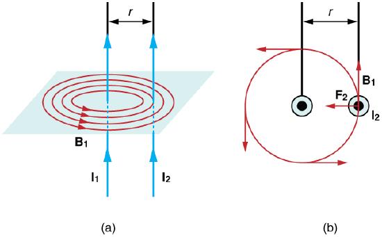
Magnetic fields and force exerted by parallel current-carrying wires.: Currents I1 and I2 flow in the same direction, separated by a distance of r.
B1=μ0I12πr
The field B1 exerts a force on the wire containing I2. In the figure, this force is denoted as F2.
The force F2 exerts on wire 2 can be calculated as:
F2=I2lB1sinθ
Given that the field is uniform along and perpendicular to wire 2, sin θ = sin 90 derees = 1. Thus the force simplifies to: F2=I2lB1
According to Newton’s Third Law (F1=-F2), the forces on the two wires will be equal in magnitude and opposite in direction, so to simply we can use F instead of F2. Given that wires are often very long, it’s often convenient to solve for force per unit length. Rearranging the previous equation and using the definition of B1gives:
F1=μ0I1I22πr
If the currents are in the same direction, the force attracts the wires. If the currents are in opposite directions, the force repels the wires.
The force between current-carrying wires is used as part of the operational definition of the ampere. For parallel wires placed one meter away from one another, each carrying one ampere, the force per meter is:
Fl=(4π⋅10−7T⋅m/A)(1A)2(2π)(1m)=2⋅10−7N/m
The final units come from replacing T with 1N/(A×m).
Incidentally, this value is the basis of the operational definition of the ampere. This means that one ampere of current through two infinitely long parallel conductors (separated by one meter in empty space and free of any other magnetic fields) causes a force of 2×10⁻⁷N/m on each conductor.
Key Points
- The Hall effect is the phenomenon in which a voltage difference (called the Hall voltage) is produced across an electrical conductor that is transverse to the conductor’s electric current when a magnetic field perpendicular to the conductor’s current is applied.
- Moving charges in a wire will change trajectory in the presence of a magnetic field, “bending” toward it. Thus, those charges accumulate on one face of the material. On the other face, there is left an excess of opposite charge. Thus, an electric potential is created.
- VH=−IBnet is the formula for Hall voltage (VH). It is a factor of current (I), magnetic field (B), thickness of the conductor plate (t), and charge carrier density (n) of the carrier electrons.
- Magnetic force on current can be found by summing the magnetic force on each of the individual charges that make this current.
- For a wire exposed to a magnetic field, τ=NIABsinθ describes the relationship between magnetic force (F), current (I), length of wire (l), magnetic field (B), and angle between field and wire (θ).
- The direction of the magnetic force can be determined using the right hand rule, as in fig .
- τ=NIABsinθ can be used to calculate torque (ττ) a loop of N turns and A area, carrying I current feels in the presence of a magnetic field B.
- Although the forces acting upon the loop are equal and opposite, they both act to rotate the loop in the same direction.
- Torque experienced is independent of the loop’s shape. What matters is the area of the loop.
- Ampere ‘s Law states that for a closed curve of length C, magnetic field (B) is related to current (IC): ∮CBdℓ=μ0IC. In this equation, dl represents the differential of length of wire in the curved wire, and μ0 is the permeability of free space.
- Ampere’s Law can be related to the Biot-Savart law, which holds for a short, straight length of conductor: dB=μ04πId×lrr3. In this equation, partial magnetic field (dB) is expressed as a function of current for an infinitesimally small segment of wire (dl) at a point r distance away from the conductor.
- After integrating, the direction of the magnetic field according to the Biot-Savart Law can be determined using the right hand rule.
- The field (B1) that that current (I1) from a wire creates can be calculated as a function of current and wire separation (r): B1=μ0I12πr μ0 is a constant.
- F=IlBsinθ describes the magnetic force felt by a pair of wires. If they are parallel the equation is simplified as the sine function is 1.
- The force felt between two parallel conductive wires is used to define the ampere —the standard unit of current.
Key Terms
- elementary charge: The electric charge on a single proton.
- transverse: Not tangent, so that a nondegenerate angle is formed between the two things intersecting.
- drift velocity: The average velocity of the free charges in a conductor.
- magnetic field: A condition in the space around a magnet or electric current in which there is a detectable magnetic force, and where two magnetic poles are present.
- torque: A rotational or twisting effect of a force; (SI unit newton-meter or Nm; imperial unit foot-pound or ft-lb)
- electric field: A region of space around a charged particle, or between two voltages; it exerts a force on charged objects in its vicinity.
- ampere: A unit of electrical current; the standard base unit in the International System of Units. Abbreviation: amp. Symbol: A.
- current: The time rate of flow of electric charge.
LICENSES AND ATTRIBUTIONS
CC LICENSED CONTENT, SHARED PREVIOUSLY
- Curation and Revision. Provided by: Boundless.com. License: CC BY-SA: Attribution-ShareAlike
CC LICENSED CONTENT, SPECIFIC ATTRIBUTION
- Hall effect. Provided by: Wikipedia. Located at: en.Wikipedia.org/wiki/Hall_effect. License: CC BY-SA: Attribution-ShareAlike
- transverse. Provided by: Wiktionary. Located at: en.wiktionary.org/wiki/transverse. License: CC BY-SA: Attribution-ShareAlike
- elementary charge. Provided by: Wiktionary. Located at: en.wiktionary.org/wiki/elementary_charge. License: CC BY-SA: Attribution-ShareAlike
- Hall Effect Measurement Setup for Electrons. Provided by: Wikipedia. Located at: en.Wikipedia.org/wiki/File:Hall_Effect_Measurement_Setup_for_Electrons.png. License: CC BY-SA: Attribution-ShareAlike
- OpenStax College, Magnetic Force on a Current-Carrying Conductor. September 17, 2013. Provided by: OpenStax CNX. Located at: http://cnx.org/content/m42398/latest/. License: CC BY: Attribution
- Boundless. Provided by: Boundless Learning. Located at: www.boundless.com//physics/definition/drift-velocity. License: CC BY-SA: Attribution-ShareAlike
- magnetic field. Provided by: Wiktionary. Located at: en.wiktionary.org/wiki/magnetic_field. License: CC BY-SA: Attribution-ShareAlike
- Hall Effect Measurement Setup for Electrons. Provided by: Wikipedia. Located at: en.Wikipedia.org/wiki/File:Hall_Effect_Measurement_Setup_for_Electrons.png. License: CC BY-SA: Attribution-ShareAlike
- OpenStax College, Magnetic Force on a Current-Carrying Conductor. January 12, 2013. Provided by: OpenStax CNX. Located at: http://cnx.org/content/m42398/latest/. License: CC BY: Attribution
- OpenStax College, Torque on a Current Loop: Motors and Meters. September 17, 2013. Provided by: OpenStax CNX. Located at: http://cnx.org/content/m42380/latest/. License: CC BY: Attribution
- torque. Provided by: Wiktionary. Located at: en.wiktionary.org/wiki/torque. License: CC BY-SA: Attribution-ShareAlike
- Hall Effect Measurement Setup for Electrons. Provided by: Wikipedia. Located at: en.Wikipedia.org/wiki/File:Hall_Effect_Measurement_Setup_for_Electrons.png. License: CC BY-SA: Attribution-ShareAlike
- OpenStax College, Magnetic Force on a Current-Carrying Conductor. January 12, 2013. Provided by: OpenStax CNX. Located at: http://cnx.org/content/m42398/latest/. License: CC BY: Attribution
- OpenStax College, Torque on a Current Loop: Motors and Meters. January 9, 2013. Provided by: OpenStax CNX. Located at: http://cnx.org/content/m42380/latest/. License: CC BY: Attribution
- OpenStax College, Torque on a Current Loop: Motors and Meters. January 9, 2013. Provided by: OpenStax CNX. Located at: http://cnx.org/content/m42380/latest/. License: CC BY: Attribution
- electric field. Provided by: Wiktionary. Located at: en.wiktionary.org/wiki/electric_field. License: CC BY-SA: Attribution-ShareAlike
- magnetic field. Provided by: Wiktionary. Located at: en.wiktionary.org/wiki/magnetic_field. License: CC BY-SA: Attribution-ShareAlike
- Sunil Kumar Singh, Magnetic Field Due to Current in Straight Wire. September 18, 2013. Provided by: OpenStax CNX. Located at: http://cnx.org/content/m31103/latest/. License: CC BY: Attribution
- Sunil Kumar Singh, Ampere's Law. September 18, 2013. Provided by: OpenStax CNX. Located at: http://cnx.org/content/m31895/latest/. License: CC BY: Attribution
- Biotu2013Savart law. Provided by: Wikipedia. Located at: en.Wikipedia.org/wiki/Biot%E2%80%93Savart_law. License: CC BY-SA: Attribution-ShareAlike
- Ampu00e8re's circuital law. Provided by: Wikipedia. Located at: en.Wikipedia.org/wiki/Amp%C3%A8re's_circuital_law. License: CC BY-SA: Attribution-ShareAlike
- Hall Effect Measurement Setup for Electrons. Provided by: Wikipedia. Located at: en.Wikipedia.org/wiki/File:Hall_Effect_Measurement_Setup_for_Electrons.png. License: CC BY-SA: Attribution-ShareAlike
- OpenStax College, Magnetic Force on a Current-Carrying Conductor. January 12, 2013. Provided by: OpenStax CNX. Located at: http://cnx.org/content/m42398/latest/. License: CC BY: Attribution
- OpenStax College, Torque on a Current Loop: Motors and Meters. January 9, 2013. Provided by: OpenStax CNX. Located at: http://cnx.org/content/m42380/latest/. License: CC BY: Attribution
- OpenStax College, Torque on a Current Loop: Motors and Meters. January 9, 2013. Provided by: OpenStax CNX. Located at: http://cnx.org/content/m42380/latest/. License: CC BY: Attribution
- Sunil Kumar Singh, Magnetic Field Due to Current in Straight Wire. January 12, 2013. Provided by: OpenStax CNX. Located at: http://cnx.org/content/m31103/latest/. License: CC BY: Attribution
- OpenStax College, Magnetic Force between Two Parallel Conductors. September 17, 2013. Provided by: OpenStax CNX. Located at: http://cnx.org/content/m42386/latest/. License: CC BY: Attribution
- ampere. Provided by: Wiktionary. Located at: en.wiktionary.org/wiki/ampere. License: CC BY-SA: Attribution-ShareAlike
- current. Provided by: Wiktionary. Located at: en.wiktionary.org/wiki/current. License: CC BY-SA: Attribution-ShareAlike
- magnetic field. Provided by: Wiktionary. Located at: en.wiktionary.org/wiki/magnetic_field. License: CC BY-SA: Attribution-ShareAlike
- Hall Effect Measurement Setup for Electrons. Provided by: Wikipedia. Located at: http://en.Wikipedia.org/wiki/File:Hall_Effect_Measurement_Setup_for_Electrons.png. License: CC BY-SA: Attribution-ShareAlike
- OpenStax College, Magnetic Force on a Current-Carrying Conductor. January 12, 2013. Provided by: OpenStax CNX. Located at: http://cnx.org/content/m42398/latest/. License: CC BY: Attribution
- OpenStax College, Torque on a Current Loop: Motors and Meters. January 9, 2013. Provided by: OpenStax CNX. Located at: http://cnx.org/content/m42380/latest/. License: CC BY: Attribution
- OpenStax College, Torque on a Current Loop: Motors and Meters. January 9, 2013. Provided by: OpenStax CNX. Located at: http://cnx.org/content/m42380/latest/. License: CC BY: Attribution
- Sunil Kumar Singh, Magnetic Field Due to Current in Straight Wire. January 12, 2013. Provided by: OpenStax CNX. Located at: http://cnx.org/content/m31103/latest/. License: CC BY: Attribution
- OpenStax College, Magnetic Force between Two Parallel Conductors. January 9, 2013. Provided by: OpenStax CNX. Located at: http://cnx.org/content/m42386/latest/. License: CC BY: Attribution

