26.1: Superposition and Interference
- Page ID
- 16191
\( \newcommand{\vecs}[1]{\overset { \scriptstyle \rightharpoonup} {\mathbf{#1}} } \)
\( \newcommand{\vecd}[1]{\overset{-\!-\!\rightharpoonup}{\vphantom{a}\smash {#1}}} \)
\( \newcommand{\dsum}{\displaystyle\sum\limits} \)
\( \newcommand{\dint}{\displaystyle\int\limits} \)
\( \newcommand{\dlim}{\displaystyle\lim\limits} \)
\( \newcommand{\id}{\mathrm{id}}\) \( \newcommand{\Span}{\mathrm{span}}\)
( \newcommand{\kernel}{\mathrm{null}\,}\) \( \newcommand{\range}{\mathrm{range}\,}\)
\( \newcommand{\RealPart}{\mathrm{Re}}\) \( \newcommand{\ImaginaryPart}{\mathrm{Im}}\)
\( \newcommand{\Argument}{\mathrm{Arg}}\) \( \newcommand{\norm}[1]{\| #1 \|}\)
\( \newcommand{\inner}[2]{\langle #1, #2 \rangle}\)
\( \newcommand{\Span}{\mathrm{span}}\)
\( \newcommand{\id}{\mathrm{id}}\)
\( \newcommand{\Span}{\mathrm{span}}\)
\( \newcommand{\kernel}{\mathrm{null}\,}\)
\( \newcommand{\range}{\mathrm{range}\,}\)
\( \newcommand{\RealPart}{\mathrm{Re}}\)
\( \newcommand{\ImaginaryPart}{\mathrm{Im}}\)
\( \newcommand{\Argument}{\mathrm{Arg}}\)
\( \newcommand{\norm}[1]{\| #1 \|}\)
\( \newcommand{\inner}[2]{\langle #1, #2 \rangle}\)
\( \newcommand{\Span}{\mathrm{span}}\) \( \newcommand{\AA}{\unicode[.8,0]{x212B}}\)
\( \newcommand{\vectorA}[1]{\vec{#1}} % arrow\)
\( \newcommand{\vectorAt}[1]{\vec{\text{#1}}} % arrow\)
\( \newcommand{\vectorB}[1]{\overset { \scriptstyle \rightharpoonup} {\mathbf{#1}} } \)
\( \newcommand{\vectorC}[1]{\textbf{#1}} \)
\( \newcommand{\vectorD}[1]{\overrightarrow{#1}} \)
\( \newcommand{\vectorDt}[1]{\overrightarrow{\text{#1}}} \)
\( \newcommand{\vectE}[1]{\overset{-\!-\!\rightharpoonup}{\vphantom{a}\smash{\mathbf {#1}}}} \)
\( \newcommand{\vecs}[1]{\overset { \scriptstyle \rightharpoonup} {\mathbf{#1}} } \)
\(\newcommand{\longvect}{\overrightarrow}\)
\( \newcommand{\vecd}[1]{\overset{-\!-\!\rightharpoonup}{\vphantom{a}\smash {#1}}} \)
\(\newcommand{\avec}{\mathbf a}\) \(\newcommand{\bvec}{\mathbf b}\) \(\newcommand{\cvec}{\mathbf c}\) \(\newcommand{\dvec}{\mathbf d}\) \(\newcommand{\dtil}{\widetilde{\mathbf d}}\) \(\newcommand{\evec}{\mathbf e}\) \(\newcommand{\fvec}{\mathbf f}\) \(\newcommand{\nvec}{\mathbf n}\) \(\newcommand{\pvec}{\mathbf p}\) \(\newcommand{\qvec}{\mathbf q}\) \(\newcommand{\svec}{\mathbf s}\) \(\newcommand{\tvec}{\mathbf t}\) \(\newcommand{\uvec}{\mathbf u}\) \(\newcommand{\vvec}{\mathbf v}\) \(\newcommand{\wvec}{\mathbf w}\) \(\newcommand{\xvec}{\mathbf x}\) \(\newcommand{\yvec}{\mathbf y}\) \(\newcommand{\zvec}{\mathbf z}\) \(\newcommand{\rvec}{\mathbf r}\) \(\newcommand{\mvec}{\mathbf m}\) \(\newcommand{\zerovec}{\mathbf 0}\) \(\newcommand{\onevec}{\mathbf 1}\) \(\newcommand{\real}{\mathbb R}\) \(\newcommand{\twovec}[2]{\left[\begin{array}{r}#1 \\ #2 \end{array}\right]}\) \(\newcommand{\ctwovec}[2]{\left[\begin{array}{c}#1 \\ #2 \end{array}\right]}\) \(\newcommand{\threevec}[3]{\left[\begin{array}{r}#1 \\ #2 \\ #3 \end{array}\right]}\) \(\newcommand{\cthreevec}[3]{\left[\begin{array}{c}#1 \\ #2 \\ #3 \end{array}\right]}\) \(\newcommand{\fourvec}[4]{\left[\begin{array}{r}#1 \\ #2 \\ #3 \\ #4 \end{array}\right]}\) \(\newcommand{\cfourvec}[4]{\left[\begin{array}{c}#1 \\ #2 \\ #3 \\ #4 \end{array}\right]}\) \(\newcommand{\fivevec}[5]{\left[\begin{array}{r}#1 \\ #2 \\ #3 \\ #4 \\ #5 \\ \end{array}\right]}\) \(\newcommand{\cfivevec}[5]{\left[\begin{array}{c}#1 \\ #2 \\ #3 \\ #4 \\ #5 \\ \end{array}\right]}\) \(\newcommand{\mattwo}[4]{\left[\begin{array}{rr}#1 \amp #2 \\ #3 \amp #4 \\ \end{array}\right]}\) \(\newcommand{\laspan}[1]{\text{Span}\{#1\}}\) \(\newcommand{\bcal}{\cal B}\) \(\newcommand{\ccal}{\cal C}\) \(\newcommand{\scal}{\cal S}\) \(\newcommand{\wcal}{\cal W}\) \(\newcommand{\ecal}{\cal E}\) \(\newcommand{\coords}[2]{\left\{#1\right\}_{#2}}\) \(\newcommand{\gray}[1]{\color{gray}{#1}}\) \(\newcommand{\lgray}[1]{\color{lightgray}{#1}}\) \(\newcommand{\rank}{\operatorname{rank}}\) \(\newcommand{\row}{\text{Row}}\) \(\newcommand{\col}{\text{Col}}\) \(\renewcommand{\row}{\text{Row}}\) \(\newcommand{\nul}{\text{Nul}}\) \(\newcommand{\var}{\text{Var}}\) \(\newcommand{\corr}{\text{corr}}\) \(\newcommand{\len}[1]{\left|#1\right|}\) \(\newcommand{\bbar}{\overline{\bvec}}\) \(\newcommand{\bhat}{\widehat{\bvec}}\) \(\newcommand{\bperp}{\bvec^\perp}\) \(\newcommand{\xhat}{\widehat{\xvec}}\) \(\newcommand{\vhat}{\widehat{\vvec}}\) \(\newcommand{\uhat}{\widehat{\uvec}}\) \(\newcommand{\what}{\widehat{\wvec}}\) \(\newcommand{\Sighat}{\widehat{\Sigma}}\) \(\newcommand{\lt}{<}\) \(\newcommand{\gt}{>}\) \(\newcommand{\amp}{&}\) \(\definecolor{fillinmathshade}{gray}{0.9}\)learning objectives
- Contrast the effects of constructive and destructive interference
Conditions for Wave Interference
Interference is a phenomenon in which two waves superimpose to form a resultant wave of greater or lesser amplitude. Its effects can be observed in all types of waves (for example, light, acoustic waves and water waves). Interference usually refers to the interaction of waves that are correlated (coherent) with each other because they originate from the same source, or they have the same or nearly the same frequency. When two or more waves are incident on the same point, the total displacement at that point is equal to the vector sum of the displacements of the individual waves. If a crest of one wave meets a crest of another wave of the same frequency at the same point, then the magnitude of the displacement is the sum of the individual magnitudes. This is constructive interference and occurs when the phase difference between the waves is a multiple of 2π. Destructive interference occurs when the crest of one wave meets a trough of another wave. In this case, the magnitude of the displacements is equal to the difference in the individual magnitudes, and occurs when this difference is an odd multiple of π. Examples of constructive and destructive interference are shown in. If the difference between the phases is intermediate between these two extremes, then the magnitude of the displacement of the summed waves lies between the minimum and maximum values.
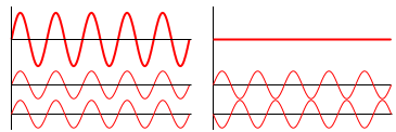
Wave Interference: Examples of constructive (left) and destructive (right) wave interference.
Wave Interference: A brief introduction to constructive and destructive wave interference and the principle of superposition.
A simple form of wave interference is observed when two waves of the same frequency (also called a plane wave) intersect at an angle, as shown in. Assuming the two waves are in phase at point B, then the relative phase changes along the x-axis. The phase difference at point A is given by:
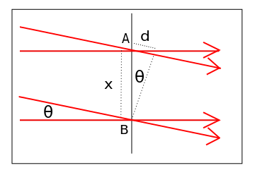
Interference of Plane Waves: Geometrical arrangement for two plane wave interference.
\[\Delta \varphi = \dfrac { 2 \pi \mathrm { d } } { \lambda } = \frac { 2 \pi \mathrm { x } \sin \theta } { \lambda }\]
Constructive interference occurs when the waves are in phase, or
\[\dfrac { x \sin \theta } { \lambda } = 0 , \pm 1 , \pm 2 , \ldots \]
Destructive interference occurs when the waves are half a cycle out of phase, or
\[\dfrac { x \sin \theta } { \lambda } = \pm \frac { 1 } { 2 } , \pm \frac { 3 } { 2 } , \ldots\]
Reflection Due to Phase Change
Light exhibits wave characteristics in various media as well as in a vacuum. When light goes from a vacuum to some medium (like water) its speed and wavelength change, but its frequency f remains the same. The speed of light in a medium is v = c/n, where n is the index of refraction. For example, water has an index of refraction of n = 1.333. When light is reflected off a medium with a higher index of refraction, crests get reflected as troughs and troughs get reflected as crests. In other words, the wave undergoes a 180 degree change of phase upon reflection, and the reflected ray “jumps” ahead by half a wavelength.
Air Wedge
An air wedge is a simple interferometer used to visualize the disturbance of the wave front after propagation through a test object.
learning objectives
- Describe how an air wedge is used to visualize the disturbance of a wave front after proagation
Air Wedge
An air wedge is one of the simplest designs of shearing interferometers used to visualize the disturbance of the wave front after propagation through a test object. An air wedge can be used with nearly any light source, including non-coherent white light. The interferometer consists of two optical glass wedges (~2-5 degrees), pushed together and then slightly separated from one side to create a thin air-gap wedge. An example of an air wedge interferometer is shown in.
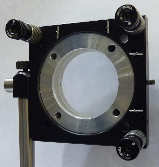
Air Wedge: Example of air wedge interferometer
The air gap between the two glass plates has two unique properties: it is very thin (micrometer scale) and has perfect flatness. Because of this extremely thin air-gap, the air wedge interferometer has been successfully used in experiments with femto-second high-power lasers.
An incident beam of light encounters four boundaries at which the index of refraction of the media changes, causing four reflected beams (or Fresnel reflections ) as shown in. The first reflection occurs when the beam enters the first glass plate. The second reflection occurs when the beam exits the first plate and enters the air wedge, and the third reflection occurs when the beam exits the air wedge and enters the second glass plate. The fourth beam is reflected when it encounters the boundary of the second glass plate. The air wedge angle, between the second and third Fresnel reflections, can be adjusted, causing the reflected light beams to constructively and destructively interfere and create a fringe pattern. To minimize image aberrations of the resulting fringes, the angle plane of the glass wedges has to be placed orthogonal to the angle plane of the air-wedge.
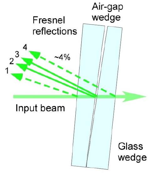
Light Reflections Inside an Air Wedge Interferometer: Beam path inside of air wedge interferometer
Newton’s Rings
Newton’s rings are a series of concentric circles centered at the point of contact between a spherical and a flat surface.
learning objectives
- Apply Newton’s rings to determine light characteristics of a lens
Newton’s Rings
In 1717, Isaac Newton first analyzed an interference pattern caused by the reflection of light between a spherical surface and an adjacent flat surface. Although first observed by Robert Hooke in 1664, this pattern is called Newton’s rings, as Newton was the first to analyze and explain the phenomena. Newton’s rings appear as a series of concentric circles centered at the point of contact between the spherical and flat surfaces. When viewed with monochromatic light, Newton’s rings appear as alternating bright and dark rings; when viewed with white light, a concentric ring pattern of rainbow colors is observed. An example of Newton’s rings when viewed with white light is shown in the figure below.
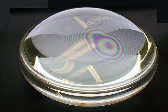
Newton’s Rings in a drop of water: Newton’s rings seen in two plano-convex lenses with their flat surfaces in contact. One surface is slightly convex, creating the rings. In white light, the rings are rainbow-colored, because the different wavelengths of each color interfere at different locations.
The light rings are caused by constructive interference between the light rays reflected from both surfaces, while the dark rings are caused by destructive interference. The outer rings are spaced more closely than the inner ones because the slope of the curved lens surface increases outwards. The radius of the Nth bright ring is given by:
\[\mathrm { r } _ { \mathrm { N } } = \left[ \left( \mathrm { N } - \dfrac { 1 } { 2 } \lambda \mathrm { R } \right) \right] ^ { 1 / 2 }\]
where N is the bright-ring number, R is the radius of curvature of the lens the light is passing through, and λ is the wavelength of the light passing through the glass.
A spherical lens is placed on top of a flat glass surface. An incident ray of light passes through the curved lens until it comes to the glass-air boundary, at which point it passes from a region of higher refractive index n (the glass) to a region of lower n (air). At this boundary, some light is transmitted into the air, while some light is reflected. The light that is transmitted into the air does not experience a change in phase and travels a a distance, d, before it is reflected at the flat glass surface below. This second air-glass boundary imparts a half-cycle phase shift to the reflected light ray because air has a lower n than the glass. The two reflected light rays now travel in the same direction to be detected. As one gets farther from the point at which the two surfaces touch, the distance dincreases because the lens is curving away from the flat surface.
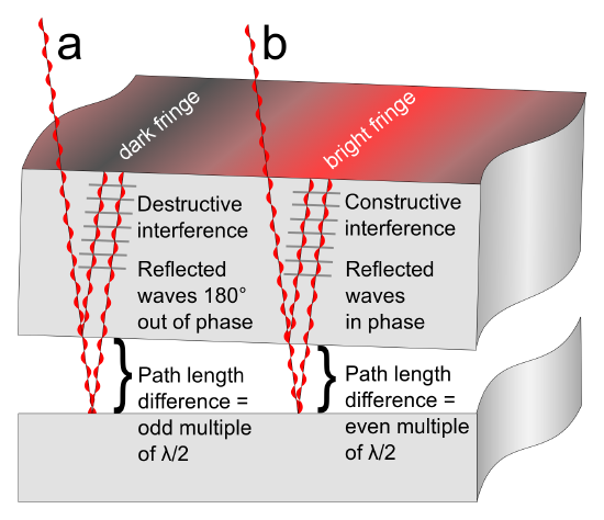
Formation of Interference Fringes: This figure shows how interference fringes form.
If the path length difference between the two reflected light beams is an odd multiple of the wavelength divided by two, λ/2, the reflected waves will be 180 degrees out of phase and destructively interfere, causing a dark fringe. If the path-length difference is an even multiple of λ/2, the reflected waves will be in phase with one another. The constructive interference of the two reflected waves creates a bright fringe.
Key Points
- When two or more waves are incident on the same point, the total displacement at that point is equal to the vector sum of the displacements of the individual waves.
- Light exhibits wave characteristics in various media as well as in a vacuum. When light goes from a vacuum to some medium, like water, its speed and wavelength change, but its frequency f remains the same.
- When light is reflected off a medium with a higher index of refraction, crests get reflected as troughs and troughs get reflected as crests. In other words, the wave undergoes a 180 degree change of phase upon reflection, and the reflected ray “jumps” ahead by half a wavelength.
- An air wedge interferometer consists of two optical glass wedges (~2-5 degrees), pushed together and then slightly separated from one side to create a thin air-gap wedge.
- The air gap between the two glass plates has two unique properties: it is very thin (micrometer scale) and has perfect flatness.
- To minimize image aberrations of the resulting fringes, the angle plane of the glass wedges has to be placed orthogonal to the angle plane of the air wedge.
- When viewed with monochromatic light, Newton’s rings appear as alternating bright and dark rings; when viewed with white light, a concentric ring pattern of rainbow colors is observed.
- If the path length difference between the two reflected light beams is an odd multiple of the wavelength divided by two, λ/2, the reflected waves will be 180 degrees out of phase and destructively interfere, causing a dark fringe.
- If the path length difference is an even multiple of λ/2, the reflected waves will be in-phase with one another. The constructive interference of the two reflected waves creates a bright fringe.
Key Terms
- coherent: Of waves having the same direction, wavelength and phase, as light in a laser.
- plane wave: A constant-frequency wave whose wavefronts (surfaces of constant phase) are infinite parallel planes of constant peak-to-peak amplitude normal to the phase velocity vector.
- orthogonal: Of two objects, at right angles; perpendicular to each other.
- interferometer: Any of several instruments that use the interference of waves to determine wavelengths and wave velocities, determine refractive indices, and measure small distances, temperature changes, stresses, and many other useful measurements.
- wavelength: The length of a single cycle of a wave, as measured by the distance between one peak or trough of a wave and the next; it is often designated in physics as λ, and corresponds to the velocity of the wave divided by its frequency.
- lens: an object, usually made of glass, that focuses or defocuses the light that passes through it
- monochromatic: Describes a beam of light with a single wavelength (i.e., of one specific color or frequency).
LICENSES AND ATTRIBUTIONS
CC LICENSED CONTENT, SHARED PREVIOUSLY
- Curation and Revision. Provided by: Boundless.com. License: CC BY-SA: Attribution-ShareAlike
CC LICENSED CONTENT, SPECIFIC ATTRIBUTION
- OpenStax College, College Physics. September 17, 2013. Provided by: OpenStax CNX. Located at: http://cnx.org/content/m42456/latest/?collection=col11406/1.7. License: CC BY: Attribution
- OpenStax College, College Physics. September 17, 2013. Provided by: OpenStax CNX. Located at: http://cnx.org/content/m42501/latest/?collection=col11406/1.7. License: CC BY: Attribution
- Interference (wave propagation). Provided by: Wikipedia. Located at: en.Wikipedia.org/wiki/Interference_(wave_propagation). License: CC BY-SA: Attribution-ShareAlike
- plane wave. Provided by: Wikipedia. Located at: en.Wikipedia.org/wiki/plane%20wave. License: CC BY-SA: Attribution-ShareAlike
- coherent. Provided by: Wiktionary. Located at: en.wiktionary.org/wiki/coherent. License: CC BY-SA: Attribution-ShareAlike
- Interference (wave propagation). Provided by: Wikipedia. Located at: en.Wikipedia.org/wiki/Interference_(wave_propagation). License: Public Domain: No Known Copyright
- Interference (wave propagation). Provided by: Wikipedia. Located at: en.Wikipedia.org/wiki/Interference_(wave_propagation). License: Public Domain: No Known Copyright
- Wave Interference. Located at: http://www.youtube.com/watch?v=tsmwLFgibT4. License: Public Domain: No Known Copyright. License Terms: Standard YouTube license
- Air-wedge shearing interferometer. Provided by: Wikipedia. Located at: en.Wikipedia.org/wiki/Air-wedge_shearing_interferometer. License: CC BY-SA: Attribution-ShareAlike
- interferometer. Provided by: Wiktionary. Located at: en.wiktionary.org/wiki/interferometer. License: CC BY-SA: Attribution-ShareAlike
- orthogonal. Provided by: Wiktionary. Located at: en.wiktionary.org/wiki/orthogonal. License: CC BY-SA: Attribution-ShareAlike
- Interference (wave propagation). Provided by: Wikipedia. Located at: en.Wikipedia.org/wiki/Interference_(wave_propagation). License: Public Domain: No Known Copyright
- Interference (wave propagation). Provided by: Wikipedia. Located at: en.Wikipedia.org/wiki/Interference_(wave_propagation). License: Public Domain: No Known Copyright
- Wave Interference. Located at: http://www.youtube.com/watch?v=tsmwLFgibT4. License: Public Domain: No Known Copyright. License Terms: Standard YouTube license
- Air-wedge shearing interferometer. Provided by: Wikipedia. Located at: en.Wikipedia.org/wiki/Air-wedge_shearing_interferometer. License: Public Domain: No Known Copyright
- Air-wedge shearing interferometer. Provided by: Wikipedia. Located at: en.Wikipedia.org/wiki/Air-wedge_shearing_interferometer. License: Public Domain: No Known Copyright
- Newton's rings. Provided by: Wikipedia. Located at: en.Wikipedia.org/wiki/Newton's_rings. License: CC BY-SA: Attribution-ShareAlike
- lens. Provided by: Wiktionary. Located at: en.wiktionary.org/wiki/lens. License: CC BY-SA: Attribution-ShareAlike
- wavelength. Provided by: Wiktionary. Located at: en.wiktionary.org/wiki/wavelength. License: CC BY-SA: Attribution-ShareAlike
- Boundless. Provided by: Boundless Learning. Located at: www.boundless.com//physics/definition/monochromatic. License: CC BY-SA: Attribution-ShareAlike
- Interference (wave propagation). Provided by: Wikipedia. Located at: en.Wikipedia.org/wiki/Interference_(wave_propagation). License: Public Domain: No Known Copyright
- Interference (wave propagation). Provided by: Wikipedia. Located at: en.Wikipedia.org/wiki/Interference_(wave_propagation). License: Public Domain: No Known Copyright
- Wave Interference. Located at: http://www.youtube.com/watch?v=tsmwLFgibT4. License: Public Domain: No Known Copyright. License Terms: Standard YouTube license
- Air-wedge shearing interferometer. Provided by: Wikipedia. Located at: en.Wikipedia.org/wiki/Air-wedge_shearing_interferometer. License: Public Domain: No Known Copyright
- Air-wedge shearing interferometer. Provided by: Wikipedia. Located at: en.Wikipedia.org/wiki/Air-wedge_shearing_interferometer. License: Public Domain: No Known Copyright
- Newton's rings. Provided by: Wikipedia. Located at: en.Wikipedia.org/wiki/Newton's_rings. License: Public Domain: No Known Copyright
- Newton's rings. Provided by: Wikipedia. Located at: en.Wikipedia.org/wiki/Newton's_rings. License: Public Domain: No Known Copyright

