3.3: Conservation Laws
- Page ID
- 29886
\( \newcommand{\vecs}[1]{\overset { \scriptstyle \rightharpoonup} {\mathbf{#1}} } \)
\( \newcommand{\vecd}[1]{\overset{-\!-\!\rightharpoonup}{\vphantom{a}\smash {#1}}} \)
\( \newcommand{\dsum}{\displaystyle\sum\limits} \)
\( \newcommand{\dint}{\displaystyle\int\limits} \)
\( \newcommand{\dlim}{\displaystyle\lim\limits} \)
\( \newcommand{\id}{\mathrm{id}}\) \( \newcommand{\Span}{\mathrm{span}}\)
( \newcommand{\kernel}{\mathrm{null}\,}\) \( \newcommand{\range}{\mathrm{range}\,}\)
\( \newcommand{\RealPart}{\mathrm{Re}}\) \( \newcommand{\ImaginaryPart}{\mathrm{Im}}\)
\( \newcommand{\Argument}{\mathrm{Arg}}\) \( \newcommand{\norm}[1]{\| #1 \|}\)
\( \newcommand{\inner}[2]{\langle #1, #2 \rangle}\)
\( \newcommand{\Span}{\mathrm{span}}\)
\( \newcommand{\id}{\mathrm{id}}\)
\( \newcommand{\Span}{\mathrm{span}}\)
\( \newcommand{\kernel}{\mathrm{null}\,}\)
\( \newcommand{\range}{\mathrm{range}\,}\)
\( \newcommand{\RealPart}{\mathrm{Re}}\)
\( \newcommand{\ImaginaryPart}{\mathrm{Im}}\)
\( \newcommand{\Argument}{\mathrm{Arg}}\)
\( \newcommand{\norm}[1]{\| #1 \|}\)
\( \newcommand{\inner}[2]{\langle #1, #2 \rangle}\)
\( \newcommand{\Span}{\mathrm{span}}\) \( \newcommand{\AA}{\unicode[.8,0]{x212B}}\)
\( \newcommand{\vectorA}[1]{\vec{#1}} % arrow\)
\( \newcommand{\vectorAt}[1]{\vec{\text{#1}}} % arrow\)
\( \newcommand{\vectorB}[1]{\overset { \scriptstyle \rightharpoonup} {\mathbf{#1}} } \)
\( \newcommand{\vectorC}[1]{\textbf{#1}} \)
\( \newcommand{\vectorD}[1]{\overrightarrow{#1}} \)
\( \newcommand{\vectorDt}[1]{\overrightarrow{\text{#1}}} \)
\( \newcommand{\vectE}[1]{\overset{-\!-\!\rightharpoonup}{\vphantom{a}\smash{\mathbf {#1}}}} \)
\( \newcommand{\vecs}[1]{\overset { \scriptstyle \rightharpoonup} {\mathbf{#1}} } \)
\(\newcommand{\longvect}{\overrightarrow}\)
\( \newcommand{\vecd}[1]{\overset{-\!-\!\rightharpoonup}{\vphantom{a}\smash {#1}}} \)
\(\newcommand{\avec}{\mathbf a}\) \(\newcommand{\bvec}{\mathbf b}\) \(\newcommand{\cvec}{\mathbf c}\) \(\newcommand{\dvec}{\mathbf d}\) \(\newcommand{\dtil}{\widetilde{\mathbf d}}\) \(\newcommand{\evec}{\mathbf e}\) \(\newcommand{\fvec}{\mathbf f}\) \(\newcommand{\nvec}{\mathbf n}\) \(\newcommand{\pvec}{\mathbf p}\) \(\newcommand{\qvec}{\mathbf q}\) \(\newcommand{\svec}{\mathbf s}\) \(\newcommand{\tvec}{\mathbf t}\) \(\newcommand{\uvec}{\mathbf u}\) \(\newcommand{\vvec}{\mathbf v}\) \(\newcommand{\wvec}{\mathbf w}\) \(\newcommand{\xvec}{\mathbf x}\) \(\newcommand{\yvec}{\mathbf y}\) \(\newcommand{\zvec}{\mathbf z}\) \(\newcommand{\rvec}{\mathbf r}\) \(\newcommand{\mvec}{\mathbf m}\) \(\newcommand{\zerovec}{\mathbf 0}\) \(\newcommand{\onevec}{\mathbf 1}\) \(\newcommand{\real}{\mathbb R}\) \(\newcommand{\twovec}[2]{\left[\begin{array}{r}#1 \\ #2 \end{array}\right]}\) \(\newcommand{\ctwovec}[2]{\left[\begin{array}{c}#1 \\ #2 \end{array}\right]}\) \(\newcommand{\threevec}[3]{\left[\begin{array}{r}#1 \\ #2 \\ #3 \end{array}\right]}\) \(\newcommand{\cthreevec}[3]{\left[\begin{array}{c}#1 \\ #2 \\ #3 \end{array}\right]}\) \(\newcommand{\fourvec}[4]{\left[\begin{array}{r}#1 \\ #2 \\ #3 \\ #4 \end{array}\right]}\) \(\newcommand{\cfourvec}[4]{\left[\begin{array}{c}#1 \\ #2 \\ #3 \\ #4 \end{array}\right]}\) \(\newcommand{\fivevec}[5]{\left[\begin{array}{r}#1 \\ #2 \\ #3 \\ #4 \\ #5 \\ \end{array}\right]}\) \(\newcommand{\cfivevec}[5]{\left[\begin{array}{c}#1 \\ #2 \\ #3 \\ #4 \\ #5 \\ \end{array}\right]}\) \(\newcommand{\mattwo}[4]{\left[\begin{array}{rr}#1 \amp #2 \\ #3 \amp #4 \\ \end{array}\right]}\) \(\newcommand{\laspan}[1]{\text{Span}\{#1\}}\) \(\newcommand{\bcal}{\cal B}\) \(\newcommand{\ccal}{\cal C}\) \(\newcommand{\scal}{\cal S}\) \(\newcommand{\wcal}{\cal W}\) \(\newcommand{\ecal}{\cal E}\) \(\newcommand{\coords}[2]{\left\{#1\right\}_{#2}}\) \(\newcommand{\gray}[1]{\color{gray}{#1}}\) \(\newcommand{\lgray}[1]{\color{lightgray}{#1}}\) \(\newcommand{\rank}{\operatorname{rank}}\) \(\newcommand{\row}{\text{Row}}\) \(\newcommand{\col}{\text{Col}}\) \(\renewcommand{\row}{\text{Row}}\) \(\newcommand{\nul}{\text{Nul}}\) \(\newcommand{\var}{\text{Var}}\) \(\newcommand{\corr}{\text{corr}}\) \(\newcommand{\len}[1]{\left|#1\right|}\) \(\newcommand{\bbar}{\overline{\bvec}}\) \(\newcommand{\bhat}{\widehat{\bvec}}\) \(\newcommand{\bperp}{\bvec^\perp}\) \(\newcommand{\xhat}{\widehat{\xvec}}\) \(\newcommand{\vhat}{\widehat{\vvec}}\) \(\newcommand{\uhat}{\widehat{\uvec}}\) \(\newcommand{\what}{\widehat{\wvec}}\) \(\newcommand{\Sighat}{\widehat{\Sigma}}\) \(\newcommand{\lt}{<}\) \(\newcommand{\gt}{>}\) \(\newcommand{\amp}{&}\) \(\definecolor{fillinmathshade}{gray}{0.9}\)Concepts and Principles
The Impulse-Momentum Relation
We’ve already used the impulse-momentum relation to analyze situations involving constant forces. The relation is typically applied in its component form:

Hopefully it’s not too much of a stretch to argue that for forces that vary in magnitude or direction the simple summation over a time interval (Dt) must be replaced by an integral over an infinitesimal time (dt):

Regardless of whether the forces acting on an object are constant or not, the impulse they exert on the object is precisely equal to the change in the object’s momentum.
The Work-Energy Relation
Our previous encounter with the work-energy relation resulted in:

where the forces acting on the object of interest were constant in both magnitude and direction. Again, for forces that vary, I will generalize this result to:

where the angle f is the angle between the instantaneous force acting on the object and the instantaneous displacement of the object (dr). Thus, this angle can change as the object moves along its path. Technically, this integral is termed a line integral and its evaluation can be rather complicated.
Also recall from our previous discussion of work-energy that this is not a vector equation, meaning it is not applied independently in each of the coordinate directions.
Analysis Tools
Applying the Impulse-Momentum Relation
Let’s re-examine the same situation we examined at the beginning of the previous chapter, a rocket launched directly upward with a time-dependent thrust.
A 2.0 kg toy rocket is fitted with an engine that provides a thrust roughly modeled by the function F(t) = (60 N/s) t – (15 N/s2) t2, for 0 < t < 4.0 s, and zero thereafter. The rocket is launched directly upward.
For analysis, we’ll apply the impulse-momentum relation between:
Event 1: The instant the rocket leaves the launch-pad.
Event 2: The instant the thrust drops to zero.
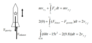
Remember from last chapter that the rocket does not leave the launch pad until 0.36 s after the engine is ignited.

When the engine shuts off, the rocket is traveling at 42.5 m/s upward.
We could also apply the impulse-momentum relation between:
Event 1: The instant the thrust drops to zero.
Event 2: The instant the rocket reaches its maximum height.
During this interval, the only force acting on the rocket is the force of gravity, and the impulse-momentum relation is:

Thus, the rocket reaches its highest altitude 8.34 s after launch.
It’s important to note that when a force is a function of time, it’s relatively easy to integrate the function and determine the impulse. However, it should be clear that it would not be easy to determine the work done by a force of this type. Since work is expressed as an integral of a force with respect to a displacement (dr), the force function has to be expressed in terms of position, r. In general, it’s not an easy (or sometimes possible) task to “convert” a function of time into a function of position, so work-energy is not a particularly useful way to analyze systems when the forces acting are time dependent. However, if the forces depend upon the position of the object, work-energy is a powerful analysis tool.
Applying the Work-Energy Relation
A 0.15 kg ball is launched vertically upward by means of a spring-loaded plunger, pulled back 8.0 cm and released. It requires a force of about 10 N to push the plunger back 8.0 cm.
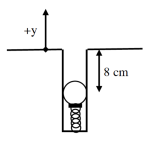
The Force Exerted by a SpringThe force that the spring exerts on the ball depends on the amount by which the spring is compressed. The more the spring is compressed, the larger the force it exerts on the ball. A common model is that the force exerted by a spring is directly proportional to the amount of deformation of the spring, in this case compression. Deformation (s) is defined to be the difference between the current length of the spring (L) and the equilibrium length (L0):

If we define the positive coordinate direction to point in the same direction as positive deformation (stretch), then

with the proportionality constant, k, referred to as the spring constant.
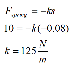
For the plunger, since it takes 10 N to compress the spring by 8.0 cm,
For analysis, we’ll apply the work-energy relation between:
Event 1: The instant the plunger is released.
Event 2: The instant the ball reaches its maximum height.
For these two events, work-energy looks like this:

To do the integral, we must express Fspring in terms of the variable of integration, y. For the coordinate system chosen, s and y are identical. Also note that the force of the spring and the direction of motion of the ball point in the same direction. Thus, f = 0.
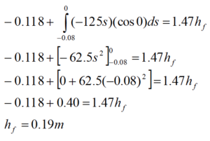
The ball reaches a maximum height of 19 cm above the top of the plunger.
Elastic Potential Energy
When an object interacts with a spring, or other elastic material, a common model is that the material reacts linearly, i.e., with a force directly proportional to the deformation of the material. It is possible to calculate the work done by the linear material in general, and to rewrite the work-energy relation in such a way as to incorporate the effects of this work from the start. This is referred to as constructing a potential energy function for the work done by the elastic material. We did exactly the same thing earlier for the force of gravity.
Imagine a spring of spring constant k, initially deformed by a distance si. It changes its deformation, ultimately resulting in deformation sf. To calculate the work done by the spring on the object causing the deformation:
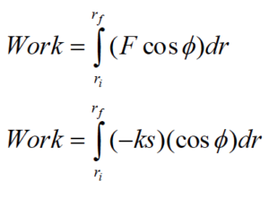
Choosing a coordinate system in which s and r are interchangeable (the origin is located at the point where the spring is at its natural length and the direction of elongation is positive) and allowing the force and the displacement to be in the same direction (f = 0) results in,

The terms, 1/2ks2, are referred to as elastic potential energy.
Inserting this result into the work-energy relation results in

with the understanding that the forces remaining in the equation, which may do work on the system, do not include the force of gravity or the force of the spring. The work done by the force of gravity and the force of the spring are already included in the relation via the inclusion of the potential energy terms.
Applying the Work-Energy Relation with Elastic Potential Energy
A 0.15 kg ball is launched vertically upward by means of a spring-loaded plunger, pulled back 8.0 cm and released. It requires a force of about 10 N to push the plunger back 8.0 cm.
The spring constant of the plunger is known to be 125 N/m from above. Applying the work-energy relation with potential energy terms between the instant the plunger is released and the instant the ball reaches its maximum height results in,

Of course, this results in the same answer as before.
Applying Newton’s Second Law to a Spring-Mass System
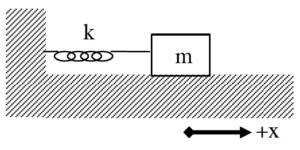 | Since we didn’t analyze systems involving springs in the previous dynamics section, we should make up for that omission now. The system at left consists of a spring with spring constant k attached to a block of mass m resting on a frictionless surface. The origin of the coordinate system is located at the position in which the spring is unstretched. |
Now imagine the block is pulled to the right and let go. Hopefully you can convince yourself that the block will oscillate back and forth. Let’s apply Newton’s Second Law at the instant the mass is at an arbitrary position, x. The only force acting on the mass in the x-direction is the force of the spring.

Because of our choice of coordinate system, the stretch of the spring (s) is exactly equal to the location of the block (x). Therefore,

Note that when the block is at a positive position, the force of the spring is in the negative direction and when the block is at a negative position, the force of the spring is in the positive direction. Thus, the force of the spring always acts to return the block to equilibrium.
Rearranging gives
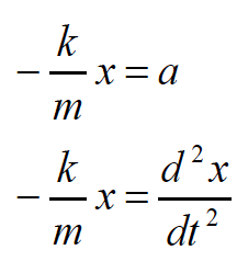
and defining a constant, w2, as

(Granted, it seems pretty silly to define k/m as the square of a constant, but just play along. You may also find it frustrating to learn that this “omega” is not an angular velocity. The block doesn’t even have an angular velocity!)
yields,

Therefore, the position function for the block must have a second time derivative equal to the product of (- w2) and itself. The only functions whose second time derivative is equal to the product of a negative constant and itself are the sine and the cosine functions. Therefore, a solution to this differential equation[1]

can be written:

or equivalently with the sine function, where A and f are arbitrary constants.[2]
- A is the amplitude of the oscillation. The amplitude is the maximum displacement of the object from equilibrium.
- φ is the phase angle. The phase angle is used to adjust the function forward or backward in time. For example, if the particle is at the origin at t = 0 s, f must equal +p/2 or -p/2 to ensure that the cosine function evaluates to zero at t = 0 s. If the particle is at its maximum position at t = 0 s, then the phase angle must be zero or p to ensure that the cosine function evaluates to +1 or -1 at t = 0 s.
- ω is the angular frequency of the oscillation.[3]
Note that the cosine function repeats itself when its argument increases by 2p. Thus, when

the function repeats. Since ω and φ are constant,

Therefore, the time interval when

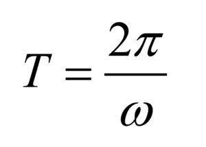
is the time interval for one complete cycle of the oscillatory motion. The time for one complete cycle of the motion is termed the period, T. Thus,
Therefore, the physical significance of the angular frequency is that it is inversely proportional to the period.
Substituting in the definition of w:

yields
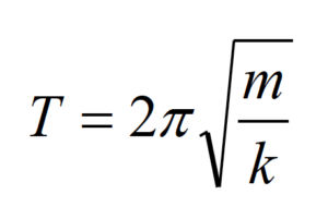
In summary, a mass attached to a spring will oscillate about its equilibrium position with a position function given by:

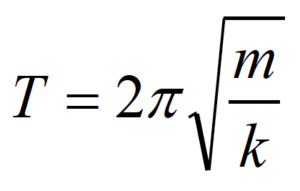
This function repeats with a period of
Potential Energy Functions
The potential energy functions for the work done by gravity and by springs make analyzing many situations much easier. In light of this, why don’t we construct potential energy functions for the work done by every different type of force that could possibly act on an object? Of course, one reason is that there are too many different types of forces. Having a potential energy function for the work done by every one of them would lead to so many potential energy functions that it would be hard to keep them all straight.
Another, more subtle reason is that it is impossible to construct potential energy functions for certain forces. A potential energy function must, by definition, be a function. Mathematically speaking, a potential energy function of position must assign a single, specific value of potential energy to every position. Functions must be single-valued. Notice that the gravitational and elastic potential energies are single valued. If you specify a height off of the ground, or the deformation of the spring, the potential energy function tells you exactly how much energy the system possesses at that position, regardless of the path the object took to reach that position.
In light of this observation, let’s try to create a potential energy function to replace the work done by friction.
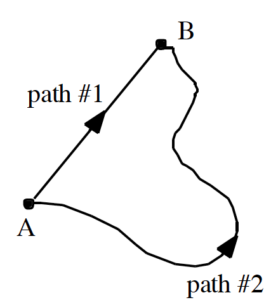 | Imagine sliding an object along a rough surface from point A to point B. If you slide the object along path #1, the force of friction will do a certain amount of work on the object. (This work will be negative because the direction of the force of friction is always in opposition to the change in position of the object.) If you slide the object along path #2, you should see that the magnitude of the work done by friction will be greater. (Although the frictional force will be the same in magnitude, the distance over which the frictional force acts will be larger. Thus, a larger amount of negative work will be done by friction.)
|
Now let’s try to create a potential energy function for the work done by friction. Since we are always free to choose a coordinate system, we can choose a system in which the potential energy at A is zero. What is the value for the potential energy at B? Since the work done by friction depends on the path taken from A to B, so must the potential energy. However, this leaves us with a potential energy at B that can be either one of two values, depending on the path taken! Since a function must be single-valued, the work done by friction cannot be represented by a function. You cannot create a potential energy function for the work done by friction!
There are also other forces whose work cannot be represented by a potential energy function. In general, forces whose work can be represented by a potential energy function are termed conservative forces, while those for which potential energy functions cannot be constructed are termed non-conservative.
Activities
For each of the scenarios described below, indicate the amount of kinetic energy, gravitational potential energy, and elastic energy in the system at each of the events listed. Use a consistent scale throughout both motions.
A 75 kg bungee jumper steps off a platform high above a raging river and plummets downward. The elastic bungee cord has an effective spring constant of 50 N/m and is initially slack, although it begins to stretch the moment the jumper steps off of the platform. Set the lowest point of the jumper as the zero-point of gravitational potential energy
A 75 kg bungee jumper steps off a platform high above a raging river and plummets downward. The elastic bungee cord has an effective spring constant of 50 N/m and is initially slack, although it begins to stretch the moment the jumper steps off of the platform. Set the platform as the zero-point of gravitational potential energy
For each of the scenarios described below, indicate the amount of kinetic energy, gravitational potential energy, and elastic energy in the system at each of the events listed. Use a consistent scale throughout each motion. Set the initial position of the object as the zero-point of gravitational potential energy
| A 0.27 kg toy car is held at rest against a 84 N/m compressed spring. When released, the car travels around a 0.30 m high loop. The car’s speed at the top of the loop is 2.2 m/s. Assume friction is so small that it can be ignored. | 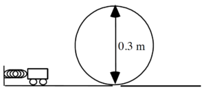 |
A 0.10 kg pinball is launched into a pinball machine by means of a plunger, pulled back 8.0 cm and released. The surface of the pinball machine is inclined at 130 from horizontal. Assume friction between the ball and the surface of the pinball machine during the launch of the ball is so small it can be ignored.
Six crates of different mass are hanging at rest from six springs. Each spring has a stiffness (k), a natural length (L0), and a current length (L). The natural length of the spring is its length before the crate is hung from it. The current length of the spring is its length when the crate is hung from it.
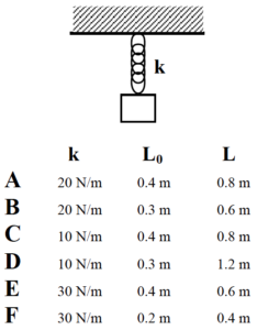
Rank the magnitude of the force of each spring acting on each crate.
Largest 1. _____ 2. _____ 3. _____ 4. _____ 5. _____ 6. _____ Smallest
_____ The ranking cannot be determined based on the information provided.
Explain the reason for your ranking:
Rank the mass of each crate.
Largest 1. _____ 2. _____ 3. _____ 4. _____ 5. _____ 6. _____ Smallest
_____ The ranking cannot be determined based on the information provided.
Explain the reason for your ranking:
Six crates of different mass (m) are attached to springs of different stiffness (k). The masses are held in place such that none of the springs are initially stretched. All springs are initially the same length. The masses are released and the springs stretch.
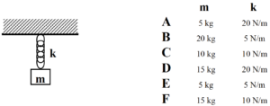
Rank the maximum elongation of the spring in each system.
Largest 1. _____ 2. _____ 3. _____ 4. _____ 5. _____ 6. _____ Smallest
_____ The ranking cannot be determined based on the information provided.
Rank the maximum speed of the crate in each system.
Largest 1. _____ 2. _____ 3. _____ 4. _____ 5. _____ 6. _____ Smallest
_____ The ranking cannot be determined based on the information provided.
Rank the maximum acceleration magnitude of the crate in each system.
Largest 1. _____ 2. _____ 3. _____ 4. _____ 5. _____ 6. _____ Smallest
_____ The ranking cannot be determined based on the information provided.
Explain the reason for your rankings:
Six identical mass crates are at rest on six springs. Each spring has a natural length (L0) and a current length (L). The natural length of the spring is its length before the crate is placed on top of it. The current length of the spring is its length when the crate is on top of it.
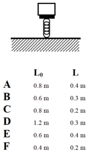
Rank the magnitude of the force of the spring acting on each crate.
Largest 1. _____ 2. _____ 3. _____ 4. _____ 5. _____ 6. _____ Smallest
_____ The ranking cannot be determined based on the information provided.
Explain the reason for your ranking:
Rank the stiffness of each spring.
Largest 1. _____ 2. _____ 3. _____ 4. _____ 5. _____ 6. _____ Smallest
_____ The ranking cannot be determined based on the information provided.
Explain the reason for your ranking:
Six crates of different mass (m) are at rest on six springs. Each spring has a natural length (L0) and a current length (L). The natural length of the spring is its length before the crate is placed on top of it. The current length of the spring is its length when the crate is on top of it.

Rank the stiffness of each spring.
Largest 1. _____ 2. _____ 3. _____ 4. _____ 5. _____ 6. _____ Smallest
_____ The ranking cannot be determined based on the information provided.
Explain the reason for your ranking:
Rank the elastic potential energy stored in each spring.
Largest 1. _____ 2. _____ 3. _____ 4. _____ 5. _____ 6. _____ Smallest
_____ The ranking cannot be determined based on the information provided.
Explain the reason for your ranking:
A pendulum of mass m is released from rest from an angle q from vertical. All pendulums are the same length.

Rank the maximum speed of each pendulum.
Largest 1. _____ 2. _____ 3. _____ 4. _____ 5. _____ 6. _____ Smallest
_____ The ranking cannot be determined based on the information provided.
Explain the reason for your ranking:
A pendulum of mass m is moving at velocity v as it passes through the vertical. All pendulums are the same length.

Rank the maximum angle from vertical reached by the pendulum.
Largest 1. _____ 2. _____ 3. _____ 4. _____ 5. _____ 6. _____ Smallest
_____ The ranking cannot be determined based on the information provided.
Explain the reason for your ranking:
A 100 kg rocket is fired vertically upward. Its engine supplies an upward force of magnitude F = (5000 – 5.0t2) N (where t is in seconds) until F = 0 N, then the engine shuts off.
How fast is the rocket moving when the engine shuts off?
| Free-Body Diagram | Mathematical Analysis[i]
Event 1: Event 2:
|
How long does it take the rocket to reach its maximum height?
| Free-Body Diagram | Mathematical Analysis
Event 1: Event 2:
|
A 75 kg rocket is launched directly upward. The force on the rocket due to its engine increases from 0 N to 5000 N over 8.0 s as a linear function of time. The thrust then drops to zero almost instantaneously.
How fast is the rocket moving when the engine shuts off?
| Free-Body Diagram | Mathematical Analysis[ii]
Event 1: Event 2:
|
How long does it take the rocket to reach its maximum height?
| Free-Body Diagram | Mathematical Analysis
Event 1: Event 2:
|
A 75 kg rocket is launched directly upward. The rocket is traveling at a speed of 200 m/s when its engine turns off. The force on the rocket due to its engine decreases to 0 N in 22 s as a quadratic function of time.
What is the maximum thrust acting on the rocket?
| Free-Body Diagram | Mathematical Analysis[iii]
Event 1: Event 2:
|
The horizontal thrust acting on a 270 kg rocket sled increases as a cubic function of time from 0 N to 5400 N in 4.3 s. The thrust then drops to zero almost instantaneously. The effective frictional coefficient acting between the rocket sled and the ground is (0.4, 0.3). The rocket sled starts from rest on a level surface.
How fast is the rocket sled moving when the engine shuts off?
| Free-Body Diagram | Mathematical Analysis[iv]
Event 1: Event 2:
|
The horizontal thrust acting on a 270 kg rocket sled decreases from 8000 N to 0 N as a quadratic function of time. The rocket sled is traveling at 195 m/s when the engine shuts down. The effective frictional coefficient acting between the rocket sled and the ground is (0.4, 0.3). The rocket sled starts from rest on a level surface.
What is the total elapsed time between the engine turning on and the sled ultimately coming to rest?
| Free-Body Diagram | Mathematical Analysis[v]
Event 1: Event 2:
|
A 75 kg bungee jumper is about to step off of a platform high above a raging river and plummet downward. The elastic bungee cord has an effective spring constant of 50 N/m and is initially slack, although it begins to stretch the moment the jumper steps off of the platform.
How far does the bungee jumper fall?
| Free-Body Diagram | Mathematical Analysis[vi]
Event 1: Event 2:
|
What is the maximum speed of the bungee jumper?
| Free-Body Diagram | Mathematical Analysis
Event 1: Event 2:
|
A 75 kg bungee jumper is about to step off of a platform 65 m above a raging river and plummet downward. He hopes to get just the top of his head wet. The elastic bungee cord acts as a linear spring and is initially slack, although it begins to stretch the moment the jumper steps off of the platform.
What is the spring constant of the bungee cord?
| Free-Body Diagram | Mathematical Analysis[vii]
Event 1: Event 2:
|
What is the maximum speed of the bungee jumper?
| Free-Body Diagram | Mathematical Analysis
Event 1: Event 2:
|
A 45 kg bungee jumper is about to step off of a platform 65 m above a raging river and plummet downward. She hopes to get just the top of her head wet. The elastic bungee cord acts as a linear spring and is initially slack. The cord does not begin to stretch until the jumper has fallen 10 m.
What is the spring constant of the bungee cord?
| Free-Body Diagram | Mathematical Analysis[viii]
Event 1: Event 2:
|
What is the maximum speed of the bungee jumper?
| Free-Body Diagram | Mathematical Analysis
Event 1: Event 2:
|
A 55 kg bungee jumper is about to step off of a platform 45 m above a raging river and plummet downward. She hopes to get just the top of her head wet. The elastic bungee cord acts as a linear spring with spring constant 30 N/m and is initially slack, but does not immediately begin to stretch when she steps off the platform.
How far can she safely fall before the bungee cord must begin to stretch?
| Free-Body Diagram | Mathematical Analysis[ix]
Event 1: Event 2:
|
How fast is she moving when she hits the river if she falls 15 m before the bungee cord begins to stretch?
| Free-Body Diagram | Mathematical Analysis
Event 1: Event 2:
|
A 0.10 kg pinball is launched into a pinball machine by means of a plunger, pulled back 8.0 cm and released. The surface of the pinball machine is inclined at 130 from horizontal. It requires a force of 12 N to pull the plunger back 5.0 cm. Assume friction between the ball and the surface of the pinball machine during the launch of the ball is so small it can be ignored.
What is the speed of the ball as it leaves the plunger?
| Free-Body Diagram | Mathematical Analysis[x]
Event 1: Event 2:
|
How far does the ball travel after leaving the plunger, assuming friction is small enough to be ignored?
| Free-Body Diagram | Mathematical Analysis
Event 1: Event 2:
|
At a UPS distribution center, a 40 kg crate is sliding down an 8° ramp at 3 m/s. At the bottom of the ramp, 8 m away, is a 150 N/m spring designed to bring the crate to rest. The coefficient of friction between the crate and the ramp is (0.2, 0.1).
What is the speed of the crate when it hits the spring?
| Free-Body Diagram | Mathematical Analysis[xi]
Event 1: Event 2:
|
How far does the spring compress before bringing the crate to rest?
| Free-Body Diagram | Mathematical Analysis
Event 1: Event 2:
|
| A 0.27 kg toy car is held at rest against a 84 N/m compressed spring. When released, the car travels around a 0.30 m high loop. The car’s speed at the top of the loop is 2.2 m/s. Assume friction is so small that it can be ignored. | 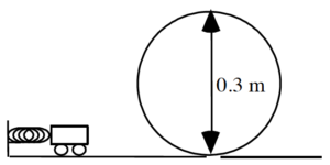 |
What is the initial compression of the launcher?
| Free-Body Diagram | Mathematical Analysis[xii]
Event 1: Event 2:
|
With what speed does the cart enter the loop?
| Free-Body Diagram | Mathematical Analysis
Event 1: Event 2:
|
A rocket of mass m is fired vertically upward. The interaction between its engine and the surroundings produces an upward force of magnitude F = Fmax – Ct2 N (where t is in seconds) until F = 0 N, then the engine shuts off. Determine the speed of the rocket at the instant the engine shuts off, voff, as a function of Fmax , C, m, and g.
| Free-Body Diagram | Mathematical Analysis
Event 1: Event 2:
|
Questions
If C = 0 N/s2, what should voff equal? Does your function agree with this observation?
If Fmax < mg, what should voff equal? Does your function agree with this observation?
A bungee jumper of mass m is about to step off of a platform a distance D above a rocky ravine and plummet downward. He hopes to not get the top of his head bloody. The elastic bungee cord acts as a linear spring and is initially slack. The cord does not begin to stretch until the jumper has fallen a distance d. Determine the minimum spring constant (k) needed for a safe jump as a function of m, g, D, and d.
| Free-Body Diagram | Mathematical Analysis
Event 1: Event 2:
|
Questions
If g = 0 m, what should k equal? Does your function agree with this observation?
If d = D, what should k equal? Does your function agree with this observation?
If m is twice as large, what effect will this have on k?
A pinball of mass m is launched into a pinball machine by means of a spring-driven plunger pulled back a distance s and released. The surface of the pinball machine is inclined at q from horizontal. Determine the speed of the ball as it leaves the plunger (v0) as a function of m, s, q , g, and the effective spring constant of the plunger system. Assume friction between the ball and the surface of the pinball machine during the launch of the ball is so small it can be ignored.
| Free-Body Diagram | Mathematical Analysis
Event 1: Event 2:
|
Questions
If s = 0 m, what should v0 equal? Does your function agree with this observation?
If k = 0 N/m, what should v0 equal? Does your function agree with this observation?
If the plunger is pulled back twice as far, what effect will this have on v0?
| A toy car of mass m is held at rest against a compressed spring. When released, the car travels around a loop. Determine the speed of the cart (v) as a function of the angular position of the cart on the loop (let straight down be q =0°), the spring constant (k), the initial compression of the spring (s), H, m, and g. Assume friction is so small that it can be ignored. | 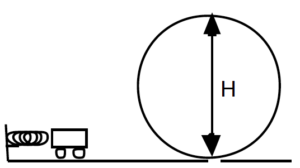 |
| Free-Body Diagram | Mathematical Analysis
Event 1: Event 2:
|
Questions
If s = 0 m, what should v equal? Does your function agree with this observation?
If k = 0 N/m, what should v equal? Does your function agree with this observation?
If q = 0°, what should v equal? Does your function agree with this observation?
[1] A differential equation is an equation involving a function and its derivative(s).
[2] To prove to yourself that this is indeed the solution to the equation, you should substitute the function, x(t), into the left side of the equation and the second derivative of x(t) into the right side. This will verify that the two sides of the equation are equal. In addition to mathematically verifying this solution, you should verify the solution physically by sketching a graph of the motion that you know would result if the block were displaced to the right and comparing that sketch to a sketch of the function.
[3] Again, note that w is not the angular velocity. The block is not rotating; it does not have an angular velocity.
[i] a. v2 = 746 m/s b. t3 = 107.7 s
[ii] a. v2 = 194 m/s b. t3 = 27.8 s
[iii] Fmax = 2125 N
[iv] v = 13.7 m/s
[v] t = 11.6 s
[vi] a. Dr = 29.4 m b. v2 = 12 m/s
[vii] a. k = 22.6 N/m b. v2 = 17.9 m/s
[viii] a. k = 19 N/m b. v2 = 20.6 m/s
[ix] a. d = 4.8 m b. v = 19.8 m/s
[x] a. v2 = 3.87 m/s b. Dr = 3.4 m
[xi] a. v2 = 3.91 m/s b. s = 2.13 m
[xii] a. s = 0.19 m b. v2 = 3.27 m/s
Homework 9 – Model 3: 105, 106, 107, 109, 110, 117, 118, 121.
- University Physics I Homework Assignments. Authored by: Mary Mohr. License: CC BY-NC-SA: Attribution-NonCommercial-ShareAlike


