

1.2: Current
- Page ID
- 148051

\( \newcommand{\vecs}[1]{\overset { \scriptstyle \rightharpoonup} {\mathbf{#1}} } \)
\( \newcommand{\vecd}[1]{\overset{-\!-\!\rightharpoonup}{\vphantom{a}\smash {#1}}} \)
\( \newcommand{\dsum}{\displaystyle\sum\limits} \)
\( \newcommand{\dint}{\displaystyle\int\limits} \)
\( \newcommand{\dlim}{\displaystyle\lim\limits} \)
\( \newcommand{\id}{\mathrm{id}}\) \( \newcommand{\Span}{\mathrm{span}}\)
( \newcommand{\kernel}{\mathrm{null}\,}\) \( \newcommand{\range}{\mathrm{range}\,}\)
\( \newcommand{\RealPart}{\mathrm{Re}}\) \( \newcommand{\ImaginaryPart}{\mathrm{Im}}\)
\( \newcommand{\Argument}{\mathrm{Arg}}\) \( \newcommand{\norm}[1]{\| #1 \|}\)
\( \newcommand{\inner}[2]{\langle #1, #2 \rangle}\)
\( \newcommand{\Span}{\mathrm{span}}\)
\( \newcommand{\id}{\mathrm{id}}\)
\( \newcommand{\Span}{\mathrm{span}}\)
\( \newcommand{\kernel}{\mathrm{null}\,}\)
\( \newcommand{\range}{\mathrm{range}\,}\)
\( \newcommand{\RealPart}{\mathrm{Re}}\)
\( \newcommand{\ImaginaryPart}{\mathrm{Im}}\)
\( \newcommand{\Argument}{\mathrm{Arg}}\)
\( \newcommand{\norm}[1]{\| #1 \|}\)
\( \newcommand{\inner}[2]{\langle #1, #2 \rangle}\)
\( \newcommand{\Span}{\mathrm{span}}\) \( \newcommand{\AA}{\unicode[.8,0]{x212B}}\)
\( \newcommand{\vectorA}[1]{\vec{#1}} % arrow\)
\( \newcommand{\vectorAt}[1]{\vec{\text{#1}}} % arrow\)
\( \newcommand{\vectorB}[1]{\overset { \scriptstyle \rightharpoonup} {\mathbf{#1}} } \)
\( \newcommand{\vectorC}[1]{\textbf{#1}} \)
\( \newcommand{\vectorD}[1]{\overrightarrow{#1}} \)
\( \newcommand{\vectorDt}[1]{\overrightarrow{\text{#1}}} \)
\( \newcommand{\vectE}[1]{\overset{-\!-\!\rightharpoonup}{\vphantom{a}\smash{\mathbf {#1}}}} \)
\( \newcommand{\vecs}[1]{\overset { \scriptstyle \rightharpoonup} {\mathbf{#1}} } \)
\(\newcommand{\longvect}{\overrightarrow}\)
\( \newcommand{\vecd}[1]{\overset{-\!-\!\rightharpoonup}{\vphantom{a}\smash {#1}}} \)
\(\newcommand{\ket}[1]{\left| #1 \right>}\)
\(\newcommand{\bra}[1]{\left< #1 \right|}\)
\(\newcommand{\braket}[2]{\left< #1 \vphantom{#2} \right| \left. #2 \vphantom{#1} \right>}\)
\(\newcommand{\braopket}[3]{\left< #1 \vphantom{#2}\vphantom{#3} \right| #2 \vphantom{#1}\vphantom{#3} \left| #3 \vphantom{#1}\vphantom{#2} \right>}\)
\(\newcommand{\qmvec}[1]{\mathbf{\vec{#1}}}\)
\(\newcommand{\op}[1]{\hat{\mathbf{#1}}}\)
\(\newcommand{\expect}[1]{\langle #1 \rangle}\)
\(\newcommand{\dfn}[1]{\emph{\textbf{#1}}}\)
1. Current
Learning Objectives
- Qualitatively show how resistors and junctions affect current in a circuit by annotating circuits to show comparative amounts of current along different paths.
- Calculate the current, resistance, and voltage change across resistors using Ohm’s Relation.
- Construct current equations for junctions using Kirchhoff’s Current Rule.
1.1 Charge and Current
Model
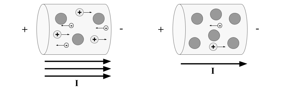
Two different resistors are connected to the same voltage source. In this model, we zoom in to see the microscopic differences.
Explore
- Identify the direction of each flow as from “+ to -” or from “- to +”.
- Negative Charges
- Positive Charges
- Current (\(I\))
- Which wire (left or right) has more current passing through it?
Critical Thinking & Concept Invention
- Which (left or right) model do you think it is easier for the charges to flow through? Why?
- Which model (left or right) do you think has more resistance? Why do you think that?
- Identify a Pattern:
When two resistors have the same change in voltage, the resistor with more resistance has __________ current.
Summary
The current in a circuit is based on the rate that charges flow through a circuit:
\(I \equiv \frac{dQ}{dt}\)
Typically negative charges are the ones that actually move through a circuit, but the current is defined as the direction of positive flow. This means that in most circuits, the current points in the opposite direction that the charges move.
The resistance of an object is based partly on the microscopic structure of that object (its resistivity). The geometry of the object (length and cross-sectional area) also affect the total resistance.
1.2 Kirchhoff Current Rule
Model

Explore
- How does the amount of current (number of arrows) in \(R_B\) compare to \(R_C\)?
- Examine each Kirchhoff Path and identify the amount of current (based on the number of arrows) in a given circuit element on each path. Also identify the current in and out of each junction.
| Path | Total Path Resistance | Number of Arrows Through Each Circuit Element |
|---|---|---|
| 1 | ||
| 2 |
- Examine each junction. Identify the number of arrows (amount of current) going into and out of each junction.
| Junction | Current (Number of Arrows) Going Into the Junction | Current (Number of Arrows) Coming Out of the Junction |
|---|---|---|
| 1 | ||
| 2 |
Critical Thinking & Concept Invention
- Identify trends:
- Resistors along the same path have (the same / different) amounts of current.
- Paths with more resistance have (more / less) current than paths with less resistance.
- Construct a rule:
At a junction, the current going into the junction __________________________________. - Circuit Models:
We show relative amounts of current in different parts of a circuit schematic by __________________________________.
Apply
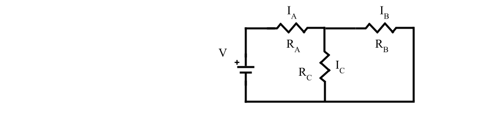
The circuit below has three resistors.
\(R_A > R_B\) and \(R_B = R_C\)
- Rank the current through each resistor (\(I_A\), \(I_B\), \(I_C\)) using \(>\), \(<\), and \(=\) signs.
- Rank the voltage drop across each resistor (\(\Delta V_A\), \(\Delta V_B\), \(\Delta V_C\)) using \(>\), \(<\), and \(=\) signs.
- Draw arrows next to each resistor to show the direction of current and compare the relative amount of current going through the resistor.

The circuit below has three resistors.
\(R_A > R_B\) and \(R_B > R_C\)
- Rank the current through each resistor (\(I_A\), \(I_B\), \(I_C\)) using \(>\), \(<\), and \(=\) signs.
- Construct a mathematical equation that relates the currents in all three resistors (\(I_A\), \(I_B\), \(I_C\)).
- Rank the voltage drop across each resistor (\(\Delta V_A\), \(\Delta V_B\), \(\Delta V_C\)) using \(>\), \(<\), and \(=\) signs.
- Draw arrows next to each resistor to show the direction of current and compare the relative amount of current going through the resistor.
1.3 Ohm’s Relation
Model

Explore
- Fill in the blanks to identify which quantity changed and if that caused the current to increase or decrease.
In Experiment 1, __________________ increased, which caused the current to __________________.
In Experiment 2, __________________ increased, which caused the current to __________________.
Critical Thinking & Concept Invention
- Select the appropriate proportionality:
\(I \propto \Delta V\)
OR
\(I \propto \frac{1}{\Delta V}\)
\(I \propto R\)
OR
\(I \propto \frac{1}{R}\)
- Combining the two proportionalities together gives an equation for current. Then rearrange that same equation to solve for the change in voltage.
\(I=\)
\(\Delta V=\)
Summary
The relationship between the voltage difference, resistance, and current is called Ohm’s Relation. It is only valid for resistors and gives the magnitude of those quantities. The sign (+/-) of the voltage difference is based on the direction of our Kirchhoff path through resistors, batteries, and other circuit elements.
Apply
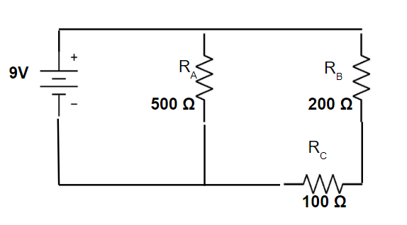
Mark up and analyze the circuit below:
- Draw two Kirchhoff Paths and add arrows for current near each junction (label them) and through each resistor. Verify that your arrows align with Kirchhoff’s Current Law and patterns relating current and resistance.
- Determine the Voltage Drop (\(\Delta V\)) for each resistor (remember Voltage Splitting).
- Use Ohm’s Relation to determine the current in each resistor (\(I_A\), \(I_B\), \(I_C\)).
- Determine the current through the battery (\(I_0\)) and explain how you determined this value.
1.4 Voltage Sign Conventions
Model

Image Credit: OpenStax University Physics Vol 2 (https://openstax.org/details/books/university-physics-volume-2)

Image Credit: OpenStax University Physics Vol 2 (https://openstax.org/details/books/university-physics-volume-2)
Explore
- Quantitatively Analyze the Circuit:
- Color code the circuits to show different wire voltages.
- Draw two Kirchhoff Paths for each circuit.
- Construct a set of voltage equations for each path.
- Put a (+) or (-) above the battery voltage terms in the equation using the key to the left of the circuits.
- Put a (+) or (-) above the resistor voltage terms in the equation using the key to the left of the circuits.
Critical Thinking & Concept Invention
- Solve the Circuit Equations:
- Substitute the battery voltages (with +/- signs) in for the battery voltage terms in the equations.
- Substitute Ohm’s Relation for the resistor voltage terms in the equations.
- Identify the current magnitudes and directions in each circuit from your equations.
- Annotate the circuit by drawing current arrows on each path and next to each resistor. Check that they follow the Kirchhoff Current Rule.
- Summarize: How do you take into account the sign for resistor and battery voltage changes (\(\Delta V\)'s)?
Apply
Construct Voltage and Current equations to determine the magnitude of:
\(V_1\), \(V_2\), and \(R_4\)

Image Credit: OpenStax University Physics Vol 2 (https://openstax.org/details/books/university-physics-volume-2)