
7.8: Alternating Current versus Direct Current
- Page ID
- 93003

\( \newcommand{\vecs}[1]{\overset { \scriptstyle \rightharpoonup} {\mathbf{#1}} } \)
\( \newcommand{\vecd}[1]{\overset{-\!-\!\rightharpoonup}{\vphantom{a}\smash {#1}}} \)
\( \newcommand{\dsum}{\displaystyle\sum\limits} \)
\( \newcommand{\dint}{\displaystyle\int\limits} \)
\( \newcommand{\dlim}{\displaystyle\lim\limits} \)
\( \newcommand{\id}{\mathrm{id}}\) \( \newcommand{\Span}{\mathrm{span}}\)
( \newcommand{\kernel}{\mathrm{null}\,}\) \( \newcommand{\range}{\mathrm{range}\,}\)
\( \newcommand{\RealPart}{\mathrm{Re}}\) \( \newcommand{\ImaginaryPart}{\mathrm{Im}}\)
\( \newcommand{\Argument}{\mathrm{Arg}}\) \( \newcommand{\norm}[1]{\| #1 \|}\)
\( \newcommand{\inner}[2]{\langle #1, #2 \rangle}\)
\( \newcommand{\Span}{\mathrm{span}}\)
\( \newcommand{\id}{\mathrm{id}}\)
\( \newcommand{\Span}{\mathrm{span}}\)
\( \newcommand{\kernel}{\mathrm{null}\,}\)
\( \newcommand{\range}{\mathrm{range}\,}\)
\( \newcommand{\RealPart}{\mathrm{Re}}\)
\( \newcommand{\ImaginaryPart}{\mathrm{Im}}\)
\( \newcommand{\Argument}{\mathrm{Arg}}\)
\( \newcommand{\norm}[1]{\| #1 \|}\)
\( \newcommand{\inner}[2]{\langle #1, #2 \rangle}\)
\( \newcommand{\Span}{\mathrm{span}}\) \( \newcommand{\AA}{\unicode[.8,0]{x212B}}\)
\( \newcommand{\vectorA}[1]{\vec{#1}} % arrow\)
\( \newcommand{\vectorAt}[1]{\vec{\text{#1}}} % arrow\)
\( \newcommand{\vectorB}[1]{\overset { \scriptstyle \rightharpoonup} {\mathbf{#1}} } \)
\( \newcommand{\vectorC}[1]{\textbf{#1}} \)
\( \newcommand{\vectorD}[1]{\overrightarrow{#1}} \)
\( \newcommand{\vectorDt}[1]{\overrightarrow{\text{#1}}} \)
\( \newcommand{\vectE}[1]{\overset{-\!-\!\rightharpoonup}{\vphantom{a}\smash{\mathbf {#1}}}} \)
\( \newcommand{\vecs}[1]{\overset { \scriptstyle \rightharpoonup} {\mathbf{#1}} } \)
\(\newcommand{\longvect}{\overrightarrow}\)
\( \newcommand{\vecd}[1]{\overset{-\!-\!\rightharpoonup}{\vphantom{a}\smash {#1}}} \)
\(\newcommand{\avec}{\mathbf a}\) \(\newcommand{\bvec}{\mathbf b}\) \(\newcommand{\cvec}{\mathbf c}\) \(\newcommand{\dvec}{\mathbf d}\) \(\newcommand{\dtil}{\widetilde{\mathbf d}}\) \(\newcommand{\evec}{\mathbf e}\) \(\newcommand{\fvec}{\mathbf f}\) \(\newcommand{\nvec}{\mathbf n}\) \(\newcommand{\pvec}{\mathbf p}\) \(\newcommand{\qvec}{\mathbf q}\) \(\newcommand{\svec}{\mathbf s}\) \(\newcommand{\tvec}{\mathbf t}\) \(\newcommand{\uvec}{\mathbf u}\) \(\newcommand{\vvec}{\mathbf v}\) \(\newcommand{\wvec}{\mathbf w}\) \(\newcommand{\xvec}{\mathbf x}\) \(\newcommand{\yvec}{\mathbf y}\) \(\newcommand{\zvec}{\mathbf z}\) \(\newcommand{\rvec}{\mathbf r}\) \(\newcommand{\mvec}{\mathbf m}\) \(\newcommand{\zerovec}{\mathbf 0}\) \(\newcommand{\onevec}{\mathbf 1}\) \(\newcommand{\real}{\mathbb R}\) \(\newcommand{\twovec}[2]{\left[\begin{array}{r}#1 \\ #2 \end{array}\right]}\) \(\newcommand{\ctwovec}[2]{\left[\begin{array}{c}#1 \\ #2 \end{array}\right]}\) \(\newcommand{\threevec}[3]{\left[\begin{array}{r}#1 \\ #2 \\ #3 \end{array}\right]}\) \(\newcommand{\cthreevec}[3]{\left[\begin{array}{c}#1 \\ #2 \\ #3 \end{array}\right]}\) \(\newcommand{\fourvec}[4]{\left[\begin{array}{r}#1 \\ #2 \\ #3 \\ #4 \end{array}\right]}\) \(\newcommand{\cfourvec}[4]{\left[\begin{array}{c}#1 \\ #2 \\ #3 \\ #4 \end{array}\right]}\) \(\newcommand{\fivevec}[5]{\left[\begin{array}{r}#1 \\ #2 \\ #3 \\ #4 \\ #5 \\ \end{array}\right]}\) \(\newcommand{\cfivevec}[5]{\left[\begin{array}{c}#1 \\ #2 \\ #3 \\ #4 \\ #5 \\ \end{array}\right]}\) \(\newcommand{\mattwo}[4]{\left[\begin{array}{rr}#1 \amp #2 \\ #3 \amp #4 \\ \end{array}\right]}\) \(\newcommand{\laspan}[1]{\text{Span}\{#1\}}\) \(\newcommand{\bcal}{\cal B}\) \(\newcommand{\ccal}{\cal C}\) \(\newcommand{\scal}{\cal S}\) \(\newcommand{\wcal}{\cal W}\) \(\newcommand{\ecal}{\cal E}\) \(\newcommand{\coords}[2]{\left\{#1\right\}_{#2}}\) \(\newcommand{\gray}[1]{\color{gray}{#1}}\) \(\newcommand{\lgray}[1]{\color{lightgray}{#1}}\) \(\newcommand{\rank}{\operatorname{rank}}\) \(\newcommand{\row}{\text{Row}}\) \(\newcommand{\col}{\text{Col}}\) \(\renewcommand{\row}{\text{Row}}\) \(\newcommand{\nul}{\text{Nul}}\) \(\newcommand{\var}{\text{Var}}\) \(\newcommand{\corr}{\text{corr}}\) \(\newcommand{\len}[1]{\left|#1\right|}\) \(\newcommand{\bbar}{\overline{\bvec}}\) \(\newcommand{\bhat}{\widehat{\bvec}}\) \(\newcommand{\bperp}{\bvec^\perp}\) \(\newcommand{\xhat}{\widehat{\xvec}}\) \(\newcommand{\vhat}{\widehat{\vvec}}\) \(\newcommand{\uhat}{\widehat{\uvec}}\) \(\newcommand{\what}{\widehat{\wvec}}\) \(\newcommand{\Sighat}{\widehat{\Sigma}}\) \(\newcommand{\lt}{<}\) \(\newcommand{\gt}{>}\) \(\newcommand{\amp}{&}\) \(\definecolor{fillinmathshade}{gray}{0.9}\)Learning Objectives
- Explain the differences and similarities between AC and DC current.
- Describe rms voltage, current, and average power.
- Explain why AC current is used for power transmission.
- Explain how various modern safety features in electric circuits work, with an emphasis on how induction is employed.
Alternating Current
Most of the examples in electric circuits, and particularly those utilizing batteries, have constant voltage sources. Once the current is established, it is thus also a constant. Direct current (DC) is the flow of electric charge in only one direction. It is the steady state of a constant-voltage circuit. Many well-known applications, however, use a time-varying voltage source. Alternating current (AC) is the flow of electric charge that periodically reverses direction. If the source varies periodically, particularly sinusoidally, the circuit is known as an alternating current circuit. Examples include the commercial and residential power that serves so many of our needs. Figure \(\PageIndex{1}\) shows graphs of voltage and current versus time for typical DC and AC power. The AC voltages and frequencies commonly used in homes and businesses vary around the world. The AC voltages range from 100 V to 240 V; the frequencies range from 50 Hz to 60 Hz.
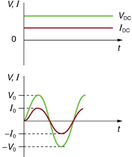
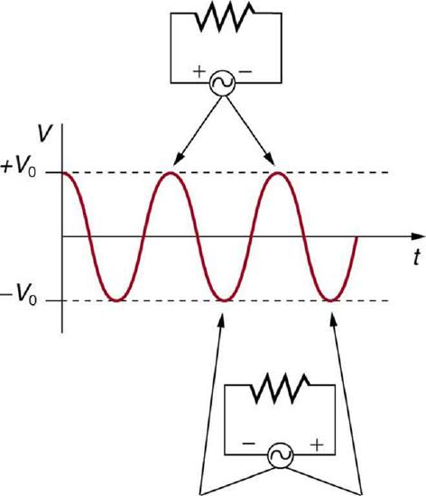
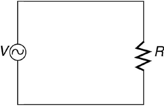
Figure \(\PageIndex{2}\) shows a schematic of a simple circuit with an AC voltage source. The voltage between the terminals fluctuates as shown. For this example, the voltage and current are said to be in phase, as seen in Figure \(\PageIndex{1}\)(b).
Current in the resistor alternates back and forth just like the driving voltage, since \(I=V / R\). If the resistor is a fluorescent light bulb, for example, it brightens and dims 120 times per second as the current repeatedly goes through zero. A 120-Hz flicker is too rapid for your eyes to detect, but if you wave your hand back and forth between your face and a fluorescent light, you will see a stroboscopic effect evidencing AC. The fact that the light output fluctuates means that the power is fluctuating. The power supplied is \(P=I V\).
MAKING CONNECTIONS: TAKE-HOME EXPERIMENT—AC/DC LIGHTS
Wave your hand back and forth between your face and a fluorescent light bulb. Do you observe the same thing with the headlights on your car? Explain what you observe. Warning: Do not look directly at very bright light.
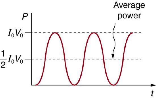
We are most often concerned with average power rather than its fluctuations—that 60-W light bulb in your desk lamp has an average power consumption of 60 W, for example. As illustrated in Figure \(\PageIndex{3}\). One common way to express an average is "root-mean-square," or "rms." For example, rms voltage of an AC voltage source is found by first squaring the voltage ("square"), taking an average of this value over one period of oscillation ("mean"), and taking the square root ("root").
It is standard practice to quote \(I_{\text {rms }}\), \(V_{\text {rms }}\), and \(P_{\text {ave }}\) rather than the peak values. For example, most household electricity is 120 V AC, which means that \(V_{\text {rms }}\) is 120 V. The common 10-A circuit breaker will interrupt a sustained \(I_{\text {rms }}\) greater than 10 A. Your 1.0-kW microwave oven consumes \(P_{\text {ave }}=1.0 \mathrm{~kW}\), and so on. You can think of these rms and average values as the equivalent DC values for a simple resistive circuit.
To summarize, when dealing with AC, Ohm’s law and the equations for power are completely analogous to those for DC, but rms and average values are used for AC. Thus, for AC, Ohm’s law is written
\[I_{\mathrm{rms}}=\frac{V_{\mathrm{rms}}}{R} . \nonumber \]
The various expressions for AC power \(P_{\text {ave }}\) are
\[P_{\text {ave }}=I_{\text {rms }} V_{\text {rms }}, \nonumber \]
\[P_{\mathrm{ave}}=\frac{V_{\mathrm{rms}}^{2}}{R}, \nonumber \]
and
\[P_{\mathrm{ave}}=I_{\mathrm{rms}}^{2} R. \nonumber \]
Why Use AC for Power Distribution?
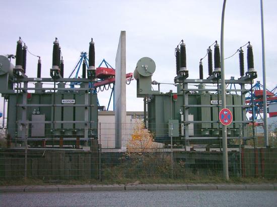
Most large power-distribution systems are AC. Moreover, the power is transmitted at much higher voltages than the 120-V AC (240 V in most parts of the world) we use in homes and on the job. Economies of scale make it cheaper to build a few very large electric power-generation plants than to build numerous small ones. This necessitates sending power long distances, and it is obviously important that energy losses en route be minimized. High voltages can be transmitted with much smaller power losses than low voltages, as we shall show below. (See Figure \(\PageIndex{4}\).) For safety reasons, the voltage at the user is reduced to familiar values. The crucial factor is that AC voltages can be increased and decreased efficiently with transformers (which uses electromagnetic induction to produce time-varying voltages), while it is more difficult to change DC voltages without power losses. So AC is used in most large power distribution systems.
Example \(\PageIndex{1}\): Power Losses Are Less for High-Voltage Transmission
(a) What current is needed to transmit 100 MW of power at 200 kV? (b) What is the power dissipated by the transmission lines if they have a resistance of \(1.00 ~\Omega\)? (c) What percentage of the power is lost in the transmission lines?
- Strategy
-
We are given \(P_{\text {ave }}=100 ~\mathrm{MW}\), \(V_{\mathrm{rms}}=200 ~\mathrm{kV}\), and the resistance of the lines is \(R=1.00 ~\Omega\). Using these givens, we can find the current flowing (from \(P=I V\)) and then the power dissipated in the lines (\(P=I^{2} R\)), and we take the ratio to the total power transmitted.
- Solution
-
a) To find the current, we rearrange the relationship \(P_{\text {ave }}=I_{\text {rms }} V_{\text {rms }}\) and substitute known values. This gives
\[I_{\mathrm{rms}}=\frac{P_{\text {ave }}}{V_{\text {rms }}}=\frac{100 \times 10^{6} \mathrm{~W}}{200 \times 10^{3} \mathrm{~V}}=500 \mathrm{~A}. \nonumber\]
b) Knowing the current and given the resistance of the lines, the power dissipated in them is found from \(P_{\text {ave }}=I_{\text {rms }}^{2} R\). Substituting the known values gives
\[P_{\text {ave }}=I_{\text {rms }}^{2} R=(500 \mathrm{~A})^{2}(1.00 \Omega)=250 \mathrm{~kW}. \nonumber\]
c) The percent loss is the ratio of this lost power to the total or input power, multiplied by 100:
\[\% \text { loss }=\frac{250 \mathrm{~kW}}{100 ~\mathrm{MW}} \times 100=0.250 ~\%. \nonumber\]
Discussion
One-fourth of a percent is an acceptable loss. Note that if 100 MW of power had been transmitted at 25 kV, then a current of 4000 A would have been needed. This would result in a power loss in the lines of 16.0 MW, or 16.0% rather than 0.250%. The lower the voltage, the more current is needed, and the greater the power loss in the fixed-resistance transmission lines. Of course, lower-resistance lines can be built, but this requires larger and more expensive wires. If superconducting lines could be economically produced, there would be no loss in the transmission lines at all. But, as we shall see in a later chapter, there is a limit to current in superconductors, too. In short, high voltages are more economical for transmitting power, and AC voltage is much easier to raise and lower, so that AC is used in most large-scale power distribution systems.
Electrical Safety
Electricity has two hazards. A thermal hazard occurs when there is electrical overheating. A shock hazard occurs when electric current passes through a person. Both hazards have already been discussed. Here we will concentrate on systems and devices that prevent electrical hazards.
Figure 1 shows the schematic for a simple AC circuit with no safety features. This is not how power is distributed in practice. Modern household and industrial wiring requires the three-wire system, shown schematically in Figure 2, which has several safety features. First is the familiar circuit breaker (or fuse) to prevent thermal overload. Second, there is a protective case around the appliance, such as a toaster or refrigerator. The case’s safety feature is that it prevents a person from touching exposed wires and coming into electrical contact with the circuit, helping prevent shocks.
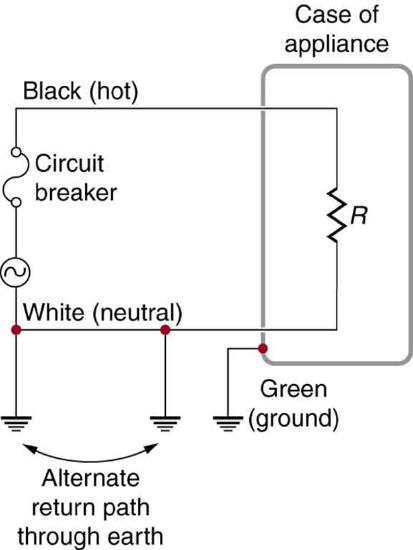
There are three connections to earth or ground (hereafter referred to as “earth/ground”) shown in Figure 2. Recall that an earth/ground connection is a low-resistance path directly to the earth. The two earth/ground connections on the neutral wire force it to be at zero volts relative to the earth, giving the wire its name. This wire is therefore safe to touch even if its insulation, usually white, is missing. The neutral wire is the return path for the current to follow to complete the circuit. Furthermore, the two earth/ground connections supply an alternative path through the earth, a good conductor, to complete the circuit. The earth/ground connection closest to the power source could be at the generating plant, while the other is at the user’s location. The third earth/ground is to the case of the appliance, through the green earth/ground wire, forcing the case, too, to be at zero volts. The live or hot wire (hereafter referred to as “live/hot”) supplies voltage and current to operate the appliance. Figure 3 shows a more pictorial version of how the three-wire system is connected through a three-prong plug to an appliance.

A note on insulation color-coding: Insulating plastic is color-coded to identify live/hot, neutral and ground wires but these codes vary around the world. Live/hot wires may be brown, red, black, blue or grey. Neutral wire may be blue, black or white. Since the same color may be used for live/hot or neutral in different parts of the world, it is essential to determine the color code in your region. The only exception is the earth/ground wire which is often green but may be yellow or just bare wire. Striped coatings are sometimes used for the benefit of those who are colorblind.
The three-wire system replaced the older two-wire system, which lacks an earth/ground wire. Under ordinary circumstances, insulation on the live/hot and neutral wires prevents the case from being directly in the circuit, so that the earth/ground wire may seem like double protection. Grounding the case solves more than one problem, however. The simplest problem is worn insulation on the live/hot wire that allows it to contact the case, as shown in Figure 4 Lacking an earth/ground connection (some people cut the third prong off the plug because they only have outdated two hole receptacles), a severe shock is possible. This is particularly dangerous in the kitchen, where a good connection to earth/ground is available through water on the floor or a water faucet. With the earth/ground connection intact, the circuit breaker will trip, forcing repair of the appliance. Why are some appliances still sold with two-prong plugs? These have nonconducting cases, such as power tools with impact resistant plastic cases, and are called doubly insulated. Modern two-prong plugs can be inserted into the asymmetric standard outlet in only one way, to ensure proper connection of live/hot and neutral wires.

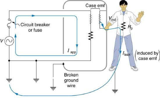
Electromagnetic induction causes a more subtle problem that is solved by grounding the case. The AC current in appliances can induce an emf on the case. If grounded, the case voltage is kept near zero, but if the case is not grounded, a shock can occur as pictured in Figure 5 Current driven by the induced case emf is called a leakage current, although current does not necessarily pass from the resistor to the case.
A ground fault interrupter (GFI) is a safety device found in updated kitchen and bathroom wiring that works based on electromagnetic induction. GFIs compare the currents in the live/hot and neutral wires. When live/hot and neutral currents are not equal, it is almost always because current in the neutral is less than in the live/hot wire. Then some of the current, again called a leakage current, is returning to the voltage source by a path other than through the neutral wire. It is assumed that this path presents a hazard, such as shown in Figure 6. GFIs are usually set to interrupt the circuit if the leakage current is greater than 5 mA, the accepted maximum harmless shock. Even if the leakage current goes safely to earth/ground through an intact earth/ground wire, the GFI will trip, forcing repair of the leakage.

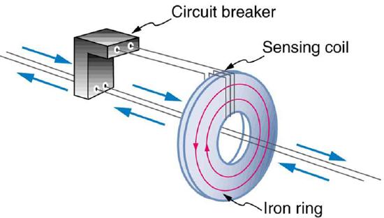
Figure 7 shows how a GFI works. If the currents in the live/hot and neutral wires are equal, then they induce equal and opposite emfs in the coil. If not, then the circuit breaker will trip.
Another induction-based safety device is the isolation transformer, shown in Figure 8. Most isolation transformers have equal input and output voltages. Their function is to put a large resistance between the original voltage source and the device being operated. This prevents a complete circuit between them, even in the circumstance shown. There is a complete circuit through the appliance. But there is not a complete circuit for current to flow through the person in the figure, who is touching only one of the transformer’s output wires, and neither output wire is grounded. The appliance is isolated from the original voltage source by the high resistance of the material between the transformer coils, hence the name isolation transformer. For current to flow through the person, it must pass through the high-resistance material between the coils, through the wire, the person, and back through the earth—a path with such a large resistance that the current is negligible.

The basics of electrical safety presented here help prevent many electrical hazards. Electrical safety can be pursued to greater depths. There are, for example, problems related to different earth/ground connections for appliances in close proximity. Many other examples are found in hospitals. Microshock-sensitive patients, for instance, require special protection. For these people, currents as low as 0.1 mA may cause ventricular fibrillation. The interested reader can use the material presented here as a basis for further study.
Summary
- Ohm’s law for AC is \(I_{\mathrm{rms}}=\frac{V_{\mathrm{rms}}}{R}\).
- Expressions for the average power of an AC circuit are \(P_{\text {ave }}=I_{\text {rms }} V_{\text {rms }}\), \(P_{\text {ave }}=\frac{V_{\text {rms }}{ }^{2}}{R}\), and \(P_{\mathrm{ave}}=I_{\mathrm{rms}}^{2} R\), analogous to the expressions for DC circuits.
- Electrical safety systems and devices are employed to prevent thermal and shock hazards.
- Circuit breakers and fuses interrupt excessive currents to prevent thermal hazards.
- The three-wire system guards against thermal and shock hazards, utilizing live/hot, neutral, and earth/ground wires, and grounding the neutral wire and case of the appliance.
- A ground fault interrupter (GFI) prevents shock by detecting the loss of current to unintentional paths.
- An isolation transformer insulates the device being powered from the original source, also to prevent shock.
- Many of these devices use induction to perform their basic function.
Glossary
direct current
- (DC) the flow of electric charge in only one direction
- alternating current
- (AC) the flow of electric charge that periodically reverses direction
- AC voltage
- voltage that fluctuates sinusoidally with time.
- AC current
- current that fluctuates sinusoidally with time.
- rms
- a type of average taken for a time-varying quantity by squaring it, taking the mean of the square, and then taking the square-root of the mean.
- thermal hazard
- the term for electrical hazards due to overheating
- shock hazard
- the term for electrical hazards due to current passing through a human
- three-wire system
- the wiring system used at present for safety reasons, with live, neutral, and ground wire