1.4: Solving Physics Problems
- Last updated
- Jun 17, 2019
- Save as PDF
- Page ID
- 18092

- Boundless
- Boundless
( \newcommand{\kernel}{\mathrm{null}\,}\)
Dimensional Analysis
Any physical quantity can be expressed as a product of a combination of the basic physical dimensions.
learning objectives
- Calculate the conversion from one kind of dimension to another
Dimensions
The dimension of a physical quantity indicates how it relates to one of the seven basic quantities. These fundamental quantities are:
- [M] Mass
- [L] Length
- [T] Time
- [A] Current
- [K] Temperature
- [mol] Amount of a Substance
- [cd] Luminous Intensity
As you can see, the symbol is enclosed in a pair of square brackets. This is often used to represent the dimension of individual basic quantity. An example of the use of basic dimensions is speed, which has a dimension of 1 in length and -1 in time; [L][T]=[LT−1]. Any physical quantity can be expressed as a product of a combination of the basic physical dimensions.
Dimensional Analysis
Dimensional analysis is the practice of checking relations between physical quantities by identifying their dimensions. The dimension of any physical quantity is the combination of the basic physical dimensions that compose it. Dimensional analysis is based on the fact that physical law must be independent of the units used to measure the physical variables. It can be used to check the plausibility of derived equations, computations and hypotheses.
Derived Dimensions
The dimensions of derived quantities may include few or all dimensions in individual basic quantities. In order to understand the technique to write dimensions of a derived quantity, we consider the case of force. Force is defined as:
F=m⋅aF=[M][a]
The dimension of acceleration, represented as [a], is itself a derived quantity being the ratio of velocity and time. In turn, velocity is also a derived quantity, being ratio of length and time.
F=[M][a]=[M][vT−1]F=[M][LT−1T−1]=[MLT−2]
Dimensional Conversion
In practice, one might need to convert from one kind of dimension to another. For common conversions, you might already know how to convert off the top of your head. But for less common ones, it is helpful to know how to find the conversion factor:
Q=n1u1=n2u2
where n represents the amount per u dimensions. You can then use ratios to figure out the conversion:
n2=u2u1⋅n1
Trigonometry
Trigonometry is central to the use of free body diagrams, which help visually represent difficult physics problems.
learning objectives
- Explain why trigonometry is useful in determining horizontal and vertical components of forces
Trigonometry and Solving Physics Problems
In physics, most problems are solved much more easily when a free body diagram is used. Free body diagrams use geometry and vectors to visually represent the problem. Trigonometry is also used in determining the horizontal and vertical components of forces and objects. Free body diagrams are very helpful in visually identifying which components are unknown and where the moments are applied. They can help analyze a problem, whether it is static or dynamic.
When people draw free body diagrams, often not everything is perfectly parallel and perpendicular. Sometimes people need to analyze the horizontal and vertical components of forces and object orientation. When the force or object is not acting parallel to the x or y axis, people can employ basic trigonometry to use the simplest components of the action to analyze it. Basically, everything should be considered in terms of x and y, which sometimes takes some manipulation.

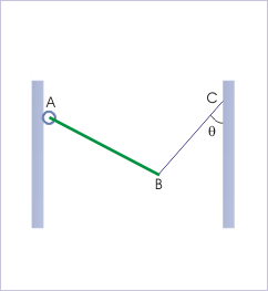
Free Body Diagram: The rod is hinged from a wall and is held with the help of a string.
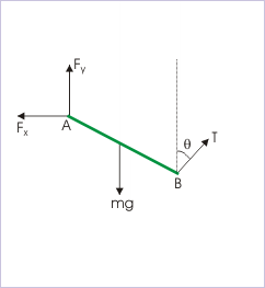
A rod ‘AB’ is hinged at ‘A’ from a wall and is held still with the help of a string, as shown in. This exercise involves drawing the free body diagram. To make the problem easier, the force F will be expressed in terms of its horizontal and vertical components. Removing all other elements from the image helps produce the finished free body diagram.

Free Body Diagram: The free body diagram as a finished product
Given the finished free body diagram, people can use their knowledge of trigonometry and the laws of sine and cosine to mathematically and numerical represent the horizontal and vertical components:
General Problem-Solving Tricks
Free body diagrams use geometry and vectors to visually represent the problem.
learning objectives
- Construct a free-body diagram for a physical scenario
In physics, most problems are solved much more easily when a free body diagram is used. This uses geometry and vectors to visually represent to problem, and trigonometry is also used in determining horizontal and vertical components of forces and objects.
Purpose: Free body diagrams are very helpful in visually identifying which components are unknown, where the moments are applied, and help analyze a problem, whether static or dynamic.
How to Make A Free Body Diagram
To draw a free body diagram, do not worry about drawing it to scale, this will just be what you use to help yourself identify the problems. First you want to model the body, in one of three ways:
- As a particle. This model may be used when any turning effects are zero or have zero interest even though the body itself may be extended. The body may be represented by a small symbolic blob and the diagram reduces to a set of concurrent arrows. A force on a particle is a bound vector.
- rigid extended. Stresses and strains are of no interest but turning effects are. A force arrow should lie along the line of force, but where along the line is irrelevant. A force on an extended rigid body is asliding vector.
- non-rigid extended. The point of application of a force becomes crucial and has to be indicated on the diagram. A force on a non-rigid body is a bound vector. Some engineers use the tail of the arrow to indicate the point of application. Others use the tip.
Do’s and Don’ts
What to include: Since a free body diagram represents the body itself and the external forces on it. So you will want to include the following things in the diagram:
- The body: This is usually sketched in a schematic way depending on the body – particle/extended, rigid/non-rigid – and on what questions are to be answered. Thus if rotation of the body and torque is in consideration, an indication of size and shape of the body is needed.
- The external forces: These are indicated by labelled arrows. In a fully solved problem, a force arrow is capable of indicating the direction, the magnitude the point of application. These forces can be friction, gravity, normal force, drag, tension, etc…
Do not include:
- Do not show bodies other than the body of interest.
- Do not show forces exerted by the body.
- Internal forces acting on various parts of the body by other parts of the body.
- Any velocity or acceleration is left out.
How To Solve Any Physics Problem: Learn five simple steps in five minutes! In this episode we cover the most effective problem-solving method I’ve encountered and call upon some fuzzy friends to help us remember the steps.

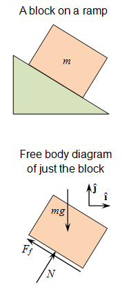
Free Body Diagram: Use this figure to work through the example problem.
Key Points
- Dimensional analysis is the practice of checking relations amount physical quantities by identifying their dimensions.
- It is common to be faced with a problem that uses different dimensions to express the same basic quantity. The following equation can be used to find the conversion factor between the two derived dimensions: n2=u2u1×n1.
- Dimensional analysis can also be used as a simple check to computations, theories and hypotheses.
- It is important to identify the problem and the unknowns and draw them in a free body diagram.
- The laws of cosine and sine can be used to determine the vertical and horizontal components of the different elements of the diagram.
- Free body diagrams use geometry and vectors to visually represent physics problems.
- A free body diagram lets you visually isolate the problem you are trying to solve, and simplify it into simple geometry and trigonometry.
- When drawing these diagrams, it is helpful to only draw the body it self, and the forces acting on it.
- Drawing other objects and internal forces can condense the diagram and cause it to be less helpful.
Key Terms
- dimension: A measure of spatial extent in a particular direction, such as height, width or breadth, or depth.
- trigonometry: The branch of mathematics that deals with the relationships between the sides and the angles of triangles and the calculations based on them, particularly the trigonometric functions.
- static: Fixed in place; having no motion.
- dynamic: Changing; active; in motion.
LICENSES AND ATTRIBUTIONS
CC LICENSED CONTENT, SHARED PREVIOUSLY
- Curation and Revision. Provided by: Boundless.com. License: CC BY-SA: Attribution-ShareAlike
CC LICENSED CONTENT, SPECIFIC ATTRIBUTION
- Dimensional analysis. Provided by: Wikipedia. Located at: http://en.Wikipedia.org/wiki/Dimensional_analysis. License: CC BY-SA: Attribution-ShareAlike
- Sunil Kumar Singh, Dimensional Analysis. September 18, 2013. Provided by: OpenStax CNX. Located at: http://cnx.org/content/m15037/latest/. License: CC BY: Attribution
- dimension. Provided by: Wiktionary. Located at: http://en.wiktionary.org/wiki/dimension. License: CC BY-SA: Attribution-ShareAlike
- Sunil Kumar Singh, Free Body Diagram (Application). September 17, 2013. Provided by: OpenStax CNX. Located at: http://cnx.org/content/m14720/latest/. License: CC BY: Attribution
- trigonometry. Provided by: Wiktionary. Located at: en.wiktionary.org/wiki/trigonometry. License: CC BY-SA: Attribution-ShareAlike
- Sunil Kumar Singh, Free Body Diagram (Application). February 16, 2013. Provided by: OpenStax CNX. Located at: http://cnx.org/content/m14720/latest/. License: CC BY: Attribution
- Sunil Kumar Singh, Free Body Diagram (Application). February 16, 2013. Provided by: OpenStax CNX. Located at: http://cnx.org/content/m14720/latest/. License: CC BY: Attribution
- Free body diagram. Provided by: Wikipedia. Located at: en.Wikipedia.org/wiki/Free_body_diagram. License: CC BY-SA: Attribution-ShareAlike
- dynamic. Provided by: Wiktionary. Located at: en.wiktionary.org/wiki/dynamic. License: CC BY-SA: Attribution-ShareAlike
- static. Provided by: Wiktionary. Located at: en.wiktionary.org/wiki/static. License: CC BY-SA: Attribution-ShareAlike
- Sunil Kumar Singh, Free Body Diagram (Application). February 16, 2013. Provided by: OpenStax CNX. Located at: http://cnx.org/content/m14720/latest/. License: CC BY: Attribution
- Sunil Kumar Singh, Free Body Diagram (Application). February 16, 2013. Provided by: OpenStax CNX. Located at: http://cnx.org/content/m14720/latest/. License: CC BY: Attribution
- Free Body Diagram. Provided by: Wikipedia. Located at: en.Wikipedia.org/wiki/File:Free_Body_Diagram.png. License: CC BY-SA: Attribution-ShareAlike
- How To Solve Any Physics Problem. Located at: http://www.youtube.com/watch?v=YocWuzi4JhY. License: Public Domain: No Known Copyright. License Terms: Standard YouTube license


