
21.5: Transmission Lines as Two-Port Devices


- Last updated
- Aug 26, 2024
- Save as PDF

( \newcommand{\kernel}{\mathrm{null}\,}\)
Figure 21.5.1 shows common ways to represent transmission lines in circuit diagrams. In each case, the source is represented using a Thévenin equivalent circuit consisting of a voltage source VS in series with an impedance ZS.1 In transmission line analysis, the source may also be referred to as the generator. The termination on the receiving end of the transmission line is represented, without loss of generality, as an impedance ZL. This termination is often referred to as the load, although in practice it can be any circuit that exhibits an input impedance of ZL.
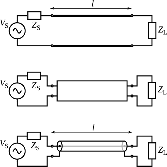 Figure 21.5.1: Symbols representing transmission lines: Top: As a generic two-conductor direct connection. Middle: As a generic two-port “black box.” Bottom: As a coaxial cable. © CC BY SA 3.0 Unported (modified)
The two-port representation of a transmission line is completely described by its length l along with some combination of the following parameters:
- Phase propagation constant β, having units of rad/m. This parameter also represents the wavelength in the line through the relationship λ=2π/β. (See Sections 1.3 and 3.8 for details.)
- Attenuation constant α, having units of 1/m. This parameter quantifies the effect of loss in the line. (See Section 3.8 for details.)
- Characteristic impedance Z0, having units of Ω. This is the ratio of potential (“voltage”) to current when the line is perfectly impedance-matched at both ends. (See Section 3.7 for details.)
These parameters depend on the materials and geometry of the line.
Note that a transmission line is typically not transparent to the source and load. In particular, the load impedance may be ZL, but the impedance presented to the source may or may not be equal to ZL. (See Section 3.15 for more on this concept.) Similarly, the source impedance may be ZS, but the impedance presented to the load may or may not be equal to ZS. The effect of the transmission line on the source and load impedances will depend on the parameters identified above.
- For a refresher on this concept, see “Additional Reading” at the end of this section.↩