19.3: Resistance and Resistors
- Last updated
- Jan 15, 2019
- Save as PDF
- Page ID
- 17025

- Boundless
- Boundless
( \newcommand{\kernel}{\mathrm{null}\,}\)
- Contrast shape of current-voltage plots for ohmic and non-ohmic circuits
Ohm’s Law
What drives current? We can think of various devices—such as batteries, generators, wall outlets, and so on—which are necessary to maintain a current. All such devices create a potential difference and are loosely referred to as voltage sources. When a voltage source is connected to a conductor, it applies a potential difference V that creates an electric field. The electric field, in turn, exerts force on charges, causing current. The current that flows through most substances is directly proportional to the voltage V applied to it. The German physicist Georg Simon Ohm (1787-1854) was the first to experimentally demonstrate that the current in a metal wire is directly proportional to the voltage applied:\ mathrmI∝V.
This important relationship is known as Ohm’s law. It can be viewed as a cause-and-effect relationship, with voltage the cause and current the effect. This is an empirical law like that for friction—an experimentally observed phenomenon. Such a linear relationship doesn’t always occur. Recall that while voltage drives current, resistance impedes it. Collisions of moving charges with atoms and molecules in a substance transfer energy to the substance and limit current. The current is therefore inversely proportional to the resistance: I∝1R.
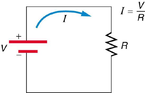
Simple Circuit: A simple electric circuit in which a closed path for current to flow is supplied by conductors (usually metal wires) connecting a load to the terminals of a battery, represented by the red parallel lines. The zigzag symbol represents the single resistor and includes any resistance in the connections to the voltage source.
The unit for resistance is the ohm where 1Ω = 1 V/A. We can combine the two relations above to obtain I = V/R. This relationship is also called Ohm’s law. In this form Ohm’s law really defines resistance for certain materials. Ohm’s law (like Hooke’s law) is not universally valid. The many substances for which Ohm’s law holds are called ohmic. These include good conductors like copper and aluminum, and some poor conductors under certain circumstances. Ohmic materials have a resistance R that is independent of voltage V and current I. An object that has simple resistance is called a resistor, even if its resistance is small.
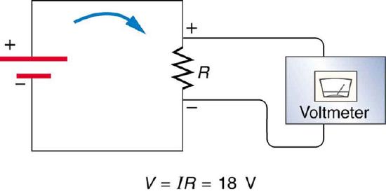
Voltage Drop: The voltage drop across a resistor in a simple circuit equals the voltage output of the battery.
Additional insight is gained by solving I=V/R for V, yielding V=IR. This expression for V can be interpreted as the voltage drop across a resistor produced by the flow of current I. The phrase IR drop is often used for this voltage. If voltage is measured at various points in a circuit, it will be seen to increase at the voltage source and decrease at the resistor. Voltage is similar to fluid pressure. The voltage source is like a pump, creating a pressure difference, causing current—the flow of charge. The resistor is like a pipe that reduces pressure and limits flow because of its resistance. Conservation of energy has important consequences here. The voltage source supplies energy (causing an electric field and a current), and the resistor converts it to another form (such as thermal energy). In a simple circuit (one with a single simple resistor), the voltage supplied by the source equals the voltage drop across the resistor, since E=qΔV, and the same q flows through each. Thus, the energy supplied by the voltage source and the energy converted by the resistor are equal.
In a true ohmic device, the same value of resistance will be calculated from R = V/I regardless of the value of the applied voltage V. That is, the ratio of V/I is constant, and when current is plotted as a function of voltage the curve is linear (a straight line). If voltage is forced to some value V, then that voltage V divided by measured current I will equal R. Or if the current is forced to some value I, then the measured voltage V divided by that current I is also R. We visualize the plot of I versus V as a straight line. There are, however, components of electrical circuits which do not obey Ohm’s law; that is, their relationship between current and voltage (their I–V curve) is nonlinear (or non-ohmic). An example is the p-n junction diode.

Current-Voltage Curves: The I–V curves of four devices: two resistors, a diode, and a battery. The two resistors follow Ohm’s law: The plot is a straight line through the origin. The other two devices do not follow Ohm’s law.
Ohm’s Law: A brief overview of Ohm’s Law.
Temperature and Superconductivity
Superconductivity is a phenomenon of zero electrical resistance and expulsion of magnetic fields in certain materials below a critical temp.
learning objectives
- Describe behaviors of a superconductor below a critical temperature and in a weak external magnetic field
Superconductivity is a phenomenon of exactly zero electrical resistance and expulsion of magnetic fields occurring in certain materials when cooled below a characteristic critical temperature. It was discovered by Heike Kamerlingh Onnes (shown in ) on April 8, 1911 in Leiden.
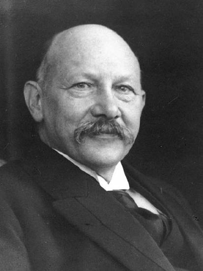
Heike Kamerlingh Onnes: Heike Kamerlingh Onnes (1853-1926).
Most of the physical properties of superconductors vary from material to material, such as the heat capacity and the critical temperature, critical field, and critical current density at which superconductivity is destroyed. On the other hand, there is a class of properties independent of the underlying material. For instance, all superconductors have exactly zero resistivity to low applied currents when there is no magnetic field present or if the applied field does not exceed a critical value. The existence of these “universal” properties implies that superconductivity is a thermodynamic phase, and thus possesses certain distinguishing properties that are largely independent of microscopic details.
In superconducting materials, the characteristics of superconductivity appear when the temperature T is lowered below a critical temperature Tc. The onset of superconductivity is accompanied by abrupt changes in various physical properties—the hallmark of a phase transition. For example, the electronic heat capacity is proportional to the temperature in the normal (non-superconducting) regime. At the superconducting transition, it suffers a discontinuous jump and thereafter ceases to be linear, as illustrated in.
When a superconductor is placed in a weak external magnetic field H, and cooled below its transition temperature, the magnetic field is ejected. The Meissner effect does not cause the field to be completely ejected. Rather, the field penetrates the superconductor to a very small distance (characterized by a parameter λ), called the London penetration depth. It decays exponentially to zero within the bulk of the material. The Meissner effect is a defining characteristic of superconductivity. For most superconductors, the London penetration depth is on the order of 100 nm.
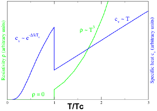
Superconducting phase transition: Behavior of heat capacity (cv, blue) and resistivity (ρ, green) at the superconducting phase transition.
Superconductors are also able to maintain a current with no applied voltage whatsoever—a property exploited in superconducting electromagnets such as those found in MRI machines. Experiments have demonstrated that currents in superconducting coils can persist for years without any measurable degradation. Experimental evidence points to a current lifetime of at least 100,000 years. Theoretical estimates for the lifetime of a persistent current can exceed the estimated lifetime of the universe, depending on the wire geometry and the temperature.
The value of this critical temperature varies from material to material. Usually, conventional superconductors have critical temperatures ranging from around 20 K to less than 1 K. Solid mercury, for example, has a critical temperature of 4.2 K. As of 2009, the highest critical temperature found for a conventional superconductor is 39 K for magnesium diboride (MgB2), although this material’s exotic properties cause some doubt about accurately classifying it as a “conventional” superconductor. High-temperature superconductors can have much higher critical temperatures. For example, YBa2Cu3O7, one of the first cuprate superconductors to be discovered, has a critical temperature of 92 K; mercury-based cuprates have been found with critical temperatures in excess of 130 K. It is of note that the chemical composition and crystal structure of superconducting materials can be quite complex, as seen in.
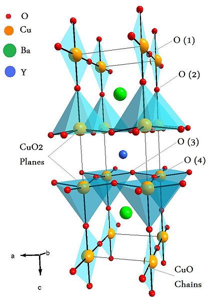
Unit Cell of YBaCuO superconductor: Unit Cell of YBaCuO superconductor. Atoms are indicated with different colors.
Resistance and Resistivity
Resistance and resistivity describe the extent to which an object or material impedes the flow of electric current.
learning objectives
- Identify properties of the material that are described by the resistance and resistivity
Resistance and Resistivity
Resistance is the electric property that impedes a current. A current flowing through a wire (or resistor) is like water flowing through a pipe, and the voltage drop across the wire is like the pressure drop which pushes water through the pipe. Resistance is proportional to how much pressure is required to achieve a given flow, while conductance is proportional to how much flow occurs for a given pressure. Conductance and resistance are reciprocals. The resistance of an object depends on its shape and the material of which it is composed. The cylindrical resistor is easy to analyze, and by so doing we can gain insight into the resistance of more complicated shapes. As you might expect, the cylinder’s electric resistance R is directly proportional to its length L, similar to the resistance of a pipe to fluid flow. The longer the cylinder, the more collisions charges will make with its atoms. The greater the diameter of the cylinder, the more current it can carry (again, similar to the flow of fluid through a pipe). In fact, R is inversely proportional to the cylinder’s cross-sectional area A.
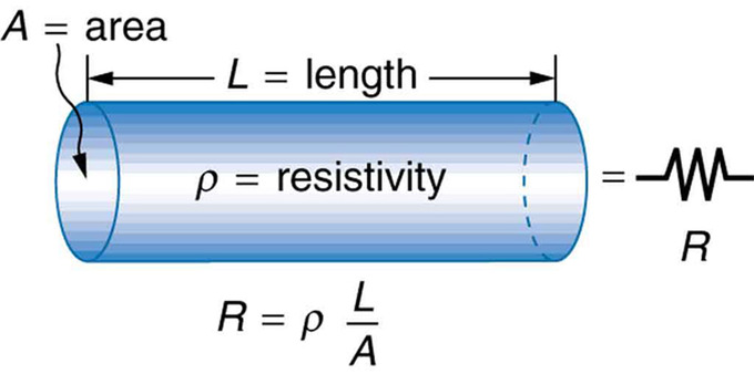
Cylindrical Resistor: A uniform cylinder of length L and cross-sectional area A. Its resistance to the flow of current is similar to the resistance posed by a pipe to fluid flow. The longer the cylinder, the greater its resistance. The larger its cross-sectional area A, the smaller its resistance.
As mentioned, for a given shape, the resistance depends on the material of which the object is composed. Different materials offer different resistance to the flow of charge. We define the resistivity ρ of a substance so that theresistanceR of an object is directly proportional to ρ. Resistivity ρ is an intrinsic property of a material, independent of its shape or size. In contrast, the resistance R is an extrinsic property that does depend on the size an shape of the resistor. (A similar intrinsic/extrinsic relation exists between heat capacity C and the specific heat c). Recall that an object whose resistance is proportional to the voltage and current is known as a resistor.

Typical Resistor: A typical axial-lead resistor.
What determines resistivity? The resistivity of different materials varies by an enormous amount. For example, the conductivity of teflon is about 1030 times lower than the conductivity of copper. Why is there such a difference? Loosely speaking, a metal has large numbers of “delocalized” electrons that are not stuck in any one place, but free to move across large distances, whereas in an insulator (like teflon), each electron is tightly bound to a single atom, and a great force is required to pull it away. Likewise, resistors range over many orders of magnitude. Some ceramic insulators, such as those used to support power lines, have resistances of 1012 Ω or more. A dry person may have a hand-to-foot resistance of 105 Ω, whereas the resistance of the human heart is about 103 Ω. A meter-long piece of large-diameter copper wire may have a resistance of 10−5 Ω, and superconductors have no resistance at all (they are non-ohmic). The potential difference (voltage) seen across the network is the sum of those voltages, thus the total resistance (the series equivalent resistance) can be found as the sum of those resistances:
Req=R1+R2+⋯+RN
As a special case, the resistance of N resistors connected in series, each of the same resistance R, is given by NR.Resistors in a parallel configuration are each subject to the same potential difference (voltage), however the currents through them add. Thus the equivalent resistance (Req) of the network can be computed:
1Req=1R1+1R2+⋯+1RN
The parallel equivalent resistance can be represented in equations by two vertical lines “||” (as in geometry) as a simplified notation. Occasionally two slashes “//” are used instead of “||”, in case the keyboard or font lacks the vertical line symbol. For the case of two resistors in parallel, this can be calculated using:
Req=R1‖R2=R1R2R1+R2
As a special case, the resistance of N resistors connected in parallel, each of the same resistance R, is given by R/N. A resistor network that is a combination of parallel and series connections can be broken up into smaller parts that are either one or the other, such as is shown in.

Resistor Network: In this combination circuit, the circuit can be broken up into a series component and a parallel component.
However, some complex networks of resistors cannot be resolved in this manner. These require a more sophisticated circuit analysis. One practical application of these relationships is that a non-standard value of resistance can generally be synthesized by connecting a number of standard values in series or parallel. This can also be used to obtain a resistance with a higher power rating than that of the individual resistors used. In the special case of N identical resistors all connected in series or all connected in parallel, the power rating of the individual resistors is thereby multiplied by N.
Resistance, Resistors, and Resistivity: A brief overview of resistance, resistors, and resistivity.
Dependence of Resistance on Temperature
Resistivity and resistance depend on temperature with the dependence being linear for small temperature changes and nonlinear for large.
learning objectives
- Compare temperature dependence of resistivity and resistance for large and small temperature changes
The resistivity of all materials depends on temperature. Some materials can become superconductors (zero resistivity) at very low temperatures (see ). Conversely, the resistivity of conductors increases with increasing temperature. Since the atoms vibrate more rapidly and over larger distances at higher temperatures, the electrons moving through a metal, for example, create more collisions, effectively making the resistivity higher. Over relatively small temperature changes (about 100ºC or less), resistivity ρ varies with temperature change ΔT as expressed in the following equation:
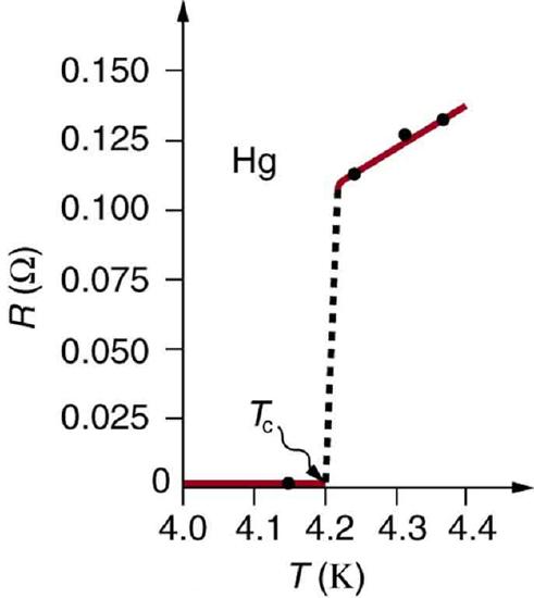
Resistance of a sample of mercury: The resistance of a sample of mercury is zero at very low temperatures—it is a superconductor up to about 4.2 K. Above that critical temperature, its resistance makes a sudden jump and then increases nearly linearly with temperature.
p=p0(1+αΔT)
where ρ0 is the original resistivity and α is the temperature coefficient of resistivity. For larger temperature changes, α may vary, or a nonlinear equation may be needed to find ρ. For this reason it is usual to specify a suffix for the temperature at which the substance was measured (such as α15) and the relationship only holds in a range of temperatures around the reference. Note that α is positive for metals, meaning their resistivity increases with temperature. The temperature coefficient is typically +3×10⁻³ K−1 to +6×10⁻³ K−1 for metals near room temperature. Some alloys have been developed specifically to have a small temperature dependence. Manganin (made of copper, manganese and nickel), for example, has α close to zero, so its resistivity varies only slightly with temperature. This is useful for making a temperature-independent resistance standard, for example.
Note also that α is negative for semiconductors, meaning that their resistivity decreases with increasing temperature. They become better conductors at higher temperature because increased thermal agitation increases the number of free charges available to carry current. This property of decreasing ρ with temperature is also related to the type and amount of impurities present in the semiconductors.
The resistance of an object also depends on temperature, since R0 is directly proportional to ρ. For a cylinder we know R=ρL/A, so if L and A do not change greatly with temperature, R will have the same temperature dependence as ρ. (Examination of the coefficients of linear expansion shows them to be about two orders of magnitude less than typical temperature coefficients of resistivity, and so the effect of temperature on L and A is about two orders of magnitude less than on ρ. ) Thus,
R=R0(1+αΔT)
is the temperature dependence of the resistance of an object, where R0 is the original resistance and R is the resistance after a temperature change T. Numerous thermometers are based on the effect of temperature on resistance (see ). One of the most common is the thermistor, a semiconductor crystal with a strong temperature dependence, the resistance of which is measured to obtain its temperature. The device is small so it quickly comes into thermal equilibrium with the part of a person it touches.
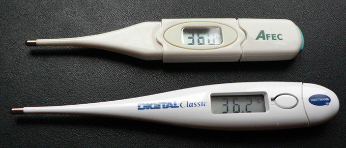
Thermometers: These familiar thermometers are based on the automated measurement of a thermistor’s temperature-dependent resistance.
Key Points
- Voltage drives current while resistance impedes it.
- Ohm ‘s Law refers to the proportion relation between voltage and current. It also applies to the specific equation V=IR, which is valid when considering circuits that contain simple resistors (whose resistance is independent of voltage and current).
- Circuits or components that obey the relation V=IR are known as ohmic and have current-voltage plots that are linear and pass through the origin.
- There are components and circuits that are non-ohmic; their I-V plots are not linear and/or don’t pass through the origin.
- Superconductivity is a Superconductivity is a thermodynamic phase and possesses certain distinguishing properties which are largely independent of microscopic details.
- In superconducting materials, the characteristics of superconductivity appear when the temperature is lowered below a critical temperature. The onset of superconductivity is accompanied by abrupt changes in various physical properties.
- When a superconductor is placed in a weak external magnetic field H, and cooled below its transition temperature, the magnetic field is ejected.
- Superconductors are able to maintain a current with no applied voltage.
- The resistance of an object (i.e., a resistor ) depends on its shape and the material of which it is composed.
- Resistivity ρ is an intrinsic property of a material and directly proportional to the total resistance R, an extrinsic quantity that depends on the length and cross-sectional area of a resistor.
- The resistivity of different materials varies by an enormous amount. Likewise, resistors range over many orders of magnitude.
- Resistors are arranged in series or parallel configurations. The equivalent resistance of a network of resistors in series is the sum of all the resistance. The inverse of the equivalent resistance of a network of resistors in parallel is the sum of the inverse of the resistance of each resistor.
- Over temperature changes of 100ºC or less, resistivity (ρ) varies with temperature change ΔT as: p=p0(1+αΔT)p=p0(1+αΔT) where ρ0 is the original resistivity and α is the temperature coefficient of resistivity.
- For large temperature changes, nonlinear variation of resistivity with temperature is observed.
- The resistance of an object demonstrates similar temperature dependence as resistivity since resistance is directly proportional to resistivity.
Key Terms
- simple circuit: A circuit with a single voltage source and a single resistor.
- ohmic: That which obeys Ohm’s law.
- high-temperature superconductors: Materials that behave as superconductors at unusually high temperatures (above about 30 K).
- critical temperature: In superconducting materials, the characteristics of superconductivity appears at (and continues below) this temperature.
- superconductivity: The property of a material whereby it has no resistance to the flow of an electric current.
- series equivalent resistance: The resistance of a network of resistors arranged such that the voltage across the network is the sum of the voltage across each resistor. In this case, the equivalent resistance is the sum of the resistance of all the resistors in the network.
- parallel equivalent resistance: the resistance of a network such that each resistor is subject to the same potential difference (voltage), so that the currents through them add. In this case the inverse of the equivalent resistance is equal to the sum of the inverse resistance of all the resistors in the network.
- resistivity: In general, the resistance to electric current of a material; in particular, the degree to which a material resists the flow of electricity.
- temperature coefficient of resistivity: An empirical quantity, denoted by α, which describes the change in resistance or resistivity of a material with temperature.
- semiconductor: A substance with electrical properties intermediate between a good conductor and a good insulator.
LICENSES AND ATTRIBUTIONS
CC LICENSED CONTENT, SHARED PREVIOUSLY
- Curation and Revision. Provided by: Boundless.com. License: CC BY-SA: Attribution-ShareAlike
CC LICENSED CONTENT, SPECIFIC ATTRIBUTION
- OpenStax College, College Physics. September 18, 2013. Provided by: OpenStax CNX. Located at: http://cnx.org/content/m42344/latest/?collection=col11406/1.7. License: CC BY: Attribution
- Ohm's law. Provided by: Wikipedia. Located at: en.Wikipedia.org/wiki/Ohm's_law. License: CC BY-SA: Attribution-ShareAlike
- ohmic. Provided by: Wiktionary. Located at: en.wiktionary.org/wiki/ohmic. License: CC BY-SA: Attribution-ShareAlike
- Boundless. Provided by: Boundless Learning. Located at: www.boundless.com//physics/definition/simple-circuit. License: CC BY-SA: Attribution-ShareAlike
- OpenStax College, College Physics. October 22, 2012. Provided by: OpenStax CNX. Located at: http://cnx.org/content/m42344/latest/?collection=col11406/1.7. License: CC BY: Attribution
- Ohm's Law. Located at: http://www.youtube.com/watch?v=uLU4LtG0_hc. License: Public Domain: No Known Copyright. License Terms: Standard YouTube license
- Ohm's law. Provided by: Wikipedia. Located at: en.Wikipedia.org/wiki/Ohm's_law. License: Public Domain: No Known Copyright
- OpenStax College, College Physics. October 22, 2012. Provided by: OpenStax CNX. Located at: http://cnx.org/content/m42344/latest/?collection=col11406/1.7. License: CC BY: Attribution
- Superconductors. Provided by: Wikipedia. Located at: en.Wikipedia.org/wiki/Superconductors. License: CC BY-SA: Attribution-ShareAlike
- superconductivity. Provided by: Wiktionary. Located at: en.wiktionary.org/wiki/superconductivity. License: CC BY-SA: Attribution-ShareAlike
- Boundless. Provided by: Boundless Learning. Located at: www.boundless.com//chemistry/definition/critical-temperature. License: CC BY-SA: Attribution-ShareAlike
- high-temperature superconductors. Provided by: Wikipedia. Located at: en.Wikipedia.org/wiki/high-temperature%20superconductors. License: CC BY-SA: Attribution-ShareAlike
- OpenStax College, College Physics. October 22, 2012. Provided by: OpenStax CNX. Located at: http://cnx.org/content/m42344/latest/?collection=col11406/1.7. License: CC BY: Attribution
- Ohm's Law. Located at: http://www.youtube.com/watch?v=uLU4LtG0_hc. License: Public Domain: No Known Copyright. License Terms: Standard YouTube license
- Ohm's law. Provided by: Wikipedia. Located at: en.Wikipedia.org/wiki/Ohm's_law. License: Public Domain: No Known Copyright
- OpenStax College, College Physics. October 22, 2012. Provided by: OpenStax CNX. Located at: http://cnx.org/content/m42344/latest/?collection=col11406/1.7. License: CC BY: Attribution
- Provided by: Wikimedia. Located at: http://upload.wikimedia.org/Wikipedia/commons/thumb/9/94/Kamerlingh_portret.jpg/450px-Kamerlingh_portret.jpg. License: CC BY-SA: Attribution-ShareAlike
- Provided by: Wikimedia. Located at: http://upload.wikimedia.org/Wikipedia/commons/thumb/0/06/Ybco.jpg/424px-Ybco.jpg. License: CC BY-SA: Attribution-ShareAlike
- Superconductors. Provided by: Wikipedia. Located at: en.Wikipedia.org/wiki/Superconductors. License: Public Domain: No Known Copyright
- OpenStax College, College Physics. September 18, 2013. Provided by: OpenStax CNX. Located at: http://cnx.org/content/m42344/latest/?collection=col11406/1.7. License: CC BY: Attribution
- Electrical resistance. Provided by: Wikipedia. Located at: en.Wikipedia.org/wiki/Electrical_resistance. License: CC BY-SA: Attribution-ShareAlike
- Ohm's law. Provided by: Wikipedia. Located at: en.Wikipedia.org/wiki/Ohm's_law. License: CC BY-SA: Attribution-ShareAlike
- OpenStax College, College Physics. September 18, 2013. Provided by: OpenStax CNX. Located at: http://cnx.org/content/m42346/latest/?collection=col11406/1.7. License: CC BY: Attribution
- Resistors. Provided by: Wikipedia. Located at: en.Wikipedia.org/wiki/Resistors. License: CC BY-SA: Attribution-ShareAlike
- Boundless. Provided by: Boundless Learning. Located at: www.boundless.com//physics/definition/parallel-equivalent-resistance. License: CC BY-SA: Attribution-ShareAlike
- resistivity. Provided by: Wiktionary. Located at: en.wiktionary.org/wiki/resistivity. License: CC BY-SA: Attribution-ShareAlike
- Boundless. Provided by: Boundless Learning. Located at: www.boundless.com//physics/definition/series-equivalent-resistance. License: CC BY-SA: Attribution-ShareAlike
- OpenStax College, College Physics. October 22, 2012. Provided by: OpenStax CNX. Located at: http://cnx.org/content/m42344/latest/?collection=col11406/1.7. License: CC BY: Attribution
- Ohm's Law. Located at: http://www.youtube.com/watch?v=uLU4LtG0_hc. License: Public Domain: No Known Copyright. License Terms: Standard YouTube license
- Ohm's law. Provided by: Wikipedia. Located at: en.Wikipedia.org/wiki/Ohm's_law. License: Public Domain: No Known Copyright
- OpenStax College, College Physics. October 22, 2012. Provided by: OpenStax CNX. Located at: http://cnx.org/content/m42344/latest/?collection=col11406/1.7. License: CC BY: Attribution
- Provided by: Wikimedia. Located at: http://upload.wikimedia.org/Wikipedia/commons/thumb/9/94/Kamerlingh_portret.jpg/450px-Kamerlingh_portret.jpg. License: CC BY-SA: Attribution-ShareAlike
- Provided by: Wikimedia. Located at: http://upload.wikimedia.org/Wikipedia/commons/thumb/0/06/Ybco.jpg/424px-Ybco.jpg. License: CC BY-SA: Attribution-ShareAlike
- Superconductors. Provided by: Wikipedia. Located at: en.Wikipedia.org/wiki/Superconductors. License: Public Domain: No Known Copyright
- Resistors. Provided by: Wikipedia. Located at: en.Wikipedia.org/wiki/Resistors. License: Public Domain: No Known Copyright
- OpenStax College, College Physics. October 22, 2012. Provided by: OpenStax CNX. Located at: http://cnx.org/content/m42346/latest/?collection=col11406/1.7. License: CC BY: Attribution
- Resistance, Resistors, and Resistivity. Located at: http://www.youtube.com/watch?v=YXYpR5RmTBk. License: Public Domain: No Known Copyright. License Terms: Standard YouTube license
- Resistors. Provided by: Wikipedia. Located at: en.Wikipedia.org/wiki/Resistors. License: Public Domain: No Known Copyright
- OpenStax College, College Physics. September 17, 2013. Provided by: OpenStax CNX. Located at: http://cnx.org/content/m42346/latest/?collection=col11406/1.7. License: CC BY: Attribution
- Electrical resistance. Provided by: Wikipedia. Located at: en.Wikipedia.org/wiki/Electrical_resistance. License: CC BY-SA: Attribution-ShareAlike
- Electrical resistivity and conductivity. Provided by: Wikipedia. Located at: en.Wikipedia.org/wiki/Electrical_resistivity_and_conductivity%23Temperature_dependence. License: CC BY-SA: Attribution-ShareAlike
- semiconductor. Provided by: Wiktionary. Located at: en.wiktionary.org/wiki/semiconductor. License: CC BY-SA: Attribution-ShareAlike
- resistivity. Provided by: Wiktionary. Located at: en.wiktionary.org/wiki/resistivity. License: CC BY-SA: Attribution-ShareAlike
- Boundless. Provided by: Boundless Learning. Located at: www.boundless.com//physics/definition/temperature-coefficient-of-resistivity. License: CC BY-SA: Attribution-ShareAlike
- OpenStax College, College Physics. October 22, 2012. Provided by: OpenStax CNX. Located at: http://cnx.org/content/m42344/latest/?collection=col11406/1.7. License: CC BY: Attribution
- Ohm's Law. Located at: http://www.youtube.com/watch?v=uLU4LtG0_hc. License: Public Domain: No Known Copyright. License Terms: Standard YouTube license
- Ohm's law. Provided by: Wikipedia. Located at: en.Wikipedia.org/wiki/Ohm's_law. License: Public Domain: No Known Copyright
- OpenStax College, College Physics. October 22, 2012. Provided by: OpenStax CNX. Located at: http://cnx.org/content/m42344/latest/?collection=col11406/1.7. License: CC BY: Attribution
- Provided by: Wikimedia. Located at: http://upload.wikimedia.org/Wikipedia/commons/thumb/9/94/Kamerlingh_portret.jpg/450px-Kamerlingh_portret.jpg. License: CC BY-SA: Attribution-ShareAlike
- Provided by: Wikimedia. Located at: http://upload.wikimedia.org/Wikipedia/commons/thumb/0/06/Ybco.jpg/424px-Ybco.jpg. License: CC BY-SA: Attribution-ShareAlike
- Superconductors. Provided by: Wikipedia. Located at: en.Wikipedia.org/wiki/Superconductors. License: Public Domain: No Known Copyright
- Resistors. Provided by: Wikipedia. Located at: en.Wikipedia.org/wiki/Resistors. License: Public Domain: No Known Copyright
- OpenStax College, College Physics. October 22, 2012. Provided by: OpenStax CNX. Located at: http://cnx.org/content/m42346/latest/?collection=col11406/1.7. License: CC BY: Attribution
- Resistance, Resistors, and Resistivity. Located at: http://www.youtube.com/watch?v=YXYpR5RmTBk. License: Public Domain: No Known Copyright. License Terms: Standard YouTube license
- Resistors. Provided by: Wikipedia. Located at: http://en.Wikipedia.org/wiki/Resistors. License: Public Domain: No Known Copyright
- OpenStax College, College Physics. October 22, 2012. Provided by: OpenStax CNX. Located at: http://cnx.org/content/m42346/latest/?collection=col11406/1.7. License: CC BY: Attribution
- OpenStax College, College Physics. October 22, 2012. Provided by: OpenStax CNX. Located at: http://cnx.org/content/m42346/latest/?collection=col11406/1.7. License: CC BY: Attribution


