4.4: Mirrors
- Last updated
- Jan 15, 2019
- Save as PDF
- Page ID
- 17113
( \newcommand{\kernel}{\mathrm{null}\,}\)
learning objectives
- Describe interaction of the light with a mirror surface
Plane Mirrors and Reflection
A mirror is a reflective surface that does not allow the passage of light and instead bounces it off, thus producing an image. The most common mirrors are flat and called plane mirrors. These mirrors are made by putting a thin layer of silver nitrate or aluminium behind a flat piece of glass.
When you place an object in front of a mirror, you see an image of the same object in the mirror. The object is the source of the incident rays, and the image is formed by the reflected rays. An image formed by reflection may be real or virtual. A “real” image occurs when light rays actually intersect at the image, and become inverted, or turned upside down. A “virtual” image occurs when light rays do not actually meet at the image. Instead, you “see” the image because your eye projects light rays backward. You are fooled into seeing an image! A virtual image is right side up (upright).
In flat, or plane mirrors, the image is a virtual image, and is the same distance behind the mirror as the object is in front of the mirror. The image is also the same size as the object. These images are also parity inverted, which means they have a left-right inversion.
Ray Diagrams
The way that we can predict how a reflection will look is by drawing a ray diagram. These diagrams can be used to find the position and size of the image and whether that image is real or virtual. These are the steps you follow to draw a ray diagram:
- Draw the plane mirror as a straight line on a principal axis. The principal axis is an imaginary line that is drawn perpendicular to the mirror.
- Draw the object as an arrow in front of the mirror.
- Draw the image of the object, by using the principle that the image is placed at the same distance behind the mirror that the object is in front of the mirror. The image size is also the same as the object size. shows these first three steps.
- Place a dot at the point the eye is located.
- Pick one point on the image and draw the reflected ray that travels to the eye as it sees this point. Remember to add an arrowhead.
- Draw the incident ray for light traveling from the corresponding point on the object to the mirror, such that the law of reflection is obeyed.
- Continue for other extreme points on the object (i.e. the tip and base of the arrow). A completed ray diagram is shown in
The angle in which a light ray hits the mirror is the same angle in which it will be reflected back. If, for example, a light ray leaves the top of an object travelling parallel to the principal axis, it will hit the mirror at a 0 degree angle, and be reflected back at 0 degrees. When this happens, we say the ray hit the mirror normally. If the light ray hit the object at a 30 degree angle, it will be reflected back at a 30 degree angle.
Image Formation by Spherical Mirrors: Reflection and Sign Conventions
A mirror is a reflective surface that light does not pass through, made by a layer of silver nitrate or aluminium behind piece of glass.
learning objectives
- Distinguish properties of the concave and the convex mirrors
Overview
A mirror is a reflective surface that light does not pass through, but bounces off of and this produces an image. Mirrors are made by putting a thin layer of silver nitrate or aluminium behind a flat piece of glass.
When you place an object in front of a mirror, you see the same object in the mirror. This image that appears to be behind the mirror is called the image. The object is the source of the incident rays, and the image is formed by the reflected rays. An image formed by reflection may be real or virtual. A real image occurs when light rays actually intersect at the image, and is inverted, or upside down. A virtual image occurs when light rays do not actually meet at the image. Instead, you “see” the image because your eye projects light rays backward. A virtual image is right side up (upright).
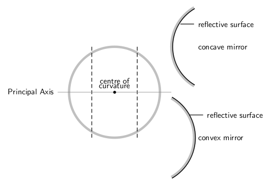
This section will cover spherical mirrors. Spherical mirrors can be either concave or convex. The center of curvature is the point at the center of the sphere and describes how big the sphere is. These concepts are shown in.

Spherical Mirrors: This figure shows the difference between a concave and convex mirror.
Concave Mirrors
In a concave mirror, the principal axis is a line that is perpendicular to the center of the mirror. The easiest way to visualize what a image will look like in this type of mirror is a ray diagram. Before that can be done, the focal point must first be defined. This point is half way between the mirror and the center of curvature on the principal axis. The distance to the focal point from the mirror is called the focal length. We can see from the figure that this focal length is also equal to half of the radius of the curvature. shows the ray diagram of a concave mirror.

Concave Ray Diagram: This is a ray diagram of a concave mirror. The steps taken to draw are the same as those in a plane mirror.
A summary of the properties of concave mirrors is shown below:
- converging
- real image
- inverted
- image in front of mirror
Convex Mirrors
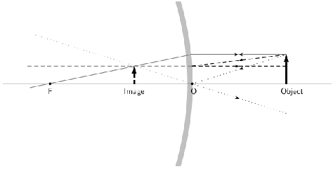
In convex mirrors, the principal axis is the same as in a plane or concave mirror, perpendicular to the center of the mirror. In this case, the focal point is behind the mirror. A convex mirror has a negative focal length because of this. The focal point is the same distance from the mirror as in a concave mirror. This is shown in.

Convex Mirror Ray Diagram: A convex mirror with three rays drawn to locate the image. Each incident ray is reflected according to the Law of Reflection. The reflected rays diverge. If the reflected rays are extended behind the mirror, then their intersection gives the location of the image behind the mirror. For a convex mirror, the image is virtual and upright.
A summary of the properties of convex mirrors is shown below:
- diverging
- virtual image
- upright
- image behind mirror
Key Points
- Reflected images can be either real or virtual. In a plane mirror, the images are virtual.
- The virtual images in a plane mirror have a left-right inversion.
- Drawing a ray diagram is a way to predict what a reflected image will look like.
- Images in mirrors can be either real or virtual.
- A summary of the properties of the concave mirrors are shown below: converging real image inverted image in front of mirror.
- A summary of the properties of the convex mirrors are shown below: diverging virtual image upright image behind mirror.
Key Terms
- virtual image: A virtual image occurs when light rays do not actually meet at the image
- concave: curved like the inner surface of a sphere or bowl
- convex: curved or bowed outward like the outside of a bowl or sphere or circle
LICENSES AND ATTRIBUTIONS
CC LICENSED CONTENT, SHARED PREVIOUSLY
- Curation and Revision. Provided by: Boundless.com. License: CC BY-SA: Attribution-ShareAlike
CC LICENSED CONTENT, SPECIFIC ATTRIBUTION
- Free High School Science Texts Project, Geometrical optics: Mirrors. September 17, 2013. Provided by: OpenStax CNX. Located at: http://cnx.org/content/m40068/latest/. License: CC BY: Attribution
- Optics. Provided by: Wikipedia. Located at: en.Wikipedia.org/wiki/Optics%23Reflections. License: CC BY-SA: Attribution-ShareAlike
- Boundless. Provided by: Boundless Learning. Located at: www.boundless.com//physics/definition/virtual-image. License: CC BY-SA: Attribution-ShareAlike
- Optics. Provided by: Wikipedia. Located at: en.Wikipedia.org/wiki/Optics%23Reflections. License: CC BY-SA: Attribution-ShareAlike
- Free High School Science Texts Project, Geometrical optics: Mirrors. September 18, 2013. Provided by: OpenStax CNX. Located at: http://cnx.org/content/m40068/latest/. License: CC BY: Attribution
- Boundless. Provided by: Boundless Learning. Located at: www.boundless.com//biology/definition/concave. License: CC BY-SA: Attribution-ShareAlike
- convex. Provided by: Wiktionary. Located at: en.wiktionary.org/wiki/convex. License: CC BY-SA: Attribution-ShareAlike
- Free High School Science Texts Project, Geometrical optics: Mirrors. December 30, 2012. Provided by: OpenStax CNX. Located at: http://cnx.org/content/m40068/latest/. License: CC BY: Attribution
- Free High School Science Texts Project, Geometrical optics: Mirrors. December 30, 2012. Provided by: OpenStax CNX. Located at: http://cnx.org/content/m40068/latest/. License: CC BY: Attribution
- Free High School Science Texts Project, Geometrical optics: Mirrors. December 30, 2012. Provided by: OpenStax CNX. Located at: http://cnx.org/content/m40068/latest/. License: CC BY: Attribution

