
4.3: Spherical Reflectors
- Page ID
- 27773

\( \newcommand{\vecs}[1]{\overset { \scriptstyle \rightharpoonup} {\mathbf{#1}} } \)
\( \newcommand{\vecd}[1]{\overset{-\!-\!\rightharpoonup}{\vphantom{a}\smash {#1}}} \)
\( \newcommand{\dsum}{\displaystyle\sum\limits} \)
\( \newcommand{\dint}{\displaystyle\int\limits} \)
\( \newcommand{\dlim}{\displaystyle\lim\limits} \)
\( \newcommand{\id}{\mathrm{id}}\) \( \newcommand{\Span}{\mathrm{span}}\)
( \newcommand{\kernel}{\mathrm{null}\,}\) \( \newcommand{\range}{\mathrm{range}\,}\)
\( \newcommand{\RealPart}{\mathrm{Re}}\) \( \newcommand{\ImaginaryPart}{\mathrm{Im}}\)
\( \newcommand{\Argument}{\mathrm{Arg}}\) \( \newcommand{\norm}[1]{\| #1 \|}\)
\( \newcommand{\inner}[2]{\langle #1, #2 \rangle}\)
\( \newcommand{\Span}{\mathrm{span}}\)
\( \newcommand{\id}{\mathrm{id}}\)
\( \newcommand{\Span}{\mathrm{span}}\)
\( \newcommand{\kernel}{\mathrm{null}\,}\)
\( \newcommand{\range}{\mathrm{range}\,}\)
\( \newcommand{\RealPart}{\mathrm{Re}}\)
\( \newcommand{\ImaginaryPart}{\mathrm{Im}}\)
\( \newcommand{\Argument}{\mathrm{Arg}}\)
\( \newcommand{\norm}[1]{\| #1 \|}\)
\( \newcommand{\inner}[2]{\langle #1, #2 \rangle}\)
\( \newcommand{\Span}{\mathrm{span}}\) \( \newcommand{\AA}{\unicode[.8,0]{x212B}}\)
\( \newcommand{\vectorA}[1]{\vec{#1}} % arrow\)
\( \newcommand{\vectorAt}[1]{\vec{\text{#1}}} % arrow\)
\( \newcommand{\vectorB}[1]{\overset { \scriptstyle \rightharpoonup} {\mathbf{#1}} } \)
\( \newcommand{\vectorC}[1]{\textbf{#1}} \)
\( \newcommand{\vectorD}[1]{\overrightarrow{#1}} \)
\( \newcommand{\vectorDt}[1]{\overrightarrow{\text{#1}}} \)
\( \newcommand{\vectE}[1]{\overset{-\!-\!\rightharpoonup}{\vphantom{a}\smash{\mathbf {#1}}}} \)
\( \newcommand{\vecs}[1]{\overset { \scriptstyle \rightharpoonup} {\mathbf{#1}} } \)
\(\newcommand{\longvect}{\overrightarrow}\)
\( \newcommand{\vecd}[1]{\overset{-\!-\!\rightharpoonup}{\vphantom{a}\smash {#1}}} \)
\(\newcommand{\avec}{\mathbf a}\) \(\newcommand{\bvec}{\mathbf b}\) \(\newcommand{\cvec}{\mathbf c}\) \(\newcommand{\dvec}{\mathbf d}\) \(\newcommand{\dtil}{\widetilde{\mathbf d}}\) \(\newcommand{\evec}{\mathbf e}\) \(\newcommand{\fvec}{\mathbf f}\) \(\newcommand{\nvec}{\mathbf n}\) \(\newcommand{\pvec}{\mathbf p}\) \(\newcommand{\qvec}{\mathbf q}\) \(\newcommand{\svec}{\mathbf s}\) \(\newcommand{\tvec}{\mathbf t}\) \(\newcommand{\uvec}{\mathbf u}\) \(\newcommand{\vvec}{\mathbf v}\) \(\newcommand{\wvec}{\mathbf w}\) \(\newcommand{\xvec}{\mathbf x}\) \(\newcommand{\yvec}{\mathbf y}\) \(\newcommand{\zvec}{\mathbf z}\) \(\newcommand{\rvec}{\mathbf r}\) \(\newcommand{\mvec}{\mathbf m}\) \(\newcommand{\zerovec}{\mathbf 0}\) \(\newcommand{\onevec}{\mathbf 1}\) \(\newcommand{\real}{\mathbb R}\) \(\newcommand{\twovec}[2]{\left[\begin{array}{r}#1 \\ #2 \end{array}\right]}\) \(\newcommand{\ctwovec}[2]{\left[\begin{array}{c}#1 \\ #2 \end{array}\right]}\) \(\newcommand{\threevec}[3]{\left[\begin{array}{r}#1 \\ #2 \\ #3 \end{array}\right]}\) \(\newcommand{\cthreevec}[3]{\left[\begin{array}{c}#1 \\ #2 \\ #3 \end{array}\right]}\) \(\newcommand{\fourvec}[4]{\left[\begin{array}{r}#1 \\ #2 \\ #3 \\ #4 \end{array}\right]}\) \(\newcommand{\cfourvec}[4]{\left[\begin{array}{c}#1 \\ #2 \\ #3 \\ #4 \end{array}\right]}\) \(\newcommand{\fivevec}[5]{\left[\begin{array}{r}#1 \\ #2 \\ #3 \\ #4 \\ #5 \\ \end{array}\right]}\) \(\newcommand{\cfivevec}[5]{\left[\begin{array}{c}#1 \\ #2 \\ #3 \\ #4 \\ #5 \\ \end{array}\right]}\) \(\newcommand{\mattwo}[4]{\left[\begin{array}{rr}#1 \amp #2 \\ #3 \amp #4 \\ \end{array}\right]}\) \(\newcommand{\laspan}[1]{\text{Span}\{#1\}}\) \(\newcommand{\bcal}{\cal B}\) \(\newcommand{\ccal}{\cal C}\) \(\newcommand{\scal}{\cal S}\) \(\newcommand{\wcal}{\cal W}\) \(\newcommand{\ecal}{\cal E}\) \(\newcommand{\coords}[2]{\left\{#1\right\}_{#2}}\) \(\newcommand{\gray}[1]{\color{gray}{#1}}\) \(\newcommand{\lgray}[1]{\color{lightgray}{#1}}\) \(\newcommand{\rank}{\operatorname{rank}}\) \(\newcommand{\row}{\text{Row}}\) \(\newcommand{\col}{\text{Col}}\) \(\renewcommand{\row}{\text{Row}}\) \(\newcommand{\nul}{\text{Nul}}\) \(\newcommand{\var}{\text{Var}}\) \(\newcommand{\corr}{\text{corr}}\) \(\newcommand{\len}[1]{\left|#1\right|}\) \(\newcommand{\bbar}{\overline{\bvec}}\) \(\newcommand{\bhat}{\widehat{\bvec}}\) \(\newcommand{\bperp}{\bvec^\perp}\) \(\newcommand{\xhat}{\widehat{\xvec}}\) \(\newcommand{\vhat}{\widehat{\vvec}}\) \(\newcommand{\uhat}{\widehat{\uvec}}\) \(\newcommand{\what}{\widehat{\wvec}}\) \(\newcommand{\Sighat}{\widehat{\Sigma}}\) \(\newcommand{\lt}{<}\) \(\newcommand{\gt}{>}\) \(\newcommand{\amp}{&}\) \(\definecolor{fillinmathshade}{gray}{0.9}\)Finding the location of an image viewed in a plane reflector is a rather simple matter, but now we will look at more interesting cases where the reflector (which we will often refer to as "mirrors," though this does not need to be specifically the case) is curved. We will not examine general curves (the analytical geometry would be quite daunting!), but will stick to spherical surfaces. Such a surface comes in two varieties – concave and convex. The former refers to a shape where the light enters the hollow region (like a cave!) before reflecting, and the latter refers to the opposite shape – one that bulges out into the region where the light is.
Concave Mirrors – Object and Image Distances
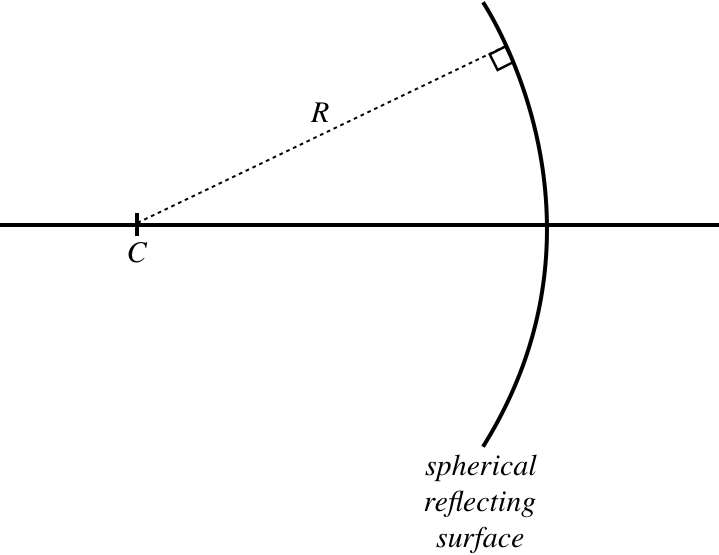
We begin by defining the geometry we are working with. This mirror’s curve is a section from a sphere, which means that if we draw lines perpendicular from its surface, the lines all intersect at a single point, which we call "\(C\)." The distance to this point from the mirror is the radius of curvature of the sphere, \(R\). The optical axis intersects the mirror perpendicularly at its center point, called its vertex.
Figure 4.3.1 – Geometry of Concave Mirror
From here we use our special trick of considering rays, rather than waves. We do this by employing the law of reflection and doing the necessary geometry. Our goal here is to use this method to derive the position of an image \(s'\) in terms of the position of the object \(s\), and the only other variable we have here, which is \(R\). The trouble is, how do we define \(s\) and \(s'\) in this case? In the case of the flat plane, every point on our object arrow (which is perpendicular to the optical axis) is the same distance from the the reflector, but that is clearly not the case for this curved surface. We therefore make the assumption that the radius of curvature of the mirror is large enough (i.e. it is flat enough) that the mirror's position can be treated like the position of a plane, and this is the position from which the quantities \(s\) and \(s'\) are measured. The result is that an object that is totally lateral (perpendicular to the optical axis) will result in an image that is also lateral.
Using this "flat approximation," we will do the geometry to find the image of a point on the object that lies on the optical axis. The diagram will be clearer for this approximation if we draw the mirror as a straight vertical line, and for no particular reason, we will choose the object to be outside of the center point of the mirror. The critical principle here is the law of reflection. A ray starting at the object that strikes the mirror will reflect off it such that the incident angle equals the reflected angle, where these angles are measured relative to the perpendicular – the radial line shown in the figure above.
Figure 4.3.2 – Image of a Point on the Optical Axis – Picture
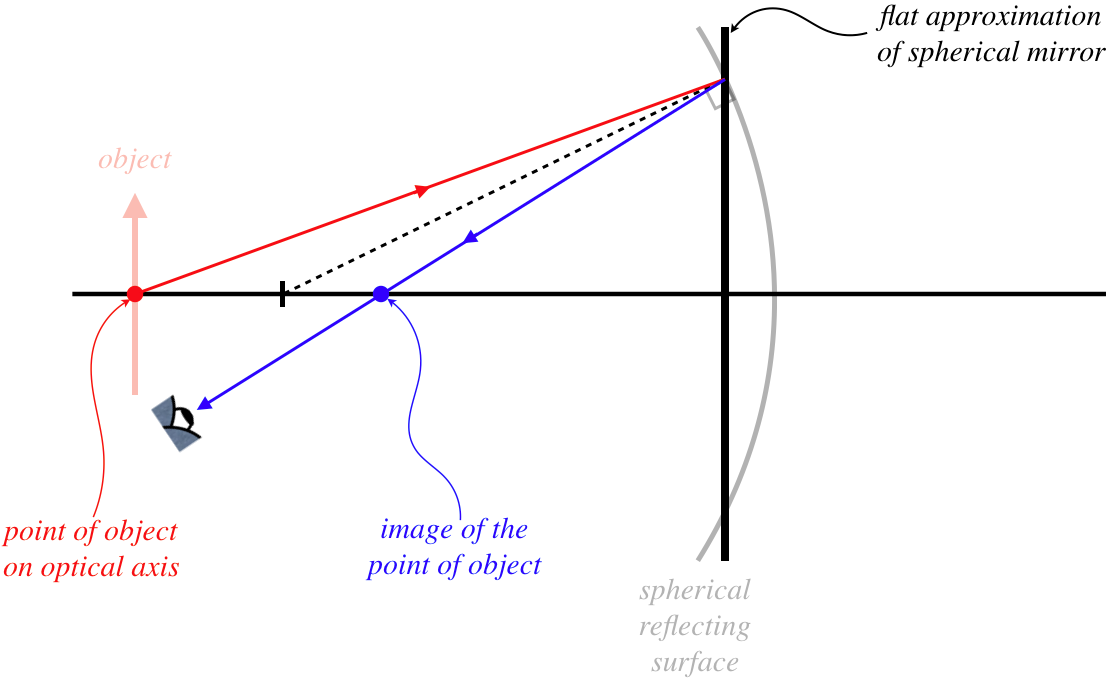
We are only looking for how the object and image distances are related here, and since we are assuming that the image remains lateral, we only need to do the calculation for a single point (we will have more work to do later to determine the nature of the full image). But how do we know that the image of this point also lies on the optical axis? Remember, just viewing a single ray is not enough to locate the image! We need a second ray. Rather than clutter our diagram, we simply note that the ray that leaves the same point heading along the optical axis strikes the mirror at a right angle, and therefore reflects straight back. That gives us a ray intersection that lands right at the point indicated – indeed the image of a point on the optical axis must also lie on the optical axis.
Digression
As with the case of the image due to a flat refractor, if one carefully sketches the rays properly for a spherical mirror, the rays actually do not all pass through a common point. For our purposes, this deviation from an exact result will not be a problem, but for optical systems involving spherical surfaces that require great precision, this unwanted blurriness of the image is a consequence of the inexactitude of the geometry known as spherical aberration.
Okay, so let's clear away the clutter of the above figure and label all the important features so that we can do some geometry and apply our usual small angle approximation...
Figure 4.3.3 – Image of a Point on the Optical Axis – Geometry
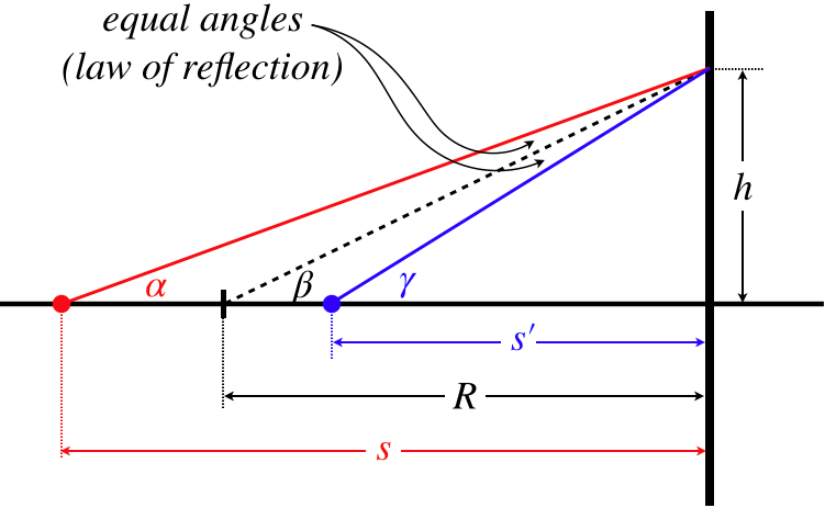
It's obvious that the angle \(\beta\) has a value that falls between the values of the angles \(\alpha\) (which is smaller) and \(\gamma\) (which is larger). But when the other two angles indicated in the triangle happen to be equal as they are in this case thanks to the law of reflection, it happens that the angle \(\beta\) is precisely the arithmetic mean of \(\alpha\) and \(\gamma\) (geometric proof of this feature of interior and exterior angles of triangles is left as an exercise for the reader). In other words:
\[\beta = \dfrac{\alpha + \gamma}{2} \;\;\;\Rightarrow\;\;\; \alpha + \gamma = 2\beta\]
We can read off the tangents of these angles, and apply the small-angle approximation to get:
Combining these equations, we get the following simple relationship between the object and image distances and the radius of curvature of the mirror:
\[\dfrac{1}{s}+\dfrac{1}{s'}=\dfrac{2}{R}\]
We have dealt with these distances as absolute values, so we need to double-check this result and make sure it satisfies our sign conventions. The light is coming into the mirror from the left, and the object is on the left, so according to our sign convention, the object distance is positive. The light leaves the mirror on the left side, and the image is on the left side, so the image is on the outgoing side, which means that it too is a positive value. With both of these values positive, the value of the \(R\) must also be positive, and this equation holds as it stands. We don't want to make any assumptions about the sign of \(R\) for a convex mirror, so for now we will just note that \(R\) is positive if the mirror is concave. Or put into the language of our conventions, \(R\) is positive if the center of the sphere is on the outgoing side of the light.
\[\begin{array}{c} \text{name} && \text{symbol} && \text{positive when} && \text{negative when} \\ object\;distance && s && object\;on\;incoming\;side && object\;on\;other\;side \\ image\;distance && s' && image\;on\;outgoing\;side && image\;on\;other\;side \\ lateral\;magnification && M && image\;upright && image\;inverted \\ radius\;of\;curvature && R && center\;of\;sphere\;on\;outgoing\;side && ???\end{array}\]
Real and Virtual Images
We arbitrarily chose a position for the object, and found that the image distance was also positive. The value of \(\frac{2}{R}\) is a fixed value, but we can move the object as close to the mirror as we like. Then the value of \(s\) can be made arbitrarily small (but still positive), which means that \(\frac{1}{s}\) can be made arbitrarily large. If this latter value exceeds the value of \(\frac{2}{R}\), then for Equation 4.3.3 to hold, the value of \(s'\) must be negative. This means that the image of an object close to the mirror lands on the side other than the outgoing side of the light, which in this case is to the right of the mirror.
At first this seems impossible – the light never gets behind the mirror, so how can the right rays possibly intersect there to make an image? This calls for an important reminder...
Alert
Images are not formed from light rays running into other light rays! First of all, it is dangerous to use the word "formed" here, because it implies that a new object is created, as though optics works like a 3-d printer. The idea of an image is simply something we invented to express the fact that the apparent source of light is different from the actual source (different in its location, size, and possibly orientation). Second, we locate the image by looking at light and tracing imaginary "rays" (which we also invented) back to their apparent origin. There is nothing in this scheme that requires actual light to intersect with itself. If the backtrack of the rays lands in a region where there is no light (as was the case for the flat reflector), then that is fine.
Let's see how this happens with a new figure. As before, a ray that follows the optical axis bounces straight back from the vertex of the mirror, so the image must lie on the optical axis, but now when the object point is close we have:
Figure 4.3.4 – Image Point Behind the Mirror

This image is found the same way as the previous image (because that is the definition of an image) – by backtracking reflected rays to the point where they intersect. Nevertheless, there seems to be something distinctly different about this image that exists where there is no light, and the previous image that exists where the actual light is. These images don't look any different – it's not like one is darker than the other or anything, but there is one small difference about them that we will discuss later. For now, we will simply give them different names. Images that exist at a point where the light actually passes are called real, and images that exist where there is not actually any light (at least no light from the object that reaches the eye) are called virtual.
Alert
These monikers of "real" and "virtual" are quite dangerous, as they often lead to great confusion. People encountering these terms tend to think that real images are "actually there," while virtual images are not. The truth is that neither is "actually there," whatever that means! Both types of images are simply where we perceive the light to be coming from – there is not actually any light emitted from that spot in either case. Don't let their names fool you into thinking there is really anything fundamentally different about these two types of images.
To understand the differences between an object, a real image, and a virtual image, it might help to think about the light once again as waves. For a point object (like the tip of our usual arrow), light travels outward in all directions in a full spherical wave. For a real image, a partial spherical wave propagates inward toward the point image, and then outward from it on the other side. For a virtual image, a partial spherical wave is moving outward only, with the point image at its center, but the wave does not exist in the immediate vicinity of the point image.
Figure 4.3.5 – Objects and Images in Terms of Light Waves
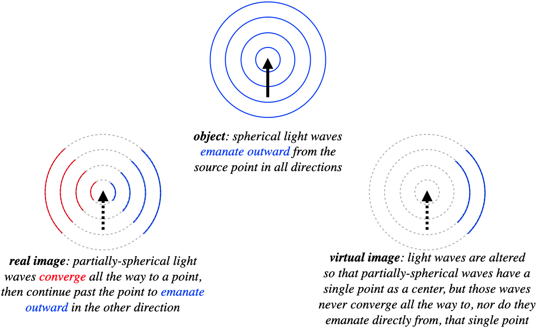
In every case, an eye viewing the outward-moving spherical light waves will trace the source back to the center of the sphere, which is the "apparent source of the light."
Concave Mirrors – Principal Rays
We can now find the image given the location of the object, either by drawing a diagram and doing the geometry for a single point, or by plugging into the equation. But this doesn't tell us everything about the image. We will now develop the geometry a little further in order to determine whether the image is larger or smaller than the object, and whether it inverts or remains upright.
We can use what we have done above to locate the one point on the image that intersects the optical axis, and to simplify matters we will place the base of the object arrow on this axis. So all we need it to find the location of the tip of the image arrow. The tip sends out spherical waves that are reflected by the mirror, which means we have an infinite number of rays to choose from to perform our geometry tricks. We only need two such rays to get an intersection point, so let's see if we can pick rays that make our job as easy as possible. It turns out that there are four such rays, called the principal rays. They are not physically any more important than any of the infinitude of other rays – they just make our task of geometry simpler.
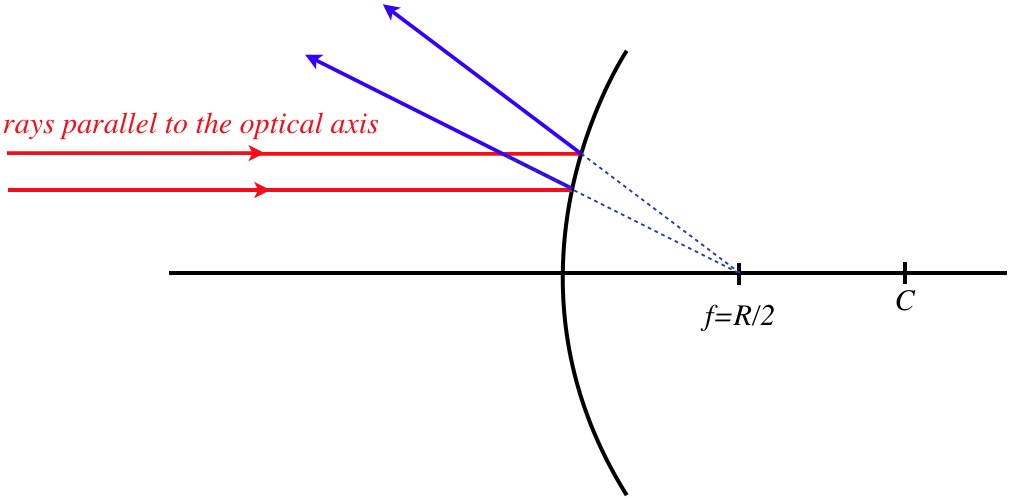
Before we describe how the principal rays are defined, we need to take a quick look back at Equation 4.3.3. We saw that the image distance can be either positive or negative, depending upon the placement of the object. What happens if we start the object far away and gradually move it closer to the mirror. At some point the image must transition from real to virtual. What is the borderline position of the object that defines this transition? Clearly this occurs when \(s=\frac{R}{2}\), which results in the image position going to infinity. What does the ray look like that passes through the image point at infinity? In this limit, the outgoing ray must be parallel to the optical axis.
Figure 4.3.6 – Image Point at Infinity Means Ray Parallel to Optical Axis

If we swap the object and image (the law of reflection doesn't care which ray is coming in or going out), so that the object is at \(s=\infty\), then the image of this point will be on the optical axis a distance of \(\frac{R}{2}\) from the mirror. This is true of every ray that strikes the mirror from a direction parallel to the optical axis. That is, every incoming light ray converges to this point, and this point is called the focal point of the mirror.
The existence of a focal point gives us two principal rays – one that comes in parallel to the optical axis (note it doesn't have to come from infinity – it still follows the same path), which reflects through the focal point, and one that passes through the focal point or comes from the direction of the focal point, which reflects parallel to the optical axis. A third principal ray is one that passes through or comes from the direction of the center point. When such a ray strikes the mirror, it hits it at a right angle, so it comes straight back. And the fourth principal ray is the one that strikes the vertex of the mirror, which reflects at the same angle with the optical axis from which it arrived. Again, these rays are "principal" only because they are easy to sketch and work with geometrically, and only two of them are needed to find the image location, though all four intersect at the same point. To summarize:
Figure 4.3.7 – Principal Rays of a Concave Spherical Mirror
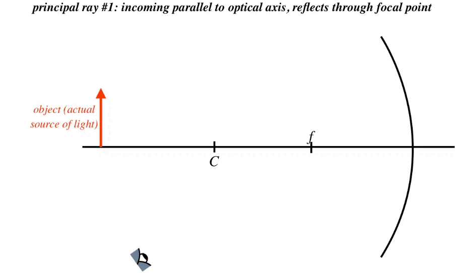
What we notice immediately is that we have our first inverted image thus far in our exploration of geometrical optics. It is also diminished in size. Both of these results are specific to the placement of the object, so one must be careful about drawing a general conclusion from this. This process of sketching the principal rays is called a ray trace, and while it is not particularly useful for quantitative work (unless, for example, you work carefully on graph paper), it does quickly give an idea of the rough position of the image, a rough measure of the lateral magnification, and the image's orientation. Shortly we will examine how to get this information through direct mathematics.
We can see the importance of the placement of the object in the final result by performing the ray trace with the object closer to the mirror than the focal point. The principal ray that comes in parallel to the axis and the ray that strikes the vertex are as easy to do as the case shown above, but what about the ray that passes through the focal point and the ray that passes through the center point? If the light from the object has to go backward to go through these points, then it will not strike the mirror at all. Do we simply have to concede that we only have two principal rays to work with? No!
The rays only represent the direction that a single point on the light wavefront is moving, so their value as a tool comes from their directions, not from there actual paths. A ray that comes to the mirror from the direction of the center point or focal point will behave after reflection exactly like a ray that does pass through those points. So all we need to do to trace these rays is start them at \(C\) or \(f\) (depending upon which ray you want), and send it through the tip of the object toward the mirror. [Note: The part of the ray where there is not actually any light is often represented with a dotted line.]
Figure 4.3.8 – Principal Rays from an Object Close to a Concave Spherical Mirror
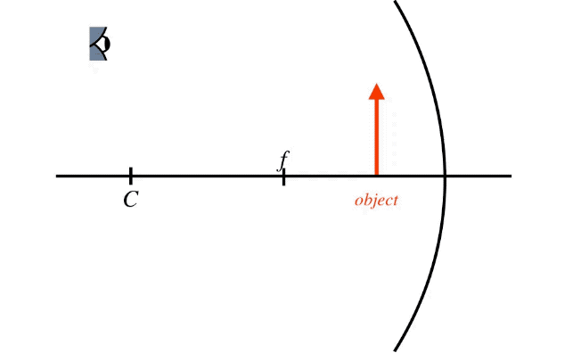
Notice that the outgoing rays don't cross each other as they did in the previous example. Again, it is only the backtracking of rays that has any meaning in our use of rays. We simply have to backtrack these rays a bit farther than before, into a region where there is no light passing through. Put another way, the previous example resulted in a real image, while this example results in a virtual image. Although the other two principal rays were omitted in the above figure, if they had been included, then they would also be backtracked to the same point in space.
Alert
The curvature of the mirror has been exaggerated for effect in the figure, and a careful ray trace should actually treat it as flat. If you try to confirm that the other principal rays converge to the same point and don't correct this flaw, you will find that they will not quite converge.
Concave Mirrors – Mathematics
The focal point is a distance of \(\frac{R}{2}\) from the mirror, a distance known as the focal length of that mirror, designated the variable \(f\) (we stopped discussing waves just in time to be able to reuse this symbol without confusing it with frequency). In terms of the focal length, Equation 4.3.3 becomes:
\[\dfrac{1}{s} + \dfrac{1}{s'} = \dfrac{1}{f} \]
So far we have only discussed concave mirrors, and we know in this context that our sign convention requires \(R>0\), which means that the same must be true for the focal length, which we now add to our list:
\[\begin{array}{c} \text{name} && \text{symbol} && \text{positive when} && \text{negative when} \\ object\;distance && s && object\;on\;incoming\;side && object\;on\;other\;side \\ image\;distance && s' && image\;on\;outgoing\;side && image\;on\;other\;side \\ lateral\;magnification && M && image\;upright && image\;inverted \\ radius\;of\;curvature && R && center\;of\;sphere\;on\;outgoing\;side && ??? \\ focal\;length && f && focal\;point\;on\;outgoing\;side && ???\end{array}\]
We already know how to compute the image distance \(s'\) from the object distance and radius of curvature. Let's look at how we can calculate the lateral magnification from these inputs. We know the lateral magnification in terms of the heights of the object and image, and with just one of the principal rays (the \(4^{th}\) one, that strikes the vertex), we can accomplish our goal.
Figure 4.3.9 – Geometry of Lateral Magnification
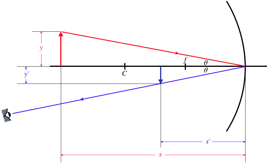
The triangles formed by the object and image are similar (the reflection angles are equal, and they are both right triangles), which means the ratios of the lengths of their sides are equal. Using this and noting that \(y\) is positive, \(y'\) is negative, and both \(s\) and \(s'\) are positive (according to our sign conventions), we have:
\[M = \dfrac{y'}{y} = -\dfrac{s'}{s} \]
This can then be combined with Equation 4.3.3 to determine the lateral magnification in terms of the placement of the object and the radius of curvature of the sphere. While this derivation of the lateral magnification was performed for the case of the real image, the same result comes out for the virtual image represented by Figure 4.3.8, and the method is exactly the same – similar triangles are formed using the ray that strikes the vertex, and the ratios are the same as here. Interestingly, because the image is not on the outgoing side of the mirror in this second case, then according to our sign conventions \(s'<0\), which makes the lateral magnification positive, and indeed the image is upright, as it should be for a positive lateral magnification!
Example \(\PageIndex{1}\)
An object is moved away from a concave mirror to a position that is twice as far from the reflecting surface. In the process, the size of the image seen in the reflection goes down by a factor of 3. Find distance that separated the object and the surface before it was moved, measured in terms of the radius of the spherical reflector.
- Solution
-
Using Equation 4.3.3, we can solve for the magnification in terms of the object distance and radius of curvature of the sphere:
\[\left. \begin{array}{l} M = -\dfrac{s'}{s} \\ \dfrac{1}{s'} = \dfrac{2}{R} - \dfrac{1}{s} \end{array} \right\}\;\;\; M=\dfrac{R}{R-2s}\nonumber\]
For the object at two different positions, there are two different magnifications. The object size never changes, so for the image to get smaller by a factor of 3, the magnification must get smaller by a factor of 3. Calling \(M_1\) the magnification at the initial object distance \(s\) and \(M_2\) the magnification at the new object distance \(2s\), we have:
\[\dfrac{1}{3} = \dfrac{M_2}{M_1} = \dfrac{\frac{R}{R-4s}}{\frac{R}{R-2s}} = \dfrac{R-2s}{R-4s} \;\;\;\Rightarrow\;\;\; s=R\nonumber\]
Convex Mirrors – Object and Image Distances
As much work as we have done above, it only covers one of the two varieties of spherical reflector. Fortunately, we will not need to repeat every single step above for convex mirrors, because the principles behind the geometrical optics involved are the same. The only difference we have to address is the way that light behaves when it is reflected off a convex surface. After that, we will see that the ray traces are fairly straightforward (assuming we fully understand the ones we have done already), and the mathematics is even easier to extend to the convex case.
The single physical principle that must be satisfied is the law of reflection. When a ray strikes a convex spherical reflector, the incoming angle and outgoing angle are measured relative to the line that emanates outward from the center of the sphere. As before, if we place our object point on the optical axis, the image point must also reside on that axis, so we can draw a basic picture of what the relative positions of the object and image should look like, as we did for the concave case in Figure 4.3.2.
Figure 4.3.10 – Image of a Point on the Optical Axis for Convex Reflector – Picture

The first thing we notice for this case upon closer examination is that the image comes out to be virtual no matter where the object is located. Using our sign conventions, we have a positive object distance (the object is on the incoming side of the mirror), and a negative image distance (the image is not on the outgoing side of the mirror). If we want to use an equation that looks anything like Equation 4.3.3, then consider when the object is very far (read "infinitely far") away... The radius of curvature has to be negative. We will incorporate this into our sign conventions shortly.
As we determined previously, an object infinitely far away produces rays that are parallel to the optical axis. In the concave case, such rays converged to the focal point of the mirror. In this case, the rays all diverge from the focal point, which in this case resides on the opposite side of the mirror. The math works out the same as before regarding the focal length's relation to the radius of curvature, namely: \(f=\frac{R}{2}\).
Figure 4.3.11 – Rays Parallel to Optical Axis Diverge from Focal Point After Reflection
focal_point.png?revision=1)
While we will not repeat the geometry here, it conveniently works out that all the math we developed before, including Equation 4.3.3 can be used unchanged for the convex mirror, provided we now treat the radius and focal length as negative numbers. That is, we can now fill-in the unknown parts of the sign conventions:
\[\begin{array}{c} \text{name} && \text{symbol} && \text{positive when} && \text{negative when} \\ object\;distance && s && object\;on\;incoming\;side && object\;on\;other\;side \\ image\;distance && s' && image\;on\;outgoing\;side && image\;on\;other\;side \\ lateral\;magnification && M && image\;upright && image\;inverted \\ radius\;of\;curvature && R && center\;of\;sphere\;on\;outgoing\;side && center\;of\;sphere\;on\;other\;side \\ focal\;length && f && focal\;point\;on\;outgoing\;side && focal\;point\;on\;other\;side \end{array}\]
Convex Mirrors – Principal Rays
When it comes to ray traces for convex spherical mirrors, we follow the same four methods as for the concave mirror, though we have to keep in mind that all images are going to turn out to be virtual, so we can never expect outgoing rays to intersect – we always have to backtrack behind the mirror to find the intersection point.
The ray that strikes the vertex of the mirror (which we called "principal ray #4" in Figure 4.3.6 above) is sketched exactly as before, but there are subtle differences for the other three principal rays.
- Principal ray #1 comes in parallel to the optical axis, and therefore reflects away from the focal point, rather that toward it as it did in the concave case.
- Principal ray #2 can't pass through the focal point as it does for the concave case, but it heads toward it. It then reflects back parallel to the optical axis.
- Principal ray #3 can't pass through the center point as it does for the concave case, but it heads toward it. This causes it to strike the surface at a right angle, so it bounces straight back.
As before, all four of these rays (to a very good approximation, if the mirror can be treated as fairly flat) appear to an observer to emanate from a common point behind the mirror, which is the position of the virtual image.
Figure 4.3.12 – Principal Rays of a Convex Mirror

We can double-check this result with the math of Equation 4.3.3, to see that everything remains consistent. We already said that a negative value of \(R\) (and\(f\)) and a positive value of \(s\) requires that the value of \(s'\) be negative, confirming that the image must be on the dark side of the mirror. In addition, for the sum of \(\frac{1}{s}\) and \(\frac{1}{s'}\) for come out negative, the absolute value of \(s'\) must be smaller than that of \(s\). This means that the image is always closer to the mirror than the object. We can see that this is true for the ray trace, and that in fact it must be true no matter where the object is placed.
Another check we can do is the lateral magnification. The ray trace shows that the image is diminished and upright. Given that the math shows that \(s'\) is always negative and always has a smaller absolute value than \(s\), this lateral magnification result is confirmed using Equation 4.3.7.
The effect of a diminished image is that a greater field of view is possible in the space occupied by the mirror. This explains why car side mirrors are convex – the greater field of view allows the driver to see blind spots. The drawback is that when the overall field of view is increased, the percentage of that field occupied by a single object (such as another car) goes down. We are accustomed to interpreting objects occupying small fractions of the field of view as being far away, which is why these mirrors often have the warning, "Objects in mirror are closer than they appear."
Example \(\PageIndex{2}\)
A spherical shell is reflective on both sides. When the reflection of an object is viewed in the convex side, the image is 40% of the size of the object. If the shell is now turned around so that the reflection is viewed in the concave side, determine the size of the image (compared to the object), and whether the image is upright or inverted. Assume that the distance between the shell and object are unchanged after the shell is rotated.
- Solution
-
In terms of the focal length of the reflector, the magnification is:
\[\left. \begin{array}{l} M = -\dfrac{s'}{s} \\ \dfrac{1}{s'} = \dfrac{1}{f} - \dfrac{1}{s} \end{array} \right\}\;\;\; M=\dfrac{f}{f-s}\nonumber\]
We are given that the magnification initially is \(\frac{2}{5}\), so solving for \(s\) in terms of \(f\) gives:
\[\dfrac{2}{5} = \dfrac{f}{f-s} \;\;\;\Rightarrow\;\;\; s = -\frac{3}{2}f\nonumber\]
The negative sign comes in because the focal length for a convex reflector is negative, while the object distance is positive. When the reflector is turned around, the focal length becomes positive, and since the distance between the object and mirror is unchanged, we now have that the object distance is: \(s=+\frac{3}{2}f\). Plugging this into the magnification gives:
\[M=\dfrac{f}{f-\frac{3}{2}f} = -2\nonumber\]
So the new image is twice as large as the object, and because the value of the magnification is negative, the image is inverted.
Video Lecture