
Sample Problems
- Page ID
- 63408

\( \newcommand{\vecs}[1]{\overset { \scriptstyle \rightharpoonup} {\mathbf{#1}} } \)
\( \newcommand{\vecd}[1]{\overset{-\!-\!\rightharpoonup}{\vphantom{a}\smash {#1}}} \)
\( \newcommand{\dsum}{\displaystyle\sum\limits} \)
\( \newcommand{\dint}{\displaystyle\int\limits} \)
\( \newcommand{\dlim}{\displaystyle\lim\limits} \)
\( \newcommand{\id}{\mathrm{id}}\) \( \newcommand{\Span}{\mathrm{span}}\)
( \newcommand{\kernel}{\mathrm{null}\,}\) \( \newcommand{\range}{\mathrm{range}\,}\)
\( \newcommand{\RealPart}{\mathrm{Re}}\) \( \newcommand{\ImaginaryPart}{\mathrm{Im}}\)
\( \newcommand{\Argument}{\mathrm{Arg}}\) \( \newcommand{\norm}[1]{\| #1 \|}\)
\( \newcommand{\inner}[2]{\langle #1, #2 \rangle}\)
\( \newcommand{\Span}{\mathrm{span}}\)
\( \newcommand{\id}{\mathrm{id}}\)
\( \newcommand{\Span}{\mathrm{span}}\)
\( \newcommand{\kernel}{\mathrm{null}\,}\)
\( \newcommand{\range}{\mathrm{range}\,}\)
\( \newcommand{\RealPart}{\mathrm{Re}}\)
\( \newcommand{\ImaginaryPart}{\mathrm{Im}}\)
\( \newcommand{\Argument}{\mathrm{Arg}}\)
\( \newcommand{\norm}[1]{\| #1 \|}\)
\( \newcommand{\inner}[2]{\langle #1, #2 \rangle}\)
\( \newcommand{\Span}{\mathrm{span}}\) \( \newcommand{\AA}{\unicode[.8,0]{x212B}}\)
\( \newcommand{\vectorA}[1]{\vec{#1}} % arrow\)
\( \newcommand{\vectorAt}[1]{\vec{\text{#1}}} % arrow\)
\( \newcommand{\vectorB}[1]{\overset { \scriptstyle \rightharpoonup} {\mathbf{#1}} } \)
\( \newcommand{\vectorC}[1]{\textbf{#1}} \)
\( \newcommand{\vectorD}[1]{\overrightarrow{#1}} \)
\( \newcommand{\vectorDt}[1]{\overrightarrow{\text{#1}}} \)
\( \newcommand{\vectE}[1]{\overset{-\!-\!\rightharpoonup}{\vphantom{a}\smash{\mathbf {#1}}}} \)
\( \newcommand{\vecs}[1]{\overset { \scriptstyle \rightharpoonup} {\mathbf{#1}} } \)
\(\newcommand{\longvect}{\overrightarrow}\)
\( \newcommand{\vecd}[1]{\overset{-\!-\!\rightharpoonup}{\vphantom{a}\smash {#1}}} \)
\(\newcommand{\avec}{\mathbf a}\) \(\newcommand{\bvec}{\mathbf b}\) \(\newcommand{\cvec}{\mathbf c}\) \(\newcommand{\dvec}{\mathbf d}\) \(\newcommand{\dtil}{\widetilde{\mathbf d}}\) \(\newcommand{\evec}{\mathbf e}\) \(\newcommand{\fvec}{\mathbf f}\) \(\newcommand{\nvec}{\mathbf n}\) \(\newcommand{\pvec}{\mathbf p}\) \(\newcommand{\qvec}{\mathbf q}\) \(\newcommand{\svec}{\mathbf s}\) \(\newcommand{\tvec}{\mathbf t}\) \(\newcommand{\uvec}{\mathbf u}\) \(\newcommand{\vvec}{\mathbf v}\) \(\newcommand{\wvec}{\mathbf w}\) \(\newcommand{\xvec}{\mathbf x}\) \(\newcommand{\yvec}{\mathbf y}\) \(\newcommand{\zvec}{\mathbf z}\) \(\newcommand{\rvec}{\mathbf r}\) \(\newcommand{\mvec}{\mathbf m}\) \(\newcommand{\zerovec}{\mathbf 0}\) \(\newcommand{\onevec}{\mathbf 1}\) \(\newcommand{\real}{\mathbb R}\) \(\newcommand{\twovec}[2]{\left[\begin{array}{r}#1 \\ #2 \end{array}\right]}\) \(\newcommand{\ctwovec}[2]{\left[\begin{array}{c}#1 \\ #2 \end{array}\right]}\) \(\newcommand{\threevec}[3]{\left[\begin{array}{r}#1 \\ #2 \\ #3 \end{array}\right]}\) \(\newcommand{\cthreevec}[3]{\left[\begin{array}{c}#1 \\ #2 \\ #3 \end{array}\right]}\) \(\newcommand{\fourvec}[4]{\left[\begin{array}{r}#1 \\ #2 \\ #3 \\ #4 \end{array}\right]}\) \(\newcommand{\cfourvec}[4]{\left[\begin{array}{c}#1 \\ #2 \\ #3 \\ #4 \end{array}\right]}\) \(\newcommand{\fivevec}[5]{\left[\begin{array}{r}#1 \\ #2 \\ #3 \\ #4 \\ #5 \\ \end{array}\right]}\) \(\newcommand{\cfivevec}[5]{\left[\begin{array}{c}#1 \\ #2 \\ #3 \\ #4 \\ #5 \\ \end{array}\right]}\) \(\newcommand{\mattwo}[4]{\left[\begin{array}{rr}#1 \amp #2 \\ #3 \amp #4 \\ \end{array}\right]}\) \(\newcommand{\laspan}[1]{\text{Span}\{#1\}}\) \(\newcommand{\bcal}{\cal B}\) \(\newcommand{\ccal}{\cal C}\) \(\newcommand{\scal}{\cal S}\) \(\newcommand{\wcal}{\cal W}\) \(\newcommand{\ecal}{\cal E}\) \(\newcommand{\coords}[2]{\left\{#1\right\}_{#2}}\) \(\newcommand{\gray}[1]{\color{gray}{#1}}\) \(\newcommand{\lgray}[1]{\color{lightgray}{#1}}\) \(\newcommand{\rank}{\operatorname{rank}}\) \(\newcommand{\row}{\text{Row}}\) \(\newcommand{\col}{\text{Col}}\) \(\renewcommand{\row}{\text{Row}}\) \(\newcommand{\nul}{\text{Nul}}\) \(\newcommand{\var}{\text{Var}}\) \(\newcommand{\corr}{\text{corr}}\) \(\newcommand{\len}[1]{\left|#1\right|}\) \(\newcommand{\bbar}{\overline{\bvec}}\) \(\newcommand{\bhat}{\widehat{\bvec}}\) \(\newcommand{\bperp}{\bvec^\perp}\) \(\newcommand{\xhat}{\widehat{\xvec}}\) \(\newcommand{\vhat}{\widehat{\vvec}}\) \(\newcommand{\uhat}{\widehat{\uvec}}\) \(\newcommand{\what}{\widehat{\wvec}}\) \(\newcommand{\Sighat}{\widehat{\Sigma}}\) \(\newcommand{\lt}{<}\) \(\newcommand{\gt}{>}\) \(\newcommand{\amp}{&}\) \(\definecolor{fillinmathshade}{gray}{0.9}\)All of the problems below have had their basic features discussed in an "Analyze This" box in this chapter. This means that the solutions provided here are incomplete, as they will refer back to the analysis performed for information (i.e. the full solution is essentially split between the analysis earlier and details here). If you have not yet spent time working on (not simply reading!) the analysis of these situations, these sample problems will be of little benefit to your studies.
Problem 5.1
A bug stands on the outer edge of a turntable as it begins to spin, accelerating rotationally in the horizontal plane from rest at a constant rate. The bug is held on the turntable by static friction, but as the turntable spins ever faster, this will not remain the case forever. The turntable, which has a radius of \(0.40m\), has its rotational speed increase at a steady rate from rest, and reaches a speed of \(\omega_1=1.2\frac{rad}{s}\) after its first full revolution.
- Find the linear speed of the bug after the turntable makes \(n\) full revolutions.
- Find the coefficient of static friction if the bug falls off after the turntable makes \(n\) full revolutions.
- Solution
-
a. In the analysis, we indicated a kinematics relationship between \(\alpha\), \(\theta\), and \(\omega\). The angular acceleration is constant, so it does not depend on the number of revolutions, and for \(n\) revolutions, \(\theta=2\pi n\), so the angular velocity after \(n\) revolutions is:
\[\omega_n^2=2\alpha\left(2\pi n\right)=\omega_1^2 n\;\;\;\Rightarrow\;\;\;\omega_n=\omega_1\sqrt{n}\nonumber\]
The linear speed is the angular speed multiplied by the radius, so:
\[v_n=r\omega_n=r\omega_1\sqrt{n}=\left(0.40m\right)\left(1.2\frac{rad}{s}\right)\sqrt{n}=\left(0.48\frac{m}{s}\right)\sqrt{n}\nonumber\]
b. In the analysis we derived a formula for the coefficient of static friction in terms of the angular velocity and acceleration. Incorporating what we found above in terms of the number of full revolutions, we get:
\[\mu_s=\frac{r\sqrt{\omega_n^4+\alpha^2}}{g}=\frac{r\sqrt{n^2\omega_1^4+\left(\frac{\omega_1^2}{4\pi }\right)^2}}{g}=\frac{r\omega_1^2}{g}\sqrt{n^2+\frac{1}{16\pi^2}}=0.059\sqrt{n^2+0.0063}\nonumber\]
Notice that unless the angular acceleration is very large so that the bug falls off very quickly – in much less than a full revolution (\(n\ll 1\)) – virtually all of the static friction force goes into maintaining the centripetal acceleration, and only a very tiny fraction of the total static friction is involved with speeding up the bug.
Problem 5.2
The Blort Corporation makes a special widget that consists of a uniform disk pivoted around an axle at the end of a rod of negligible mass, which in turn rotates about its other end. This widget has two settings: It can be set in the "locked" position so that the disk does not rotate around its axle, or the "free" position so that the disk rotates frictionlessly about the axle. The difference these settings have on the motion of the disk as the rod rotates is depicted in the figure below.
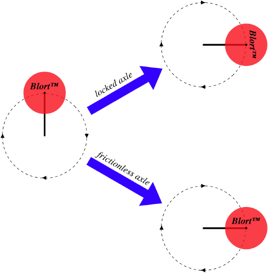
An engineer for a company that uses the Blort widgets in their manufacturing wants to make sure that the power output of the motor that turns the rod automatically adjusts so that the rod's rotation is the same whether the axle is in the fixed or free setting. The specifications of the widget indicates that the rod's length is equal to the diameter of the disk. By what factor must the power output of the motor be adjusted between these two settings?
- Solution
-
In the analysis, we calculated the kinetic energies for a given rotational speed for each of these settings. The power from the motor goes directly into the kinetic energy of the widget, so the ratio of the kinetic energies will match the ratio of the power outputs:
\[\frac{P_{locked}}{P_{free}}=\frac{ {KE}_{locked}}{ {KE}_{free}} = \dfrac{\frac{1}{4}M\left(R^2+2L^2\right)\omega^2}{\frac{1}{2}ML^2\omega^2} = 1+\frac{1}{2}\left(\frac{R}{L}\right)^2\nonumber\]
The length of the rod is the diameter of the disk, so it is twice the radius, giving:
\[\frac{P_{locked}}{P_{free}} = 1.125\nonumber\]
Problem 5.3
A solid uniform sphere starts from rest and rolls down a flat ramp without slipping.
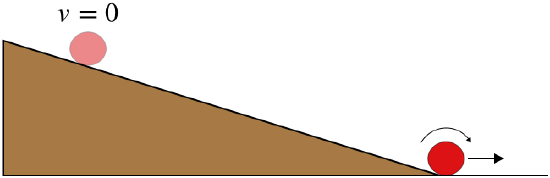
The sphere descends a vertical distance of \(3.6m\) by the time it reaches the bottom, and it takes \(6.6s\) to make the journey. Find the angle that the ramp makes with the horizontal.
- Solution
-
We know the final speed of the sphere from our analysis:
\[v_f=\sqrt{\frac{10}{7}gh}\nonumber\]
The sphere started from rest, and as noted in the analysis, the acceleration is constant, so the average velocity is:
\[v_{ave}=\frac{v_o+v_f}{2}=\sqrt{\frac{5}{14}gh}\nonumber\]
This number, along with the time, gives us the straight-line (along the ramp) distance traveled by the ball:
\[d=v_{ave}t=\sqrt{\frac{5}{14}gh}\;t\nonumber\]
We now have the hypothenuse and opposite side of a right triangle, so we can get the angle:
\[\theta = \sin^{-1}\left(\frac{h}{d}\right)=\sin^{-1}\left(\sqrt{\frac{14h}{5gt^2}}\right)=\sin^{-1}\left(\sqrt{\frac{14\left(3.6m\right)}{5\left(9.8\frac{m}{s^2}\right)\left(6.6s\right)^2}}\right)=8.8^o\nonumber\]
Problem 5.4
A solid and a hollow sphere roll without slipping simultaneously (one behind the other) down a ramp and around a loop-de-loop. The radii of the spheres are negligible compared to the radius of the loop.
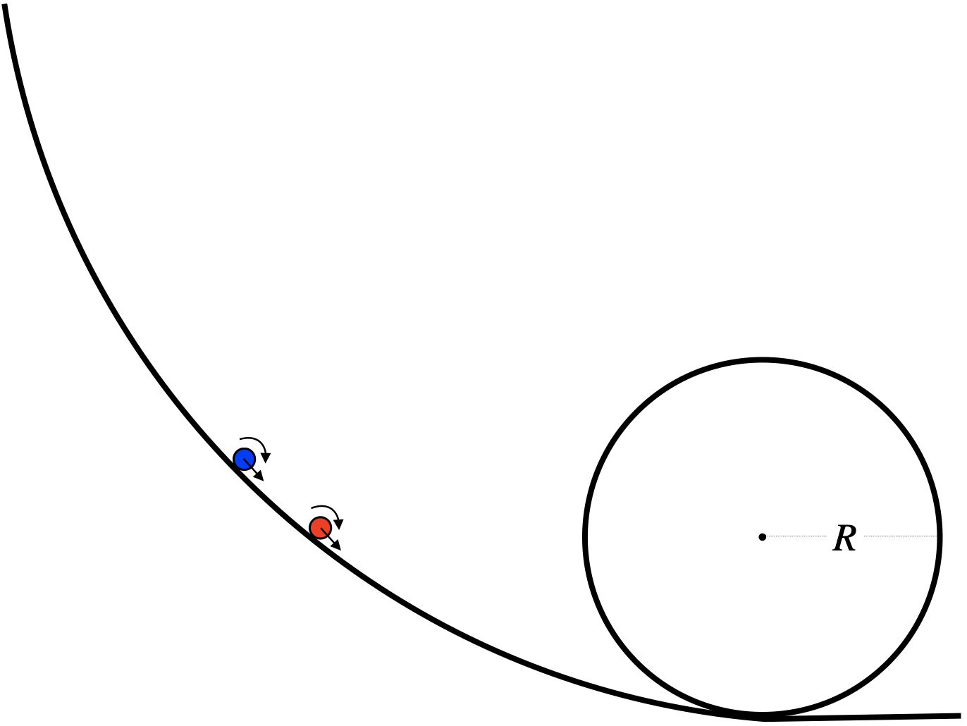
Both spheres are released simultaneously from rest, and both barely make it around the loop. Find which sphere is in front of the other, and the ratio of their starting heights.
- Solution
-
In the analysis we found that if they have the same velocity, the two spheres will have different kinetic energies. We also found the speed either sphere must have in order to get all the way around the loop. Plugging this value into the kinetic energies of the spheres tells us how much kinetic energy they must have to make it around:
\[\left.\begin{array}{l} KE_{solid}=\frac{7}{10}mv^2 \\ v=\sqrt{gR} \end{array}\right\}\;\;\; KE_{solid}=\frac{7}{10}mgR\nonumber\]
\[\left.\begin{array}{l} KE_{hollow}=\frac{5}{6}mv^2 \\ v=\sqrt{gR} \end{array}\right\}\;\;\; KE_{solid}=\frac{5}{6}mgR\nonumber\]
Referencing zero gravitational potential energy at the bottom of the loop, at the top of the loop, the spheres alsoi have a potential energy of \(2mgR\). Given that they start from rest, they start with only potential energy, so that equals their total energy:
\[E_{tot\;hollow}=mgh_{hollow}=mg\left(2R+\frac{5}{6}R\right)=\frac{17}{6}mgR\nonumber\]
\[E_{tot\;solid}=mgh_{solid}=mg\left(2R+\frac{7}{10}R\right)=\frac{27}{10}mgR\nonumber\]
The hollow sphere needs to start higher, and since they start simultaneously from rest, the leading sphere is the solid one. The ratio of their starting heights is:
\[\frac{h_{hollow}}{h_{solid}} = \frac{85}{81}\nonumber\]
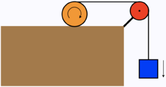
Problem 5.5
One end of a massless rope is wound around a uniform solid cylinder, while the other end passes over a massless, frictionless pulley and is attached to a hanging block, as in the diagram below. The block is released from rest, pulling the cylinder along the horizontal surface such that it rolls without slipping.
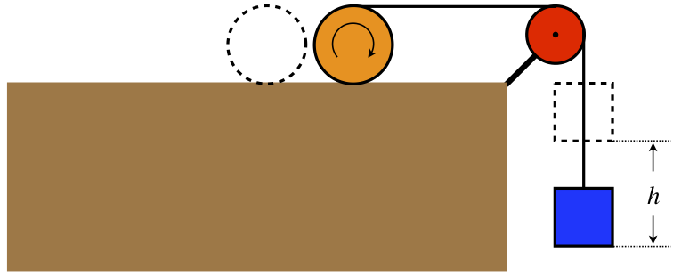
The cylinder and block are both weigh \(22N\). Find the tension in the string.
- Solution
-
In the analysis, we found the final velocity of the cylinder after the block drops a distance \(h\). Plugging in equal masses for the block and cylinder gives, and solving for the velocity of the block using, \(v_b=2v_c\):
\[v_f=2\sqrt{\frac{4m}{8m+3m}gh}=\sqrt{\frac{16}{11}gh}\nonumber\]
The acceleration of the block is constant, so from the kinematics equation with no time variable, we can get the acceleration:
\[v_f^2-v_o^2=2ay\;\;\;\Rightarrow\;\;\; a=\frac{v_f^2}{2h}=\frac{8}{11}g\nonumber\]
The acceleration is a result of the net force, which is the vector sum of the downward gravitational force and the upward tension force, so setting upward as the positive direction (making the acceleration negative), we get:
\[T-mg=ma\;\;\;\Rightarrow\;\;\;T=m\left(g+a\right)=m\left(g-\frac{8}{11}g\right)=\frac{3}{11}mg=\frac{3}{11}\left(22N\right)=6N\nonumber\]
Problem 5.6
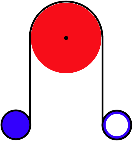
Two disks are cut out of the same material, as shown in the diagram below. They are pivoted around stationary axles such that the two disks lie in the vertical plane, with their outer rims pinching a massless rope between them. The rope is pulled downward, causing both disks to turn without the rope slipping.
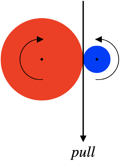
The smaller disk has one-third the radius of the larger disk. As the rope is pulled, power is delivered to the two-disk system. Find the fraction of the total power delivered to the larger disk.
- Solution
-
To find the fraction of the power delivered, we only need to figure out the ratio of the energy of the small disk to the large disk at a given speed. This ratio is:
\[\frac{ {KE}_{small}}{ {KE}_{large}}=\dfrac{\frac{1}{2}I_{small}\omega_{small}^2}{\frac{1}{2}I_{large}\omega_{large}^2}=\left(\frac{I_{small}}{I_{large}}\right)\left(\frac{\omega_{small}}{\omega_{large}}\right)^2\nonumber\]
We found these ratios in terms of the ratios of the radii of the disks in the analysis.
\[\left.\begin{array}{l} \frac{I_{small}}{I_{large}}=\left(\frac{r}{R}\right)^4 \\ \frac{\omega_{small}}{\omega_{large}}=\frac{R}{r} \end{array}\right\} \;\;\; \frac{ {KE}_{small}}{ {KE}_{large}}= \left(\frac{r}{R}\right)^2=\left(\frac{1}{3}\right)^2=\frac{1}{9}\nonumber\]
Nine times as much power goes to the large disk as the small disk, which means that 90% of the total power delivered by the pulled rope is going to the large disk.
Problem 5.7
One end of a uniform metal thin rod is welded to the outer edge of a metal disk. The masses of these two objects are the same, and the length of the rod is equal to the diameter of the disk. The disk is suspended on a frictionless axle positioned at its center, and the rod is released from rest from a horizontal orientation and allowed to swing down to the vertical position.
The linear speed of the open end of the rod at the bottom of the swing is measured to be \(3.0\frac{m}{s}\). The pendulum is then removed from the axle and is swung in the same manner (from rest horizontally) with the open end of the rod now attached to the axle (so the disk is swinging down). Find the linear speed of the bottom edge of the disk when it gets to the bottom of the swing.
- Solution
-
Let's start by using our result from the analysis to determine what is given. We know that the linear speed of the bottom of the rod is the angular velocity multiplied by the distance to the axle, so:
\[v_{rod\;end}=r\omega\;\;\;\Rightarrow\;\;\;3.0\frac{m}{s}=3R\omega_{rod\;swings}\nonumber\]
We can solve for the value of \(R\) here, but as we will soon see, this is not necessary. We do, however, have to follow all the same steps from the analysis for the new setup. First, when pivoted at the open end of the rod, the center of mass of the whole object descends a distance of \(2R\) (twice as far as the previous case), giving:
\[\Delta U = -2mg\left(2R\right)=-4mgR\nonumber\]
The moment of inertia also changes. This time we have the rod about its end and the disk extended by the parallel axis theorem:
\[I_{tot} = I_{rod}+I_{disk} = \frac{1}{3}m\left(2R\right)^2+\left[\frac{1}{2}mR^2+m\left(3R\right)^2\right] = \frac{65}{6}mR^2\nonumber\]
Putting this into the energy conservation gives:
\[{KE}_f=-\Delta U \;\;\;\Rightarrow\;\;\; \frac{1}{2}\left(\frac{65}{6}mR^2\right)\omega^2=4mgR\;\;\;\Rightarrow\;\;\; \omega=\sqrt{\frac{48g}{65R}}\nonumber\]
This is a bit slower than the previous case. The ratio of the two angular velocities are:
\[\frac{\omega_{disk\;swings}}{\omega_{rod\;swings}}=\sqrt{\frac{58}{65}}\nonumber\]
But we are interested in the linear velocity of the bottom of the disk. This is a distance of \(4R\) from the axle, so using the result above, its linear velocity is:
\[v_{disk\;bottom}=4R\omega_{disk\;swings}=4R\left(\sqrt{\frac{58}{65}}\omega_{rod\;swings}\right)=\frac{4}{3}\sqrt{\frac{58}{65}}\left(3R\omega_{rod\;swings}\right)=\sqrt{\frac{928}{585}}\left(3.0\frac{m}{s}\right)=3.8\frac{m}{s}\nonumber\]
Problem 5.8
A small marble is attached to the end of a thin rigid rod with an equal mass, whose other end is held fixed at the origin. The rod starts at rest in the \(x-y\) plane, and makes an angle \(\theta\) up from the \(x\)-axis, as shown in the diagram. There is no gravity present, but the marble (not the rod) is subjected to a force from a potential energy field given by:
\[ U\left(x,y\right)=\beta x y+U_o \;,\;\;\;\; \beta=constant>0\nonumber \]
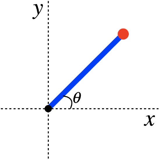
The values of the variables given above are:
\[\theta=30^o\;,\;\;\;\; \text{mass of marble}=0.45kg\;,\;\;\;\; \beta=1.2\frac{J}{m^2}\nonumber\]
- Find the magnitude and direction of the angular acceleration when the rod is released. Express the direction of this acceleration both as a unit vector and as either clockwise or counterclockwise from the perspective of this diagram.
- Find the maximum angular velocity attained by the rod, and the orientation angle of the rod when this maximum is reached.
- Solution
-
a. As usual, most of the heavy-lifting in this problem was already done in the analysis. Using the expression for the angular acceleration derived in the analysis, we have:
\[\vec\alpha=-\frac{3\beta\cos2\theta}{4m}\;\hat k=-\frac{3\left(1.2\frac{J}{m^2}\right)\cos60^o}{4(0.45kg)}\;\hat k=-1.0\frac{rad}{s^2}\hat k\nonumber\]
This vector is in the \(-\hat k\) direction, which points into the page, as we are using a right-handed coordinate system. From the RHR, this direction is clockwise from the perspective looking at the diagram.
b. Note that the linear velocity is a maximum when the rotational velocity is a maximum, so if we write the rotational velocity as a function of \(\theta\), we just need to do calculus to find where the maximum occurs:
\[0=\frac{d\omega}{d\theta}=\frac{d\omega}{dt}\frac{dt}{d\theta}=\frac{\alpha}{\omega}\;\;\;\Rightarrow\;\;\;\alpha=0\nonumber\]
From the result for the angular acceleration, we see that the extrema occur at \(\cos2\theta=0\), so \(\theta = \pm 45^o\) or \(\theta = \pm 135^o\). All of these angles satisfy \(\left|x\right| = \left|y\right|.\) Next we need to determine which ones correspond to the maximum speed. Clearly the maximum kinetic energy occurs when the potential energy is a minimum, and looking at the potential energy function, this occurs when either \(x\) or \(y\) (but not both!) is negative. These two cases correspond to \(\theta = -45^o\) and \(\theta = 135^o\). The other two angles correspond to maximum potential energies, but since the marble starts with zero kinetic energy at a lower potential energy, it can never reach these points. Therefore the only place where the marble (which starts at \(\theta=30^o\) and accelerates clockwise) can reach a maximum speed is \(\theta=-45^o\).
Let's call the length of the rod \(L\), as in the analysis. When the marble gets to \(\theta=-45^o\), the potential energy is:
\[x=-y=\frac{1}{\sqrt 2}L;\;\;\Rightarrow\;\;\;U=-\frac{1}{2}\beta L^2+U_o\nonumber\]
Initially we had:
\[\left.\begin{array}{l}x=L\cos30^o=\frac{\sqrt 3}{2}L \\ y=L\sin30^o=\frac{1}{2}L \end{array}\right\} \;\;\;\;U=\frac{\sqrt 3}{4}\beta L^2+U_o\nonumber\]
The object starts from rest, so its final kinetic energy is just equal to the amount of potential energy lost:
\[KE=-\Delta U\;\;\;\Rightarrow\;\;\;\frac{1}{2}I_{tot}\omega^2=\left(\frac{\sqrt 3}{4}\beta L^2+U_o\right)-\left(-\frac{1}{2}\beta L^2+U_o\right)=\left(\frac{\sqrt 3+2}{4}\right)\beta L^2\nonumber\]
Plugging in for the moment of inertia of the whole object as found in the analysis, we get:
\[\frac{1}{2}\left(\frac{4}{3}mL^2\right)\omega^2=\left(\frac{\sqrt 3+2}{4}\right)\beta L^2\;\;\;\Rightarrow\;\;\;\omega = \sqrt{\frac{3}{8}\left(\sqrt 3+2\right)\left(\frac{1.2\frac{J}{m^2}}{0.45kg}\right)}=1.9\frac{rad}{s}\nonumber\]
Problem 5.9
Returning to the physical system of problem 5.6, we consider a new question. As before, the cylinder rolls without slipping, and the masses are equal (though here their exact values are not known).
Find the minimum coefficient of static friction between the cylinder and the horizontal surface that will allow for this perfect rolling to occur.
- Solution
-
In the analysis we wrote down the equations that come from Newton's 2nd Law (for linear and rotational motion), and found the accelerations of the cylinder and block. The if the cylinder is just barely rolling because the coefficient of friction is as low as it can be, that means that the largest possible static friction is occurring:
\[f=\mu_sN = m_smg\nonumber\]
Putting this into the \(x\)-direction equation for the cylinder from Newton's 2nd Law, and plugging in the tension in the rope and the acceleration (both found in the analysis) gives:
\[f+T=ma\;\;\;\Rightarrow\;\;\;\mu_smg=-\frac{3}{4}ma+ma=\frac{1}{4}ma=\frac{1}{4}m\left(\frac{4}{11}g\right)\;\;\;\Rightarrow\;\;\;\mu_s=\frac{1}{11}\nonumber\]
Problem 5.10
Two ends of a massless rope are wound around two spools with equal masses and radii. One of the spools is a solid, uniform disk, while the other is a thin, hollow cylinder. The rope between them goes over a massless, frictionless pulley in a vertical plane. The spools are released from rest from the same height, and the rope does not slip over the pulley.
The radius of the pulley is \(25cm\). Find the angle through which the pulley has turned when \(2.0s\) has elapsed.
- Solution
-
From the result in the analysis, we can compute how much additional rope is in play. It is simply twice the distance that the spools fall:
\[\Delta L = 2\Delta y = 2\left(\frac{1}{2}at^2\right)=\left(\frac{3}{5}g\right)t^2=\frac{3}{5}\left(9.8\frac{m}{s^2}\right)\left(2.0s\right)^2=23.5m\nonumber\]
The torques are the same on both spools, but the solid spool has one-half the moment of inertia of the hollow one, so it has twice the angular acceleration, which means that over the same time period, it loses twice as much rope. Let's call the amount of rope lost by the hollow spool \(l\), so the amount lost by the solid spool is \(2l\). The rotation of the pulley makes up for this difference, which means it takes \(\frac{1}{2}l\) from the side where the solid spool is, and places it on the side of the hollow spool. Noting that the total rope lost by both spools combined is \(3l=\Delta L\), and using the no-slipping condition, we have:
\[s=R\theta\;\;\;\Rightarrow\;\;\; \theta = \frac{s}{R}=\frac{\frac{1}{2}l}{R}=\frac{\Delta L}{6R}=\frac{23.52m}{6\left(0.25m\right)}=15.7rad\nonumber\]
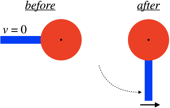
Problem 5.11
A board starts at rest and is free of any attachments (it is not pivoted on anything). It is pushed in opposite directions on both of its ends with forces of equal magnitude, at right angles to the board. The forces continue to be applied at right angles with the same magnitude, causing the board to rotate in the manner depicted in the diagram until the board has rotated by \(90^o\).
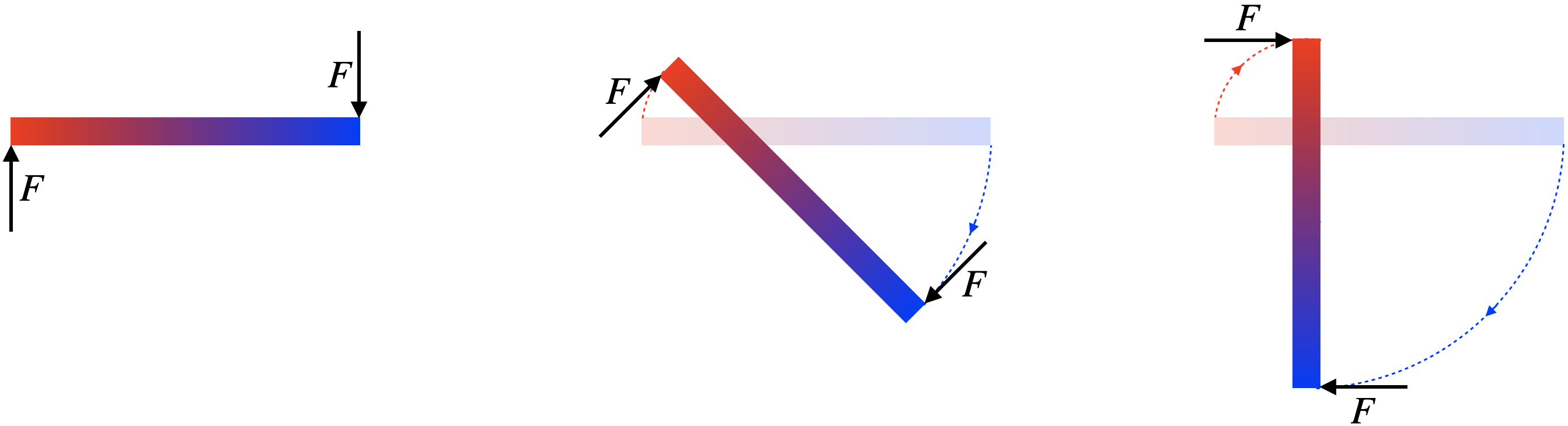
The time it takes the board to rotate the \(90^o\) is \(t\). Derive an expression for the moment of inertia of this board in terms of \( t\), the length of board \(L\), and the force \(F\).
- Solution
-
The analysis showed us that wherever the center of mass happens to be, the torque applied is still equal to \(FL\). Newton's 2nd Law for rotations gives:
\[\tau=I\alpha\;\;\;\Rightarrow\;\;\; I=\frac{\tau}{\alpha}=\frac{FL}{\alpha}\nonumber\]
The board starts from rest, and the torque remains constant, so it accelerates rotationally at a constant rate, which means its motion satisfies the usual kinematics equation:
\[\Delta\theta = \frac{1}{2}\alpha t^2\nonumber\]
We know that the rod rotates through an angle of \(\frac{\pi}{2}\) radians, and we know the time elapsed is \(t\), so we can solve for \(\alpha\) and this gives our final answer:
\[\alpha = \frac{2\Delta\theta}{t^2}=\frac{\pi}{t^2}\;\;\;\Rightarrow\;\;\;I=\frac{FLt^2}{\pi}\nonumber\]
Problem 5.12
The blob in the figure below is rigid and in static equilibrium. The two forces shown are two of the total of three forces exerted on the object.

The magnitude of \(F_1\) is three-quarters the magnitude of \(F_2\). Find the equation of the line along which the third force acts.
- Solution
-
For this object to remain in equilibrium, the net torque about every point in space must vanish. Consider the reference point \(x=-2\), \(y=+8\). Both of the given forces act through this point, so neither of them provides a torque around this reference point. There is only one more force present, and for the net torque around that reference point to be zero, the third force must also contribute zero torque, and this is only possible if that third force passes through the reference point.
In the analysis we found the tangent of the angle the force vector makes with the \(x\)-axis. This is the slope of the force line, and we are given the ratio of these two force magnitudes:
\[slope = \frac{F_2}{F_1} = \frac{4}{3}\nonumber\]
Now we know one point on the line and its slope, and these two quantities completely define it. Putting an arbitrary \(\left(x,y\right)\) point and the reference point into the slope equation gives us the equation of the line:
\[\frac{4}{3}=slope=\frac{y-y_{ref}}{x-x_{ref}}=\frac{y-8}{x+2}\;\;\;\Rightarrow\;\;\;y=\frac{4}{3}x+\frac{32}{3}\nonumber\]
Problem 5.13
Two painters carry a plank of plywood that they use for scaffolding over their heads on their way to the job site. The plank has a uniform mass distribution. Atop the plank is a can of paint weighing one third as much as the plank. The painter in the rear is holding the plank at the very end and the painter in front is holding the plank one quarter of the the plank length from the front. The can of paint is two-fifths of the plank length from the front. The plank is horizontal as they carry it.
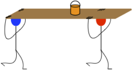
The can of paint weighs \(50N\). Find how much force each painter is exerting on the plank.
- Solution
-
As is typical for these types of problems, the analysis often solves the whole thing. In this case, we know that the plank weighs three times as much as the paint, so the total weight carried is \(200N\). We found in the analysis how the load is distributed, so we have our answers already:
\[rear\;painter=0.30\left(200N\right)=60N\;,\;\;\;\;front\;painter=0.70\left(200N\right)=140N\nonumber\]
Problem 5.14
The diagram below depicts a yo-yo on an inclined plane with its string over a massless pulley and attached to a hanging block. The whole system is in static equilibrium.
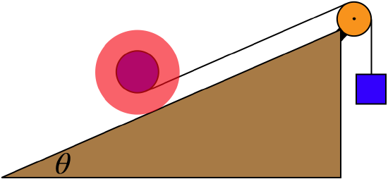
The inner radius of the yo-yo is half the outer radius, and the coefficient of friction is 0.40.
- Find the maximum angle \(\theta\) for which this system can be at static equilibrium (assume that the hanging mass can be adjusted to whatever is necessary).
- The mass of the yo-yo is \(0.35kg\). If the angle \(\theta\) is at its maximum, find the hanging weight.
- Solution
-
a. We have the equations of equilibrium from the analysis already. As the angle gets larger, the \(F_y\) equation shows that the normal force on the yo-yo by the plane gets smaller. This reduces the value of the maximum static friction force available. When the angle is so great that the new maximum friction force equals the actual friction force, then making the angle any larger would cause the yo-yo to slip. So the maximum angle without slippage means that \(f=\mu_sN\). Now we do some algebra.
Eliminate the tension first:
\[T=\frac{R}{r}f\;\;\;\Rightarrow\;\;\;\left(\frac{R}{r}-1\right)f-Mg\sin\theta=0\nonumber\]
Next eliminate the friction force:
\[f=\mu_sN\;\;\;\Rightarrow\;\;\;\left(\frac{R}{r}-1\right)\mu_sN-Mg\sin\theta=0\nonumber\]
And now the normal force:
\[N=Mg\cos\theta\;\;\;\Rightarrow\;\;\;\left(\frac{R}{r}-1\right)\mu_sMg\cos\theta-Mg\sin\theta=0\nonumber\]
Plugging-in the given \(R=2r\) and solving for \(\theta\) gives:
\[\theta = \tan^{-1}\mu_s=\tan^{-1}\left(0.4\right)=21.8^o\nonumber\]
b. Now to find the hanging mass, we need the tension. From the three equations above, we see that we can get the normal force from the mass of the yo-yo, the friction force from the normal force, and the tension from the friction:
\[mg=T=\frac{R}{r}f=\frac{R}{r}\mu_sN=\frac{R}{r}\mu_sMg\cos\theta\;\;\;\Rightarrow\;\;\;m=\left(2\right)\left(0.4\right)\left(0.35kg\right)\cos\left(21.8^o\right)\nonumber=0.26kg\]