2.6: Polarization
- Page ID
- 94102
\( \newcommand{\vecs}[1]{\overset { \scriptstyle \rightharpoonup} {\mathbf{#1}} } \)
\( \newcommand{\vecd}[1]{\overset{-\!-\!\rightharpoonup}{\vphantom{a}\smash {#1}}} \)
\( \newcommand{\id}{\mathrm{id}}\) \( \newcommand{\Span}{\mathrm{span}}\)
( \newcommand{\kernel}{\mathrm{null}\,}\) \( \newcommand{\range}{\mathrm{range}\,}\)
\( \newcommand{\RealPart}{\mathrm{Re}}\) \( \newcommand{\ImaginaryPart}{\mathrm{Im}}\)
\( \newcommand{\Argument}{\mathrm{Arg}}\) \( \newcommand{\norm}[1]{\| #1 \|}\)
\( \newcommand{\inner}[2]{\langle #1, #2 \rangle}\)
\( \newcommand{\Span}{\mathrm{span}}\)
\( \newcommand{\id}{\mathrm{id}}\)
\( \newcommand{\Span}{\mathrm{span}}\)
\( \newcommand{\kernel}{\mathrm{null}\,}\)
\( \newcommand{\range}{\mathrm{range}\,}\)
\( \newcommand{\RealPart}{\mathrm{Re}}\)
\( \newcommand{\ImaginaryPart}{\mathrm{Im}}\)
\( \newcommand{\Argument}{\mathrm{Arg}}\)
\( \newcommand{\norm}[1]{\| #1 \|}\)
\( \newcommand{\inner}[2]{\langle #1, #2 \rangle}\)
\( \newcommand{\Span}{\mathrm{span}}\) \( \newcommand{\AA}{\unicode[.8,0]{x212B}}\)
\( \newcommand{\vectorA}[1]{\vec{#1}} % arrow\)
\( \newcommand{\vectorAt}[1]{\vec{\text{#1}}} % arrow\)
\( \newcommand{\vectorB}[1]{\overset { \scriptstyle \rightharpoonup} {\mathbf{#1}} } \)
\( \newcommand{\vectorC}[1]{\textbf{#1}} \)
\( \newcommand{\vectorD}[1]{\overrightarrow{#1}} \)
\( \newcommand{\vectorDt}[1]{\overrightarrow{\text{#1}}} \)
\( \newcommand{\vectE}[1]{\overset{-\!-\!\rightharpoonup}{\vphantom{a}\smash{\mathbf {#1}}}} \)
\( \newcommand{\vecs}[1]{\overset { \scriptstyle \rightharpoonup} {\mathbf{#1}} } \)
\( \newcommand{\vecd}[1]{\overset{-\!-\!\rightharpoonup}{\vphantom{a}\smash {#1}}} \)
Polarization Filters (Polaroids)
As stated previously when discussing the speed of light waves through transparent media, the mechanisms that govern light propagation through media are complicated. There is little we can say about it in this class, except to say that because the light wave is electromagnetic in nature, it interacts with electric charge, which is present in all matter. It so happens that it is possible to construct a solid substance which greatly restricts oscillatory motion of electric charges along a single dimension. The upshot of this is that the charges react to electric fields along one direction (or rather, components of electric fields along one direction), while they don't react along a perpendicular direction.
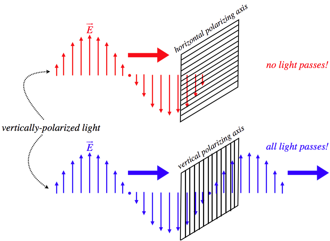
This material can have a dramatic effect on light passing through it. If the light is plane-polarized (see Figure 2.1.1), then its propagation through a medium will be affected by the preferential orientation of charge oscillations. When the light polarization is aligned with what we define as the polarizing axis of the substance, then little of the light is absorbed by the substance (i.e. the substance is transparent to this light), while if the light is polarized perpendicular to the polarizing axis, then virtually all of the light is absorbed. Such a filter is called a polaroid or polarizer.
Figure 2.6.1 – Light Through a Polaroid

One interesting application of this phenomenon is 3-D movies. Long ago someone came up with a brilliant idea for making movies projected onto a 2-D screen appear in 3-D. The idea is based on the fact that a large component (but not the only one) of seeing in 3-D is stereo vision. Your right eye sees objects from one perspective, while your left eye sees it from a slightly different perspective. You can see this is true by holding up your finger in a fixed position and alternately opening-and-closing each eye. Your finger’s position appears to change relative to the background. This inventor’s idea was to project not one but two images on the same screen. One image is recorded from the perspective of the right eye, and the other from the perspective of the left eye. Then the trick is to make the right-perspective image invisible to the left eye and the left-perspective image invisible to the right eye, so that each eye sees only its own perspective. The original inventor did this with colors – red lenses obscure red images, and yellow lenses obscure yellow light, so films were recorded from two perspectives, and each perspective was projected in a different color – one red and one yellow. But today we like our movies to be in realistic colors, so someone came up with the idea of projecting the two images with differently-polarized light, and then give viewers glasses that only admit the properly-polarized light into the respective eyes.
We have overly-simplified things here, in a couple of ways. First of all, a light wave does not have to arrive at the polarizer in either a parallel or perpendicular orientation – it could be aligned at any angle with the polarizing axis. What happens then? Well, electric fields are vector fields, which means they can be broken into components, so the component of the electric field that is parallel to the polarizing axis gets through, and the other component is absorbed.
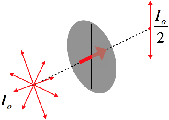
The second oversimplification is that not all of the individual light waves that come from a source are necessarily polarized in the same direction. In fact “natural” light from light bulbs and the sun is “unpolarized,” which comes about because each of the individual light sources (atoms) are aligned in random orientations, and all send out random, unaligned light waves. When such light is passed through a polaroid, half the light gets through. To see why this should be so, break every electric field vector of every wave into components parallel and perpendicular to the polarizing axis. Because the wave polarization directions are randomly-oriented, there is no reason to expect there to be a greater sum of components along one axis than another. By “half the light gets through,” what do we mean? We mean that the intensity drops by one half. We look at the more general case of intensity next.
Intensity
We can express the fact that half of natural light gets through a polaroid in a diagram as follows:
Figure 2.6.2 – Natural Light Intensity Halves Through a Polaroid

Now let's consider what happens if we send the natural light through two polaroids in succession. Clearly when the light reaches the second polaroid it will be plane-polarized from the first one. If the second polaroid is oriented the same as the first, then all the light gets through, and the intensity is unchanged, and if its polarizing axis is at right angles to the first polaroid, then no light will get through it. But now we seek to determine the intensity of the light that passes through the second polaroid if the angle between their polarizing axes is somewhere between \(0^o\) and \(90^o\).
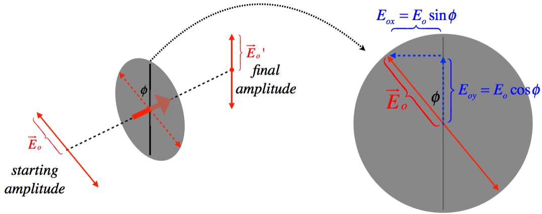
This process all comes down to what happens to the electric field vectors. After passing through the first polaroid, all the electric field vectors are aligned with that polaroid's polarizing axis. When those vectors come upon the second polaroid, just the component of the field vector that is aligned with the new axis gets through, resulting in a new vector shorter than the original.
Figure 2.6.3 – Polarized Light Through a Polaroid

Resolving the original electric field vector into components parallel and perpendicular to the polarizing axis, and keeping only the parallel part means that the new electric field vector magnitude is:
\[E_o' = E_o \cos\phi\]
The electric field vector is the amplitude of the light wave, and we are interested in the intensity. As with any other wave, the intensity is proportional to the square of the amplitude, so the relationship between the outgoing intensity \(I\) and incoming intensity \(I_o\) is:
\[I = I_o\cos^2\phi \]
This is known as Malus's law. Notice that it works exactly as we expect for the cases where the angle happens to be \(0^o\) and \(90^o\).
Example \(\PageIndex{1}\)
Unpolarized light enters a series of four polaroids with axes of polarization that are each rotated \(30^o\) clockwise from the previous polaroid, making angles of \(0^o\), \(30^o\), \(60^o\), and \(90^o\) with some common reference point. What fraction of the intensity of the incoming light is the intensity of the outgoing light?
- Solution
-
When the unpolarized light passes through the first filter, the intensity is cut in half and comes out polarized at \(0^o\). Then it passes through three successive filters, and applying Malus’s law for each \(30^o\) change of polarization angle brings in a factor of 0.75 for each polaroid. The result is that the final intensity is:
\[I = I_o\left(\dfrac{1}{2}\right)\left(\cos^2 30^o\right)^3 = I_o\left(\dfrac{1}{2}\right)\left(\dfrac{3}{4}\right)^3=\dfrac{27}{128}I_o \nonumber\]
One might expect that since the first and last polaroids are at right angles to each other, no light at all should emerge from the last polaroid. But when the light passes through a polaroid, it gains a new polarization aligned with that polaroid's polarization axis, and has no "memory" of its previous plane of polarization. Unless two consecutive polaroids are at right angles, some light will always get through each polaroid.
Polarization By Reflection
While most natural light is unpolarized and we can polarize it with a polaroid, it turns out that is not the only way it can be polarized. A more “natural” way to create polarized light exists thanks to reflection. As we have said many times, when light (or any wave) strikes an interface between two media, it is partially transmitted and partially reflected.
Consider the following scenario: Light polarized in the vertical direction strikes an interface between media such that the reflected ray aligns with the electric field vectors of the transmitted ray. There is an important principle in physics that states that the conditions at the boundary have to work out properly. This means that the electric field vector of the incoming light must add up properly to the electric field after striking the interface. The electric field vector can of course be written in components with the “x-direction” being the electric field direction of the transmitted wave, and the “y-direction” being the direction of the reflected ray (which is perpendicular to the transmitted ray). But the outgoing light cannot have an electric field vector pointing along its direction of motion (light is a transverse wave), so no light reflects!
Figure 3.7.4 – Reflection of Polarized Light

Perhaps a more physically-intuitive and satisfying (if less mathematically rigorous) explanation for this effect involves the role of the electric charges. The electric field in the EM wave exerts forces on electric charges in the material from which the wave is reflecting, and these forces cause the charges to oscillate along those electric field directions. The oscillating charges in turn produce their own EM wave, which propagates in a direction perpendicular to their oscillations. At the angle shown above, the charges in medium #2 are oscillating in a direction parallel to the direction that a reflected wave needs to go according to the law of reflection, but charges cannot produce light waves parallel to their direction of oscillation, so no wave is reflected.
Of course this result is only for vertically-polarized incoming light, so unpolarized light that reflects at this angle will have its vertical component removed, which means that the reflected light is horizontally-polarized. More generally, light that is reflected off a surface at just the right angle will be polarized parallel to that surface. It also happens that if the angle is not just right, then while the light is not entirely polarized, it is partially so (depending upon how close to the correct angle the reflection is). By "partially polarized," we mean that the amplitude of light waves measured (using a polaroid) along one direction is not the same as the amplitude measured along the orthogonal direction. In practice this means that a polaroid aligned parallel to a surface from which the light is reflected will admit more light than a polaroid aligned perpendicular to that surface.
We can easily write down an expression for the "special angle" at which total polarization occurs (this is known as the Brewster angle), by noting that for this angle the reflected ray makes a right angle with the transmitted ray (because the field vector of the transmitted wave is perpendicular to the transmitted ray and is parallel to the reflected ray). Combining this fact with Snell's law gives the Brewster angle, \(\theta_B\):
\[n_1\sin\theta_B = n_2\sin\theta_2 = n_2\sin\left(90^o-\theta_B\right) = n_2\cos\theta_B \;\;\;\Rightarrow\;\;\; \tan\theta_B=\dfrac{n_2}{n_1} \; , \]
where \(n_1\) is the index of refraction of the medium within which the reflection is occurring, and \(n_2\) is the index of refraction of the medium off which the reflection is occurring.
A nice application of this effect involves polaroid sunglasses. Most glare from sunlight comes off surfaces that are horizontal (roads, lake surfaces, etc.), which means that the light that reflects off such surfaces has a relatively small fraction of its polarization in the vertical direction. This means that if we place polaroids in front of our eyes that are allow only vertically-polarized light to pass, then very little of the horizontally-polarized glare gets through. Of course, only half of the non-glare light gets through as well, but at least one's vision of light of important objects (on coming cars or boats, etc.) does not have to compete with the incoming light from glare.
Example \(\PageIndex{2}\)
A paleontologist is looking for the remains of a wooly mammoth in an unusually clear section of a glacier. The glare off the ice from the sun makes it hard for her to see, so she puts on her polarized sun glasses and is immediately rewarded when, along the line where the glare is cut to zero, she finds what she is looking for. Now she just needs to figure out how deep the carcass is. Fortunately she has a physicist (you) on staff. You measure the height of her eyes above the ice surface to be \(6\;ft\), and you measure the distance from the position where she first saw the beast through the glare, to the point where you can look straight down at it. This distance is \(18.4\;ft\). You estimate the index of refraction of the ice to be 1.4. Find the depth of the wooly mammoth.

- Solution
-
For the polarized sunglasses to remove all the glare, the angle the light makes with the perpendicular to the ice must be Brewster’s angle, so:
\[\tan\theta = \dfrac{n_2}{n_1} = 1.4 \nonumber \]
From the right triangle on the left, we can derive the distance from the paleontologist to the point of reflection:
\[\tan\theta = \dfrac{x_1}{6\;ft} \;\;\;\Rightarrow\;\;\; x_1 = \left(1.4\right)\left(6\;ft\right) = 8.4\;ft \nonumber\]
We can use this distance to derive the horizontal distance from the point of reflection to the point on the ice directly above the mammoth:
\[x_2 = 18.4\;ft - 8.4\;ft = 10.0\;ft \nonumber\]
The Brewster angle occurs when the reflected light makes a right angle with the transmitted light, and from symmetry (just reverse the direction of the light to see this), that is also true of the incoming glare and the light from the mammoth. Therefore we can use \(x_2\) and the tangent of the angle to get the depth:
\[\tan\theta = \dfrac{y}{x_2}\;\;\;\Rightarrow\;\;\;y=\left(1.4\right)\left(10.0\;ft\right)=14.0ft \nonumber\]


