
3.3: Mathematics of Interference


- Last updated
- Mar 16, 2025
- Save as PDF

( \newcommand{\kernel}{\mathrm{null}\,}\)
By the end of this section, you will be able to:
- Determine the angles for bright and dark fringes for double slit interference
- Calculate the positions of bright fringes on a screen
Figure 3.3.1a shows how to determine the path length difference Δl for waves traveling from two slits to a common point on a screen. If the screen is a large distance away compared with the distance between the slits, then the angle θ between the path and a line from the slits to the screen ( 3.3.1b) is nearly the same for each path. In other words, r1 and r2 are essentially parallel. The lengths of r1 and r2 differ by Δl, as indicated by the two dashed lines in the 3.3.1.
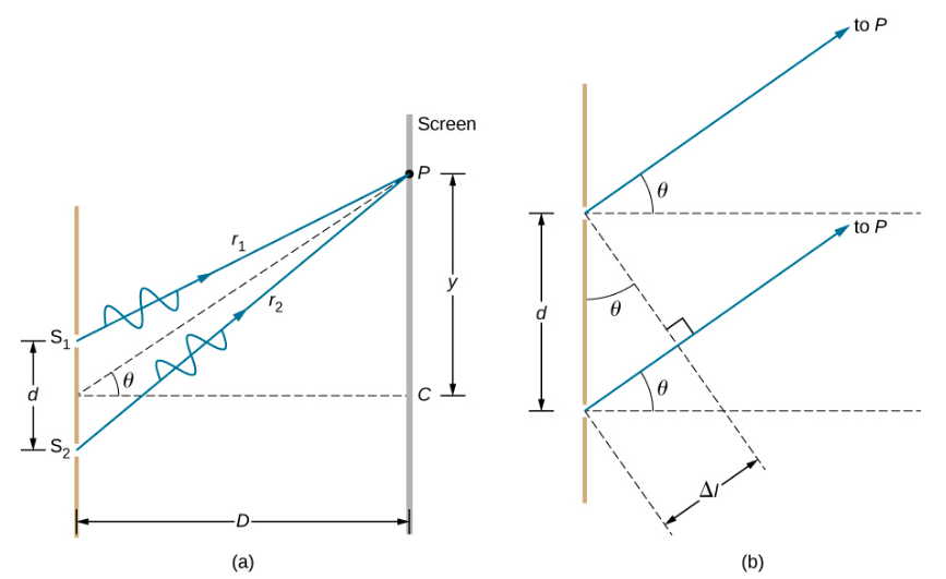
Simple trigonometry shows
Δl=dsinθ
where d is the distance between the slits. Combining this with the interference equations discussed previously, we obtain constructive interference for a double slit when the path length difference is an integral multiple of the wavelength, or
dsinθ=mλ⏟constructive interference
and
dsinθ=(m+12)λ⏟destructive interference
where
- m=0,±1,±2,±3…,
- λ is the wavelength of the light,
- d is the distance between slits, and
- θ is the angle from the original direction of the beam as discussed above.
We call m the order of the interference. For example, m=4 is fourth-order interference.
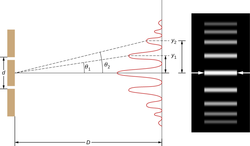
Equations ??? and ??? for double-slit interference imply that a series of bright and dark lines are formed. For vertical slits, the light spreads out horizontally on either side of the incident beam into a pattern called interference fringes (Figure 3.3.2). The closer the slits are, the more the bright fringes spread apart. We can see this by examining the Equation ???. For fixed λ and m, the smaller d is, the larger θ must be, since sinθ=mλ/d. This is consistent with our contention that wave effects are most noticeable when the object the wave encounters (here, slits a distance d apart) is small. Small d gives large θ, hence, a large effect.
Referring back to Figure 3.3.1a, θ is typically small enough that
sinθ≈tanθ≈ym/D
where ym is the distance from the central maximum to the m-th bright fringe and D is the distance between the slit and the screen. Equation ??? may then be written as
dymD=mλ
or
ym=mλDd.
Suppose you pass light from a He-Ne laser through two slits separated by 0.0100 mm and find that the third bright line on a screen is formed at an angle of 10.95° relative to the incident beam. What is the wavelength of the light?
Strategy
The phenomenon is two-slit interference as illustrated in Figure 3.3.2 and the third bright line is due to third-order constructive interference, which means that m=3. We are given d=0.0100mm and θ=10.95o. The wavelength can thus be found using Equation ??? for constructive interference.
Solution
Solving Equation ??? for the wavelength λ gives
λ=dsinθm.
Substituting known values yields
λ=(0.0100mm)(sin10.95o)3=6.33×10⁻⁴mm=633nm.
Significance
To three digits, this is the wavelength of light emitted by the common He-Ne laser. Not by coincidence, this red color is similar to that emitted by neon lights. More important, however, is the fact that interference patterns can be used to measure wavelength. Young did this for visible wavelengths. This analytical technique is still widely used to measure electromagnetic spectra. For a given order, the angle for constructive interference increases with λ, so that spectra (measurements of intensity versus wavelength) can be obtained.
Interference patterns do not have an infinite number of lines, since there is a limit to how big m can be. What is the highest-order constructive interference possible with the system described in the preceding example?
Strategy
Equation ??? describes constructive interference from two slits. For fixed values of d and λ, the larger m is, the larger sinθ is. However, the maximum value that sinθ can have is 1, for an angle of 90°. (Larger angles imply that light goes backward and does not reach the screen at all.) Let us find what value of m corresponds to this maximum diffraction angle.
Solution
Solving the equation dsinθ=mλ for m gives
m=dsinθλ.
Taking sinθ=1 and substituting the values of d and λ from the preceding example gives
m=(0.0100mm)(1)633nm≈15.8.
Therefore, the largest integer m can be is 15, or m=15.
Significance
The number of fringes depends on the wavelength and slit separation. The number of fringes is very large for large slit separations. However, recall (see The Propagation of Light) that wave interference is only prominent when the wave interacts with objects that are not large compared to the wavelength. Therefore, if the slit separation and the sizes of the slits become much greater than the wavelength, the intensity pattern of light on the screen changes, so there are simply two bright lines cast by the slits, as expected, when light behaves like rays. We also note that the fringes get fainter farther away from the center. Consequently, not all 15 fringes may be observable.
In the system used in the preceding examples, at what angles are the first and the second bright fringes formed?
- Answer
-
3.63o and 7.27o, respectively