Physics LibreTexts

6.5: Rotational Inertia

  • Page ID
    104140
  • \( \newcommand{\vecs}[1]{\overset { \scriptstyle \rightharpoonup} {\mathbf{#1}} } \)

    \( \newcommand{\vecd}[1]{\overset{-\!-\!\rightharpoonup}{\vphantom{a}\smash {#1}}} \)

    \( \newcommand{\id}{\mathrm{id}}\) \( \newcommand{\Span}{\mathrm{span}}\)

    ( \newcommand{\kernel}{\mathrm{null}\,}\) \( \newcommand{\range}{\mathrm{range}\,}\)

    \( \newcommand{\RealPart}{\mathrm{Re}}\) \( \newcommand{\ImaginaryPart}{\mathrm{Im}}\)

    \( \newcommand{\Argument}{\mathrm{Arg}}\) \( \newcommand{\norm}[1]{\| #1 \|}\)

    \( \newcommand{\inner}[2]{\langle #1, #2 \rangle}\)

    \( \newcommand{\Span}{\mathrm{span}}\)

    \( \newcommand{\id}{\mathrm{id}}\)

    \( \newcommand{\Span}{\mathrm{span}}\)

    \( \newcommand{\kernel}{\mathrm{null}\,}\)

    \( \newcommand{\range}{\mathrm{range}\,}\)

    \( \newcommand{\RealPart}{\mathrm{Re}}\)

    \( \newcommand{\ImaginaryPart}{\mathrm{Im}}\)

    \( \newcommand{\Argument}{\mathrm{Arg}}\)

    \( \newcommand{\norm}[1]{\| #1 \|}\)

    \( \newcommand{\inner}[2]{\langle #1, #2 \rangle}\)

    \( \newcommand{\Span}{\mathrm{span}}\) \( \newcommand{\AA}{\unicode[.8,0]{x212B}}\)

    \( \newcommand{\vectorA}[1]{\vec{#1}}      % arrow\)

    \( \newcommand{\vectorAt}[1]{\vec{\text{#1}}}      % arrow\)

    \( \newcommand{\vectorB}[1]{\overset { \scriptstyle \rightharpoonup} {\mathbf{#1}} } \)

    \( \newcommand{\vectorC}[1]{\textbf{#1}} \)

    \( \newcommand{\vectorD}[1]{\overrightarrow{#1}} \)

    \( \newcommand{\vectorDt}[1]{\overrightarrow{\text{#1}}} \)

    \( \newcommand{\vectE}[1]{\overset{-\!-\!\rightharpoonup}{\vphantom{a}\smash{\mathbf {#1}}}} \)

    \( \newcommand{\vecs}[1]{\overset { \scriptstyle \rightharpoonup} {\mathbf{#1}} } \)

    \( \newcommand{\vecd}[1]{\overset{-\!-\!\rightharpoonup}{\vphantom{a}\smash {#1}}} \)

    \(\newcommand{\avec}{\mathbf a}\) \(\newcommand{\bvec}{\mathbf b}\) \(\newcommand{\cvec}{\mathbf c}\) \(\newcommand{\dvec}{\mathbf d}\) \(\newcommand{\dtil}{\widetilde{\mathbf d}}\) \(\newcommand{\evec}{\mathbf e}\) \(\newcommand{\fvec}{\mathbf f}\) \(\newcommand{\nvec}{\mathbf n}\) \(\newcommand{\pvec}{\mathbf p}\) \(\newcommand{\qvec}{\mathbf q}\) \(\newcommand{\svec}{\mathbf s}\) \(\newcommand{\tvec}{\mathbf t}\) \(\newcommand{\uvec}{\mathbf u}\) \(\newcommand{\vvec}{\mathbf v}\) \(\newcommand{\wvec}{\mathbf w}\) \(\newcommand{\xvec}{\mathbf x}\) \(\newcommand{\yvec}{\mathbf y}\) \(\newcommand{\zvec}{\mathbf z}\) \(\newcommand{\rvec}{\mathbf r}\) \(\newcommand{\mvec}{\mathbf m}\) \(\newcommand{\zerovec}{\mathbf 0}\) \(\newcommand{\onevec}{\mathbf 1}\) \(\newcommand{\real}{\mathbb R}\) \(\newcommand{\twovec}[2]{\left[\begin{array}{r}#1 \\ #2 \end{array}\right]}\) \(\newcommand{\ctwovec}[2]{\left[\begin{array}{c}#1 \\ #2 \end{array}\right]}\) \(\newcommand{\threevec}[3]{\left[\begin{array}{r}#1 \\ #2 \\ #3 \end{array}\right]}\) \(\newcommand{\cthreevec}[3]{\left[\begin{array}{c}#1 \\ #2 \\ #3 \end{array}\right]}\) \(\newcommand{\fourvec}[4]{\left[\begin{array}{r}#1 \\ #2 \\ #3 \\ #4 \end{array}\right]}\) \(\newcommand{\cfourvec}[4]{\left[\begin{array}{c}#1 \\ #2 \\ #3 \\ #4 \end{array}\right]}\) \(\newcommand{\fivevec}[5]{\left[\begin{array}{r}#1 \\ #2 \\ #3 \\ #4 \\ #5 \\ \end{array}\right]}\) \(\newcommand{\cfivevec}[5]{\left[\begin{array}{c}#1 \\ #2 \\ #3 \\ #4 \\ #5 \\ \end{array}\right]}\) \(\newcommand{\mattwo}[4]{\left[\begin{array}{rr}#1 \amp #2 \\ #3 \amp #4 \\ \end{array}\right]}\) \(\newcommand{\laspan}[1]{\text{Span}\{#1\}}\) \(\newcommand{\bcal}{\cal B}\) \(\newcommand{\ccal}{\cal C}\) \(\newcommand{\scal}{\cal S}\) \(\newcommand{\wcal}{\cal W}\) \(\newcommand{\ecal}{\cal E}\) \(\newcommand{\coords}[2]{\left\{#1\right\}_{#2}}\) \(\newcommand{\gray}[1]{\color{gray}{#1}}\) \(\newcommand{\lgray}[1]{\color{lightgray}{#1}}\) \(\newcommand{\rank}{\operatorname{rank}}\) \(\newcommand{\row}{\text{Row}}\) \(\newcommand{\col}{\text{Col}}\) \(\renewcommand{\row}{\text{Row}}\) \(\newcommand{\nul}{\text{Nul}}\) \(\newcommand{\var}{\text{Var}}\) \(\newcommand{\corr}{\text{corr}}\) \(\newcommand{\len}[1]{\left|#1\right|}\) \(\newcommand{\bbar}{\overline{\bvec}}\) \(\newcommand{\bhat}{\widehat{\bvec}}\) \(\newcommand{\bperp}{\bvec^\perp}\) \(\newcommand{\xhat}{\widehat{\xvec}}\) \(\newcommand{\vhat}{\widehat{\vvec}}\) \(\newcommand{\uhat}{\widehat{\uvec}}\) \(\newcommand{\what}{\widehat{\wvec}}\) \(\newcommand{\Sighat}{\widehat{\Sigma}}\) \(\newcommand{\lt}{<}\) \(\newcommand{\gt}{>}\) \(\newcommand{\amp}{&}\) \(\definecolor{fillinmathshade}{gray}{0.9}\)

    Rotational Kinetic Energy

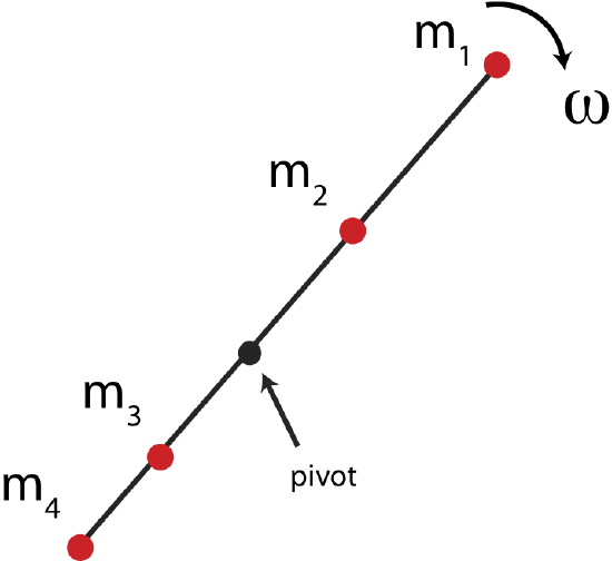
    Recall that kinetic energy is described by the mass of the object and its speed. For rotating bodies there must be an analog to kinetic energy as well. We already have a relationship between linear and angular speed, which we can use to redefine kinetic energy for rotational motion. Let us simplify our wheel example by observing a few point masses rotating on a massless rod as shown in Figure 7.4.1 below. The pivot shown in the figure defines a fixed point about which the object rotates. In some cases it is an obvious choice, such as in this example since we are assuming rod is help in place at a pilot. In other examples a rotating object might not be fixed at a particular point, but will still rotate about the center-of-mass of the object, which we will discuss later.

    Figure 7.4.1: Rotational Kinetic Energy

    wheel-inertia.png

    In this scenario the total kinetic energy of the rotating object is the sum of the kinetic energies of the four masses shown. For mass 1, \(m_1\), we can write down the kinetic energy in terms of linear speed, and then use the relationship between angular and linear speeds, \(v_1=r_1\omega\), where \(r_1\) is the distance from the pivot to the location of \(m_1\):

    \[KE=\frac{1}{2}m_1v_1^2=\frac{1}{2}m_1(r_1\omega)^2=\frac{1}{2}m_1r_1^2\omega^2\]

    The expression is similar for all the other masses, using the appropriate distances from the pivot and recognizing that all masses will rotate with the same angular velocity, \(\omega\). The total kinetic energy for this rotating object would be the sum of all the individual kinetic energies:

    \[KE=\sum_{i=1}^{4}\frac{1}{2}m_iv_i^2=\frac{1}{2}(m_1r_1^2+m_2r_2^2+m_3r_3^2+m_4r_4^2)\omega^2\]

    In general, for a set of N masses, the kinetic energy of a rotating object about a fixed pivot becomes:

    \[KE=\sum_{i=1}^{N}\frac{1}{2}m_iv_i^2=\frac{1}{2}\Big(\sum_{i=1}^{N}m_ir_i^2\Big)\omega^2\label{KE-4ms}\]

    Rotational Inertia

    Let us now use the result in Equation \ref{KE-4ms} to write down the rotational analog of kinetic energy:

    \[KE_{rot}\equiv\frac{1}{2}I\omega^2\]

    where I, is the rotational inertia of a object consisting of point masses:

    \[I\equiv\sum_{i=1}^{N}m_ir_i^2\label{Ipoint}\]

    The SI units of rotational inertia are \( kg \cdot{m^2}\). Comparing the expression for linear and angular kinetic energies, we see that rotationalinertia is the rotational analog of mass. The rotational inertia of an object does not depend solely on the amount of mass in the object, but on how this mass is distributed relative to the axis of rotation. If the pivot in Figure 7.4.1 changed to a different location, the rotational inertia of the object would change as well, even though its total mass would stay the same.

    In general, most objects are not made-up of point masses but are continuous mass. Equation \ref{Ipoint} is a sum which can be turned into an integral in the limit of infinitesimally small mass increments when the mass becomes continuous:

    \[I=\int r^2 dm\]

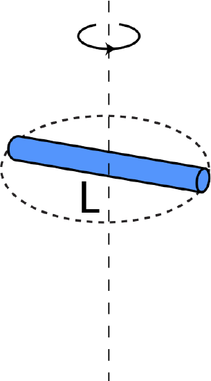
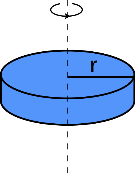
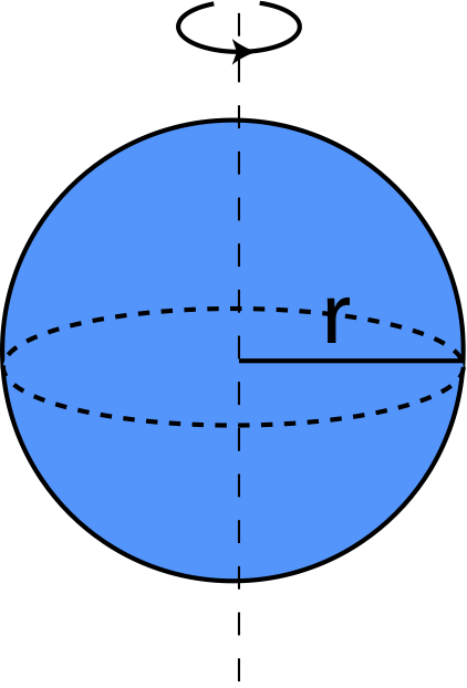
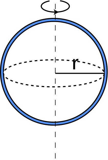
    We will not go into deriving rotational inertia for different objects, but the table below gives the rotational inertia of several simple geometric shapes, as calculated in the limit of infinitesimal increments of mass using this equation. All of there geometric shapes have uniform mass.

    Object Rotational Inertia Illustration
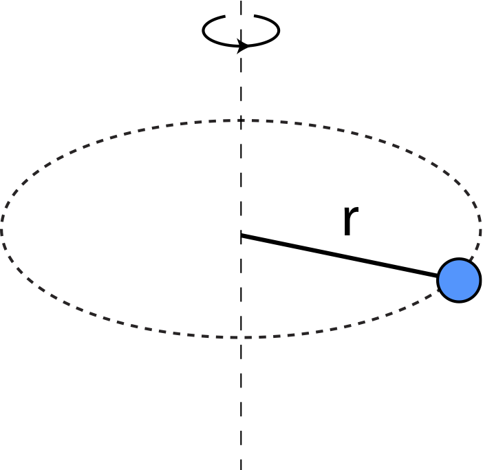
    Point mass \(m\) moving in radius \(r\) \(I=mr^2\) I-point.png
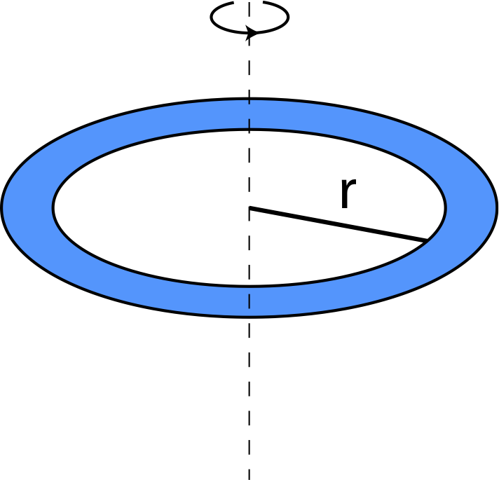
    Thin ring of mass \(m\) and radius \(r\) rotating about center \(I=mr^2\) I-ring.png
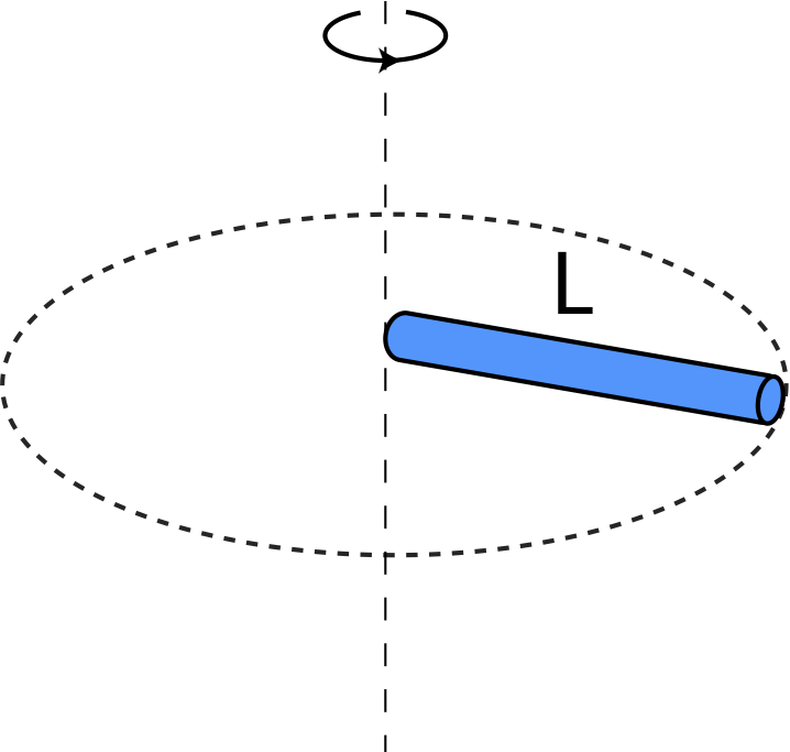
    Thin rod of mass \(m\) and length \(L\) rotating about one end perpendicular to the rod \(I=\frac{1}{3}mL^2\) I-rod-end.png
    Thin rod of mass \(m\) and length \(L\) rotating about its center perpendicular to the rod \(I=\frac{1}{12}mL^2\) I-rod-center.png
    Disk of mass \(m\) radius \(r\) rotating about an axis perpendicular to disk though the center \(I=\frac{1}{2}mr^2\) I-disk.png
    Sphere of mass \(m\) and radius \(r\) rotating about an axis thorough the center \(I=\frac{2}{5}mr^2\) I-sphere.png
    Thin hollow spherical shell of mass \(m\) and radius \(r\) rotating about an axis through the center \(I=\frac{2}{3}mr^2\) I-sphere-shell.png

    As seen from the formulas in the table, objects with the same mass can have very different rotational inertias, depending on how the mass is distributed with respect to the axis of rotation. For example, when the mass of a sphere is concentrated at its radius (as for the spherical shell), its rotational inertia is greater than for the sphere of the same radius and mass but with the mass uniformly distributed from the center (solid sphere). This is consistent with Equation \ref{Ipoint} which shows that rotational inertia increases as mass gets further from the rotational axis.

    The rotational inertia of a composite object is the sum of the rotational inertias of each component, all calculated about the same axis.

    \[ I_{total} = I_1 + I_2 + I_3 + \dots \]

    So for a ring and a disk stacked upon each other and rotating about the symmetry axis of both, the rotational inertia is:

    \[ I_{total} = I_{ring} + I_{disk} \]


    This page titled 6.5: Rotational Inertia is shared under a CC BY 4.0 license and was authored, remixed, and/or curated by Dina Zhabinskaya.

    • Was this article helpful?