
17.4: Determination of the Elements of the True Orbit


- Last updated
- Mar 5, 2022
- Save as PDF

( \newcommand{\kernel}{\mathrm{null}\,}\)
I am assuming at this stage that we have used all the observations plus Kepler’s second law and have determined the apparent orbit well, and can write it in the form
ax2+2hxy+by2+2gx+2fy+c=0.
[The coefficients a and b here, and e in Equation 17.4.3, do not, of course, mean the semi major axis a, the semi minor axis b and eeccentricity e of the true ellipse. It is thought that the reader will be unlikely confused by this, but I have nevertheless used slightly different fonts for them.]
The origin of coordinates here is the primary star, which, although it is at the focus of the true ellipse, is not at the focus of the apparent ellipse. The x-axis points west (to the right) and the y-axis points north (upwards), and position angle θ (measured counterclockwise from north) is given by tanθ=−x/y. Our task is now to find the elements of the true orbit.
During the analysis we are going to be obliged, on more than one occasion, to determine the coordinates of the points where a straight line y=mx+d intersects the ellipse, so it will be worth while to prepare for that now and write a quick program for doing it instantly. The x-coordinates of these points are given by solution of a+2hm+bm2)x2+(2hd+2bmd+2g+2fm)x+bd2+2fd+c=0, 17.4.2 and the y-coordinates are given by solution of the Equation (b+2hn+an2)y2+(2he+2ane+2f+2gn)y+ae2+2ge+c=0, 17.4.3 where n=/1m and e=−d/m. If m is positive the larger solution for y corresponds to the larger solution for x; If m is negative the larger solution for y corresponds to the smaller solution for x.
If the line passes through F, so that d=0, these Equations reduce to
(a+2hm+bm2)x2+(2g+2fm)x+c=0,
and (b+2hn+an2)y2+(2f+2gn)y+c=0.
In figure XVII.3 I draw the true ellipse in the plane of the orbit. F is the primary star at a focus of the true ellipse. C is the centre of the ellipse. I have drawn also the auxiliary circle, the major axis (with periastron P at one end and apastron A at the other end), the latus rectum MN through F and the semi minor axis CK. The ratio FC/PC is the eccentricity e of the true ellipse, and the ratio of minor axis to major axis is √1−e2. This is also the ratio of any ordinate on the auxiliary circle to the corresponding ordinate on the ellipse. Thus I have extended the latus rectum and the semi minor axis by the reciprocal of this factor to meet the auxiliary circle in M′, N′ and K′.
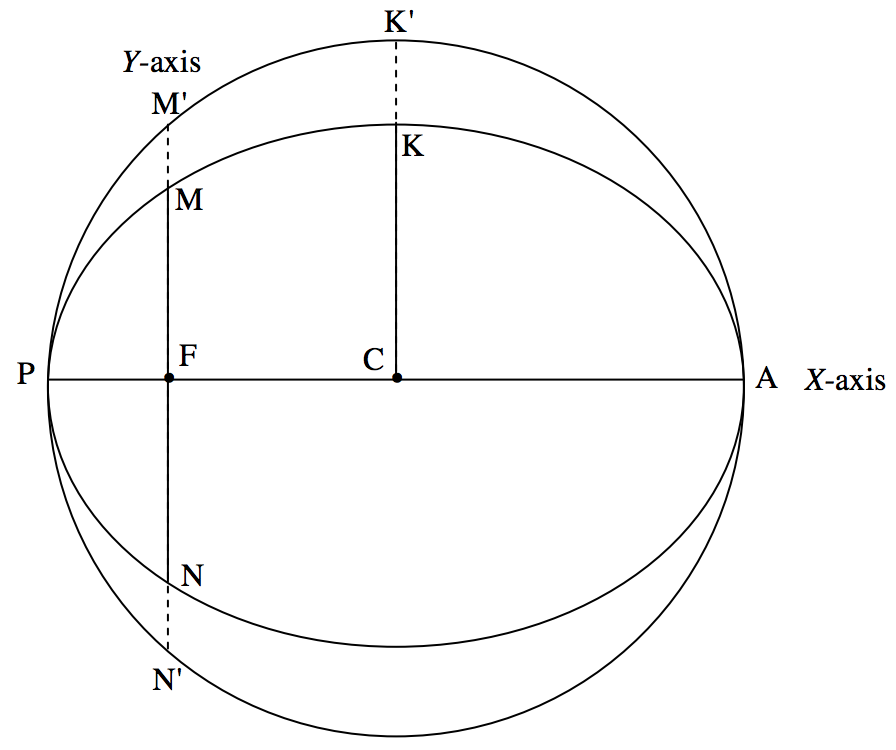
FIGURE 17.3
Now, in figure XVII.4, we are going to look at the same thing as seen projected on the plane of the sky.
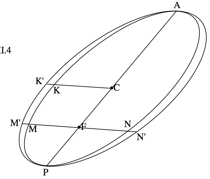
FIGURE XVII.4
The true ellipse has become the apparent ellipse, and the auxiliary circle has become the auxiliary ellipse. At the start of the analysis, we know only the apparent ellipse, which is given by Equation 17.4.1, and the position of the focus F, which is at the origin of coordinates, (0 , 0). F is not at a focus of the apparent ellipse, but C is at the centre of the apparent ellipse.
From section 2.7, we can find the coordinates (ˉx,ˉy) of the centre C. These are (ˉg/ˉc, ˉf/ˉc), where the bar denotes the cofactor in the determinant of coefficients. Thus the slope of the line FC, which is a portion of the true major axis, is ˉf/ˉg. We can now write the Equation of the true major axis in the form y=mx hence, by use of Equations 17.4.4 and 5, we can determine the coordinates of periastron P and apastron A. We can now find the distances FC and PC; and the ratio FC/PC, which has not changed in projection, is the eccentricity e of the true ellipse.
Thus e has been determined.
Our next step is going to be to find the slope of the projected latus rectum MN and the projected semi minor axis CK, which is, of course, parallel to the latus rectum. If the Equation to the projected latus rectum is y=mx, we can find the x-coordinates of M and N by use of Equation 17.4.4. But if MN is a latus rectum, it is of course bisected by the major axis and therefore the length FM and FN are equal. That is to say that the two solutions of Equation 17.4.4 are equal in magnitude and opposite in sign, which in turn implies that the coefficient of x is zero. Thus the slope of the latus rectum (and of the minor axis) is −g/f.
(It is remarked in passing that the projected major and minor axes are conjugate diameters of the apparent ellipse, with slopes ˉf/ˉg and −g/f respectively.)
Now that we have determined the slope of the projected latus rectum, we can easily calculate the coordinates of M and N by solution of Equations 17.4.4 and 17.4.5. Further, CK has the same slope and passes through C, whose coordinates we know, so it is easy to write the Equation to the projected minor axis in the form y=mx+d (d is ˉy−mˉx ), and then solve Equations 17.4.2 and 17.4.3 to find the coordinates of K.
Now we want to extend FM, FN, CK to M′, N′ and K′. For M′ and N′ this is done and simply by replacing x and y by kx and ky, where k is the factor 1/√1−e2. For K′, it is done by replacing x and y by ˉx+k(x−ˉx) and ˉy+k(y−ˉy) respectively.
We now have five points, P, A, M′, N′ and K′, whose coordinates are known and which are on the auxiliary ellipse. This is enough for us to determine the Equation to the auxiliary ellipse in the form of Equation 17.4.1. A quick method of doing this is described in section 2.8 of Chapter 2.
The slopes of the major and minor axis of the auxiliary ellipse (written in the form of Equation 17.4.1) are given by
tan2θ=2ha−b.
This Equation has two solutions for θ, differing by 90∘, the tangents of these being the slopes of the major and minor axes of the auxiliary ellipse. Now that we know these slopes, we can write the Equation to these axes in the form y=mx+d (d is ˉy−mˉx) and so we can determine where the axes cut the auxiliary ellipse and hence we can determine the lengths of the both axes of the auxiliary ellipse.
This has been hard work so far, but we are just about to make real progress. The major axis of the auxiliary ellipse is the only diameter of the auxiliary circle that has not been foreshortened by projection, and therefore it is equal to the diameter of the auxiliary circle, and hence the major axis of the auxiliary ellipse is also equal to the major axis of the true ellipse.
Thus a has been determined.
The ratio of the lengths of the minor to major axes of the auxiliary ellipse is equal to the amount by which the auxiliary circle has been flattened by projection. That is, the ratio of the lengths of the axes is equal to |cosi|. Since the lengths of the axes are essentially positive, we obtain only |cosi|, not cosi itself. However, by our definition of i, it lies between 0∘ and 180∘ and is less than or greater than 90∘ according to whether the position angle of the secondary component is increasing or decreasing with time. For example, if |cosi|=12, i is 60∘ or 120∘, to be distinguished by the sense of motion of the secondary component.
The line of nodes passes through F and is parallel to the major axis of the auxiliary ellipse. This indeed is the reason why the major axis of the auxiliary ellipse was unchanged from its original diameter of the auxiliary circle. We therefore already know the slope of the line of nodes and hence we know the position angle of the first node.
Thus Ω has been determined.
In figure XVII.5 I have added the line of nodes, parallel to the (not drawn) major axis of the auxiliary ellipse. I have used the symbols N and N′ for the first and second nodes, but we do not know (and cannot know without further information) which of these is ascending and which is descending.
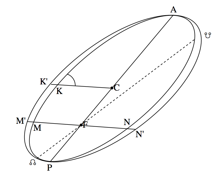
FIGURE XVII.5