
17.3: Torque
- Page ID
- 24531
\( \newcommand{\vecs}[1]{\overset { \scriptstyle \rightharpoonup} {\mathbf{#1}} } \)
\( \newcommand{\vecd}[1]{\overset{-\!-\!\rightharpoonup}{\vphantom{a}\smash {#1}}} \)
\( \newcommand{\dsum}{\displaystyle\sum\limits} \)
\( \newcommand{\dint}{\displaystyle\int\limits} \)
\( \newcommand{\dlim}{\displaystyle\lim\limits} \)
\( \newcommand{\id}{\mathrm{id}}\) \( \newcommand{\Span}{\mathrm{span}}\)
( \newcommand{\kernel}{\mathrm{null}\,}\) \( \newcommand{\range}{\mathrm{range}\,}\)
\( \newcommand{\RealPart}{\mathrm{Re}}\) \( \newcommand{\ImaginaryPart}{\mathrm{Im}}\)
\( \newcommand{\Argument}{\mathrm{Arg}}\) \( \newcommand{\norm}[1]{\| #1 \|}\)
\( \newcommand{\inner}[2]{\langle #1, #2 \rangle}\)
\( \newcommand{\Span}{\mathrm{span}}\)
\( \newcommand{\id}{\mathrm{id}}\)
\( \newcommand{\Span}{\mathrm{span}}\)
\( \newcommand{\kernel}{\mathrm{null}\,}\)
\( \newcommand{\range}{\mathrm{range}\,}\)
\( \newcommand{\RealPart}{\mathrm{Re}}\)
\( \newcommand{\ImaginaryPart}{\mathrm{Im}}\)
\( \newcommand{\Argument}{\mathrm{Arg}}\)
\( \newcommand{\norm}[1]{\| #1 \|}\)
\( \newcommand{\inner}[2]{\langle #1, #2 \rangle}\)
\( \newcommand{\Span}{\mathrm{span}}\) \( \newcommand{\AA}{\unicode[.8,0]{x212B}}\)
\( \newcommand{\vectorA}[1]{\vec{#1}} % arrow\)
\( \newcommand{\vectorAt}[1]{\vec{\text{#1}}} % arrow\)
\( \newcommand{\vectorB}[1]{\overset { \scriptstyle \rightharpoonup} {\mathbf{#1}} } \)
\( \newcommand{\vectorC}[1]{\textbf{#1}} \)
\( \newcommand{\vectorD}[1]{\overrightarrow{#1}} \)
\( \newcommand{\vectorDt}[1]{\overrightarrow{\text{#1}}} \)
\( \newcommand{\vectE}[1]{\overset{-\!-\!\rightharpoonup}{\vphantom{a}\smash{\mathbf {#1}}}} \)
\( \newcommand{\vecs}[1]{\overset { \scriptstyle \rightharpoonup} {\mathbf{#1}} } \)
\(\newcommand{\longvect}{\overrightarrow}\)
\( \newcommand{\vecd}[1]{\overset{-\!-\!\rightharpoonup}{\vphantom{a}\smash {#1}}} \)
\(\newcommand{\avec}{\mathbf a}\) \(\newcommand{\bvec}{\mathbf b}\) \(\newcommand{\cvec}{\mathbf c}\) \(\newcommand{\dvec}{\mathbf d}\) \(\newcommand{\dtil}{\widetilde{\mathbf d}}\) \(\newcommand{\evec}{\mathbf e}\) \(\newcommand{\fvec}{\mathbf f}\) \(\newcommand{\nvec}{\mathbf n}\) \(\newcommand{\pvec}{\mathbf p}\) \(\newcommand{\qvec}{\mathbf q}\) \(\newcommand{\svec}{\mathbf s}\) \(\newcommand{\tvec}{\mathbf t}\) \(\newcommand{\uvec}{\mathbf u}\) \(\newcommand{\vvec}{\mathbf v}\) \(\newcommand{\wvec}{\mathbf w}\) \(\newcommand{\xvec}{\mathbf x}\) \(\newcommand{\yvec}{\mathbf y}\) \(\newcommand{\zvec}{\mathbf z}\) \(\newcommand{\rvec}{\mathbf r}\) \(\newcommand{\mvec}{\mathbf m}\) \(\newcommand{\zerovec}{\mathbf 0}\) \(\newcommand{\onevec}{\mathbf 1}\) \(\newcommand{\real}{\mathbb R}\) \(\newcommand{\twovec}[2]{\left[\begin{array}{r}#1 \\ #2 \end{array}\right]}\) \(\newcommand{\ctwovec}[2]{\left[\begin{array}{c}#1 \\ #2 \end{array}\right]}\) \(\newcommand{\threevec}[3]{\left[\begin{array}{r}#1 \\ #2 \\ #3 \end{array}\right]}\) \(\newcommand{\cthreevec}[3]{\left[\begin{array}{c}#1 \\ #2 \\ #3 \end{array}\right]}\) \(\newcommand{\fourvec}[4]{\left[\begin{array}{r}#1 \\ #2 \\ #3 \\ #4 \end{array}\right]}\) \(\newcommand{\cfourvec}[4]{\left[\begin{array}{c}#1 \\ #2 \\ #3 \\ #4 \end{array}\right]}\) \(\newcommand{\fivevec}[5]{\left[\begin{array}{r}#1 \\ #2 \\ #3 \\ #4 \\ #5 \\ \end{array}\right]}\) \(\newcommand{\cfivevec}[5]{\left[\begin{array}{c}#1 \\ #2 \\ #3 \\ #4 \\ #5 \\ \end{array}\right]}\) \(\newcommand{\mattwo}[4]{\left[\begin{array}{rr}#1 \amp #2 \\ #3 \amp #4 \\ \end{array}\right]}\) \(\newcommand{\laspan}[1]{\text{Span}\{#1\}}\) \(\newcommand{\bcal}{\cal B}\) \(\newcommand{\ccal}{\cal C}\) \(\newcommand{\scal}{\cal S}\) \(\newcommand{\wcal}{\cal W}\) \(\newcommand{\ecal}{\cal E}\) \(\newcommand{\coords}[2]{\left\{#1\right\}_{#2}}\) \(\newcommand{\gray}[1]{\color{gray}{#1}}\) \(\newcommand{\lgray}[1]{\color{lightgray}{#1}}\) \(\newcommand{\rank}{\operatorname{rank}}\) \(\newcommand{\row}{\text{Row}}\) \(\newcommand{\col}{\text{Col}}\) \(\renewcommand{\row}{\text{Row}}\) \(\newcommand{\nul}{\text{Nul}}\) \(\newcommand{\var}{\text{Var}}\) \(\newcommand{\corr}{\text{corr}}\) \(\newcommand{\len}[1]{\left|#1\right|}\) \(\newcommand{\bbar}{\overline{\bvec}}\) \(\newcommand{\bhat}{\widehat{\bvec}}\) \(\newcommand{\bperp}{\bvec^\perp}\) \(\newcommand{\xhat}{\widehat{\xvec}}\) \(\newcommand{\vhat}{\widehat{\vvec}}\) \(\newcommand{\uhat}{\widehat{\uvec}}\) \(\newcommand{\what}{\widehat{\wvec}}\) \(\newcommand{\Sighat}{\widehat{\Sigma}}\) \(\newcommand{\lt}{<}\) \(\newcommand{\gt}{>}\) \(\newcommand{\amp}{&}\) \(\definecolor{fillinmathshade}{gray}{0.9}\)Definition of Torque about a Point
In order to understand the dynamics of a rotating rigid body we will introduce a new quantity, the torque. Let a force \(\overrightarrow{\mathbf{F}}_{P}\) with magnitude \(F=\left|\overrightarrow{\mathbf{F}}_{P}\right|\) act at a point P. Let \(\overrightarrow{\mathbf{r}}_{S, P}\) be the vector from the point \(S\) to a point P , with magnitude \(r=\left|\overrightarrow{\mathbf{r}}_{S, P}\right|\). The angle between the vectors \(\overrightarrow{\mathbf{r}}_{S, P}\) and \(\overrightarrow{\mathbf{F}}_{p}\) is θ with \([0 \leq \theta \leq \pi]\) (Figure 17.9).
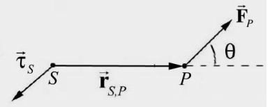
The torque about a point \(S\) due to force \(\overrightarrow{\mathbf{F}}_{P}\) acting at P , is defined by
\[\vec{\tau}_{S}=\overrightarrow{\mathbf{r}}_{S, P} \times \overrightarrow{\mathbf{F}}_{P} \nonumber \]
The magnitude of the torque about a point \(S\) due to force \(\overrightarrow{\mathbf{F}}_{P}\) acting at P , is given by
\[\tau_{S} \equiv\left|\vec{\tau}_{S}\right|=r F \sin \theta \nonumber \]
The SI units for torque are [N⋅m]. The direction of the torque is perpendicular to the plane formed by the vectors \(\overrightarrow{\mathbf{r}}_{S, P}\) and \(\overrightarrow{\mathbf{F}}_{P} \quad \text { (for } \left.[0<\theta<\pi]\right)\), and by definition points in the direction of the unit normal vector to the plane \(\hat{\mathbf{n}}_{R H R}\) as shown in Figure 17.10.
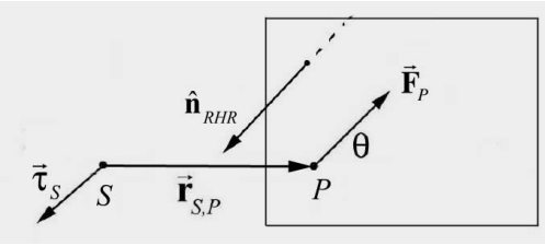
Figure 17.11 shows the two different ways of defining height and base for a parallelogram defined by the vectors \(\overrightarrow{\mathbf{r}}_{S, P} \text { and } \overrightarrow{mathbf{F}}_{P}\).
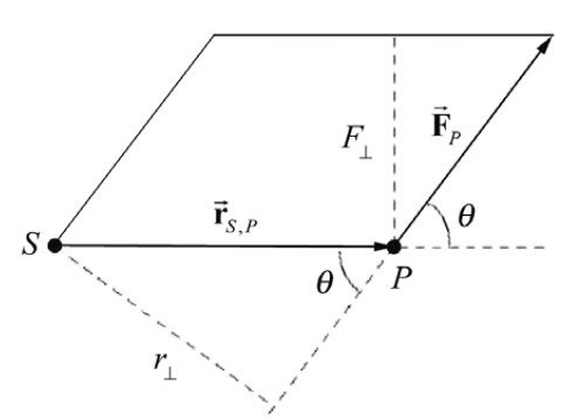
Let \(r_{\perp}=r \sin \theta\) and \(F_{\perp}=F \sin \theta\) be the component of the force \(\overrightarrow{\mathbf{F}}_{P}\) that is perpendicular to the line passing from the point \(S\) to P . (Recall the angle θ has a range of values \(0 \leq \theta \leq \pi\) so both \(r_{\perp} \geq 0 \text { and } F_{\perp} \geq 0\). Then the area of the parallelogram defined by \(\overrightarrow{\mathbf{r}}_{S, P}\) and \(\overrightarrow{\mathbf{F}}_{P}\) is given by
\[\text { Area }=\tau_{S}=r_{\perp} F=r F_{\perp}=r F \sin \theta \nonumber \]
We can interpret the quantity \(r_{\perp}\) as follows.
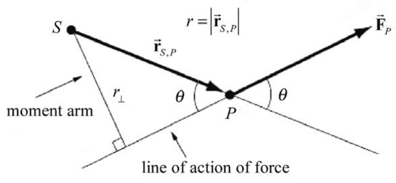
We begin by drawing the line of action of the force \(\overrightarrow{\mathbf{F}}_{P}\). This is a straight line passing through P , parallel to the direction of the force \(\overrightarrow{\mathbf{F}}_{P}\). Draw a perpendicular to this line of action that passes through the point \(S\) (Figure 17.12). The length of this perpendicular, \(r_{\perp}=r \sin \theta\), is called the moment arm about the point \(S\) of the force \(\overrightarrow{\mathbf{F}}_{P}\).
You should keep in mind three important properties of torque:
1. The torque is zero if the vectors \(\overrightarrow{\mathbf{r}}_{S, P}\) and \(\overrightarrow{\mathbf{F}}_{P}\) are parallel (θ = 0) or anti-parallel \((\theta=\pi)\).
2. Torque is a vector whose direction and magnitude depend on the choice of a point \(S\) about which the torque is calculated.
3. The direction of torque is perpendicular to the plane formed by the two vectors, \(\overrightarrow{\mathbf{F}}_{P}\) and \(r=\left|\overrightarrow{\mathbf{r}}_{S, P}\right|\) (the vector from the point \(S\) to a point P ).
Alternative Approach to Assigning a Sign Convention for Torque
In the case where all of the forces \(\overrightarrow{\mathbf{F}}_{i}\) and position vectors \(\overrightarrow{\mathbf{r}}_{i, P}\) are coplanar (or zero), we can, instead of referring to the direction of torque, assign a purely algebraic positive or negative sign to torque according to the following convention. We note that the arc in Figure 17.13a circles in counterclockwise direction. (Figures 17.13a and 17.13b use the simplifying assumption, for the purpose of the figure only, that the two vectors in question, \(\overrightarrow{\mathbf{F}}_{P}\) and \(\overrightarrow{\mathbf{r}}_{S, P}\) are perpendicular. The point \(S\) about which torques are calculated is not shown.)
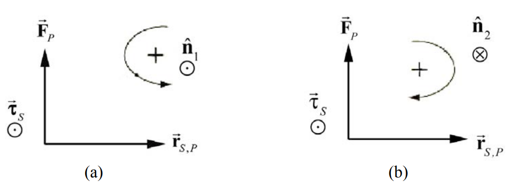
We can associate with this counterclockwise orientation a unit normal vector \(\hat{\mathbf{n}}\) according to the right-hand rule: curl your right hand fingers in the counterclockwise direction and your right thumb will then point in the \(\hat{\mathbf{n}}_{1}\) direction (Figure 17.13a). The arc in Figure 17.13b circles in the clockwise direction, and we associate this orientation with the unit normal \(\hat{\mathbf{n}}_{2}\).
It’s important to note that the terms “clockwise” and “counterclockwise” might be different for different observers. For instance, if the plane containing \(\overrightarrow{\mathbf{F}}_{P} \text { and } \overrightarrow{\mathbf{r}}_{S, P}\) is , horizontal, an observer above the plane and an observer below the plane would disagree on the two terms. For a vertical plane, the directions that two observers on opposite sides of the plane would be mirror images of each other, and so again the observers would disagree.
1. Suppose we choose counterclockwise as positive. Then we assign a positive sign for the component of the torque when the torque is in the same direction as the unit normal \(\hat{\mathbf{n}}_{1}, \text { i.e. } \vec{\tau}_{S}=\overrightarrow{\mathbf{r}}_{S, P} \times \overrightarrow{\mathbf{F}}_{P}=+\left|\overrightarrow{\mathbf{r}}_{S, P}\right|\left|\overrightarrow{\mathbf{F}}_{P}\right| \hat{\mathbf{n}}_{l}\) (Figure 17.13a).
2. Suppose we choose clockwise as positive. Then we assign a negative sign for the component of the torque in Figure 17.13b because the torque is directed opposite to the unit normal \(\hat{\mathbf{n}}_{2}, \text { i.e. } \vec{\tau}_{S}=\overrightarrow{\mathbf{r}}_{S, P} \times \overrightarrow{\mathbf{F}}_{P}=-\left|\overrightarrow{\mathbf{r}}_{S, P}\right| \overrightarrow{\mathbf{F}}_{P} \mid \hat{\mathbf{n}}_{2}\).
Example 17.6 Torque and Vector Product
Consider two vectors \(\overrightarrow{\mathbf{r}}_{P, F}=x \hat{\mathbf{i}}\) with \(x>0\) and \(\overrightarrow{\mathbf{F}}=F_{x} \hat{\mathbf{i}}+F_{z} \hat{\mathbf{k}}\) with \(F_{x}>0 \text { and } F_{z}>0\) Calculate the torque \(\overrightarrow{\mathbf{r}}_{P, F} \times \overrightarrow{\mathbf{F}}\).
Solution: We calculate the vector product noting that in a right handed choice of unit vectors, \(\hat{\mathbf{i}} \times \hat{\mathbf{i}}=\overrightarrow{\mathbf{0}} \text { and } \hat{\mathbf{i}} \times \hat{\mathbf{k}}=-\hat{\mathbf{j}}\)
\[\overrightarrow{\mathbf{r}}_{P, F} \times \overrightarrow{\mathbf{F}}=x \hat{\mathbf{i}} \times\left(F_{x} \hat{\mathbf{i}}+F_{z} \hat{\mathbf{k}}\right)=\left(x \hat{\mathbf{i}} \times F_{x} \hat{\mathbf{i}}\right)+\left(x \hat{\mathbf{i}} \times F_{z} \hat{\mathbf{k}}\right)=-x F_{z} \hat{\mathbf{j}} \nonumber \]
Because \(x>0 \text { and } F_{z}>0\) the direction of the vector product is in the negative y - direction.
Example 17.7 Calculating Torque
In Figure 17.14, a force of magnitude F is applied to one end of a lever of length L. What is the magnitude and direction of the torque about the point S?
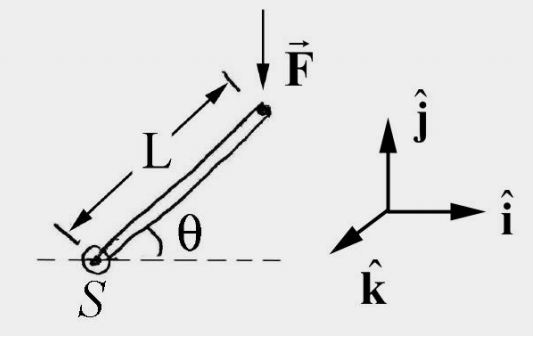
Solution: Choose units vectors such that \(\hat{\mathbf{i}} \times \hat{\mathbf{j}}=\hat{\mathbf{k}}\), with \(\hat{\mathbf{i}}\) pointing to the right and \(\hat{\mathbf{j}}\) pointing up (Figure 17.15). The torque about the point \(S\) is given by \(\vec{\tau}_{S}=\overrightarrow{\mathbf{r}}_{S, F} \times \overrightarrow{\mathbf{F}}\) where \(\overrightarrow{\mathbf{r}}_{S F}=L \cos \theta \hat{\mathbf{i}}+L \sin \theta \hat{\mathbf{j}}\) and \(\overrightarrow{\mathbf{F}}=-F \hat{\mathbf{j}}\) then
\[\vec{\tau}_{S}=(L \cos \theta \hat{\mathbf{i}}+L \sin \theta \hat{\mathbf{j}}) \times-F \hat{\mathbf{j}}=-F L \cos \theta \hat{\mathbf{k}} \nonumber \]
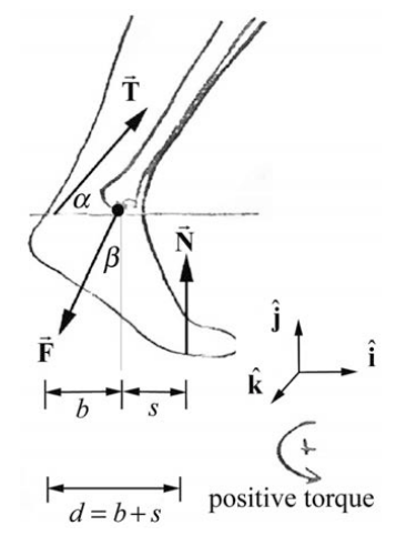
Example 17.8 Torque and the Ankle
A person of mass m is crouching with their weight evenly distributed on both tiptoes. The free-body force diagram on the skeletal part of the foot is shown in Figure 17.16. The normal force \(\overrightarrow{\mathbf{N}}\) acts at the contact point between the foot and the ground. In this position, the tibia acts on the foot at the point \(S\) with a force \(\overrightarrow{\mathbf{F}}\) of an unknown magnitude \(F=|\overrightarrow{\mathbf{F}}|\) and makes an unknown angle \(\beta\) with the vertical. This force acts on the ankle a horizontal distance s from the point where the foot contacts the floor. The Achilles tendon also acts on the foot and is under considerable tension with magnitude \(T \equiv|\overrightarrow{\mathbf{T}}|\) and acts at an angle α with the horizontal as shown in the figure. The tendon acts on the ankle a horizontal distance b from the point \(S\) where the tibia acts on the foot. You may ignore the weight of the foot. Let g be the gravitational constant. Compute the torque about the point \(S\) due to (a) the tendon force on the foot; (b) the force of the tibia on the foot; (c) the normal force of the floor on the foot.
Solution: (a) We shall first calculate the torque due to the force of the Achilles tendon on the ankle. The tendon force has the vector decomposition \(\overrightarrow{\mathbf{T}}=T \cos \alpha \hat{\mathbf{i}}+T \sin \alpha \hat{\mathbf{j}}\)
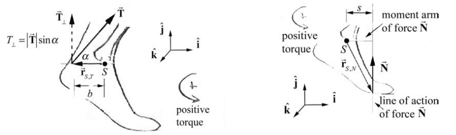
The vector from the point \(S\) to the point of action of the force is given by \(\overrightarrow{\mathbf{r}}_{S, T}=-b \hat{\mathbf{i}}\) (Figure 17.17). Therefore the torque due to the force of the tendon \(\overrightarrow{\mathbf{T}}\) on the ankle about the point \(S\) is then
\[\vec{\tau}_{S, T}=\overrightarrow{\mathbf{r}}_{S, T} \times \overrightarrow{\mathbf{T}}=-b \hat{\mathbf{i}} \times(T \cos \alpha \hat{\mathbf{i}}+T \sin \alpha \hat{\mathbf{j}})=-b T \sin \alpha \hat{\mathbf{k}} \nonumber \]
(b) The torque diagram for the normal force is shown in Figure 17.18. The vector from the point \(S\) to the point where the normal force acts on the foot is given by \(\overrightarrow{\mathbf{r}}_{S, N}=(\hat{\mathbf{i}}-h \hat{\mathbf{j}})\). Because the weight is evenly distributed on the two feet, the normal force on one foot is equal to half the weight, or \(N=(1 / 2) m g\). The normal force is therefore given by \(\overrightarrow{\mathbf{N}}=N \hat{\mathbf{j}}=(1 / 2) m g \hat{\mathbf{j}}\). Therefore the torque of the normal force about the point \(S\) is
\[\vec{\tau}_{S, N}=\overrightarrow{\mathbf{r}}_{S, N} \times N \hat{\mathbf{j}}=((\hat{\mathbf{i}}-h \hat{\mathbf{j}}) \times N \hat{\mathbf{j}}=s N \hat{\mathbf{k}}=(1 / 2) s m g \hat{\mathbf{k}} \nonumber \]
(c) The force \(\overrightarrow{\mathbf{F}}\) that the tibia exerts on the ankle will make no contribution to the torque about this point \(S\) since the tibia force acts at the point \(S\) and therefore the vector \(\overrightarrow{\mathbf{r}}_{S, F}=\overrightarrow{\mathbf{0}}\).