
10.9: Induced Voltage and Magnetic Flux
- Page ID
- 46226

Learning Objectives
- Describe methods to produce an induced voltage with a magnetic field or magnet and a loop of wire.
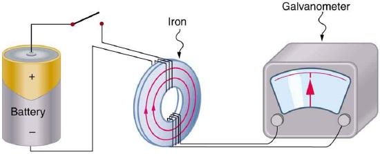
The apparatus used by Faraday to demonstrate that magnetic fields can create currents is illustrated in Figure \(\PageIndex{1}\). When the switch is closed, a magnetic field is produced in the coil on the top part of the iron ring and transmitted to the coil on the bottom part of the ring. The galvanometer is used to detect any current induced in the coil on the bottom. It was found that each time the switch is closed, the galvanometer detects a current in one direction in the coil on the bottom. Each time the switch is opened, the galvanometer detects a current in the opposite direction. Interestingly, if the switch remains closed or open for any length of time, there is no current through the galvanometer. Closing and opening the switch induces the current. It is the change in magnetic field that creates the current in the following way: a changing magnetic field induces an electric field, which results in the induced voltage. When this induced voltage occurs over a conducting path, as in this example, the induced voltage causes a current to flow. As a shorthand, we call the resulting current induced current; the changing magnetic field does not induce the current directly but through the induced voltage and an application of Ohm's law.
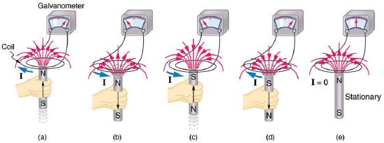
An experiment easily performed and often done in physics labs is illustrated in Figure \(\PageIndex{2}\). A voltage is induced in the coil when a bar magnet is pushed in and out of it. Voltages of opposite signs are produced by motion in opposite directions, and the voltages are also reversed by reversing poles. The same results are produced if the coil is moved rather than the magnet—it is the relative motion that is important. The faster the motion, the greater the voltage, and there is no voltage when the magnet is stationary relative to the coil.
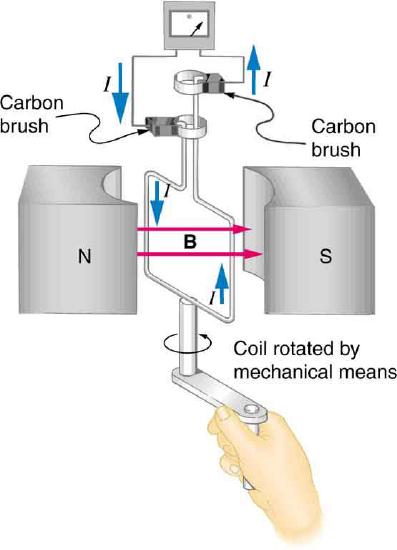
The method of inducing a voltage used in most electric generators is shown in Figure \(\PageIndex{3}\). A coil is rotated in a magnetic field, producing an alternating voltage (and current), which depends on rotation rate and other factors that will be explored in later sections. Note that the generator is remarkably similar in construction to a motor.
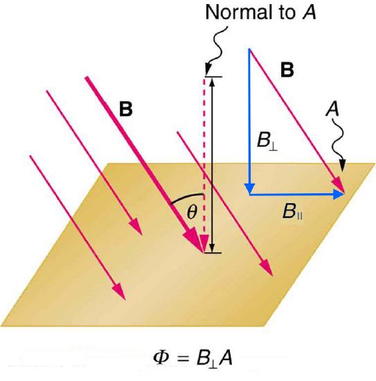
So we see that changing the magnitude or direction of a magnetic field produces a voltage. Experiments revealed that there is a crucial quantity called the magnetic flux, \(\Phi\) , given by
\[\Phi=B_{\perp} A, \nonumber \]
where \(B\) is the magnetic field strength over an area \(A\), at an angle \(\theta\) with the perpendicular to the area as shown in Figure \(\PageIndex{4}\). Any change in magnetic flux \(\Phi\) induces a voltage. This process is defined to be electromagnetic induction. Units of magnetic flux \(\Phi\) are \(\mathrm{T} \cdot \mathrm{m}^{2}\).
All induction, including the examples given so far, arises from some change in magnetic flux \(\Phi\). For example, Faraday changed \(B\) and hence \(\Phi\) when opening and closing the switch in his apparatus (shown in Figure \(\PageIndex{1}\)). This is also true for the bar magnet and coil shown in Figure \(\PageIndex{2}\). When rotating the coil of a generator, the angle \(\theta\) and, hence, \(\Phi\) is changed. Just how great a voltage and what direction it takes depend on the change in \(\Phi\) and how rapidly the change is made, as examined in the next section.
Section Summary
- The crucial quantity in induction is magnetic flux \(\Phi\), defined to be \(\Phi=B_{\perp} A\), where \(B_{\perp}\) is the magnetic field strength perpendicular to the area \(A\).
- Units of magnetic flux \(\Phi\) are \(\mathrm{T} \cdot \mathrm{m}^{2}\).
- Any change in magnetic flux \(\Phi\) induces a voltage—the process is defined to be electromagnetic induction.
Glossary
- induced current
- the current created by a changing magnetic field through voltage induced over a conducting path
- magnetic flux
- the amount of magnetic field going through a particular area, calculated with \(\Phi=B_{\perp} A\), where \(B_{\perp}\) is the magnetic field strength perpendicular to the area \(A\)
- electromagnetic induction
- the process of inducing a voltage with a change in magnetic flux