
13.11: Chapter- 11


- Last updated
- Jun 21, 2021
- Save as PDF

( \newcommand{\kernel}{\mathrm{null}\,}\)
Problem (11.1).
A strip-line is constructed from a metal strip 1 mm wide (W= 1 mm) separated from a ground plane by an oxide layer whose thickness, D, is 20 µm. The relative dielectric constant of the oxide layer is εr= 8.00, and its relative permeability is µr= 1.00.
(a) What is the velocity of an electromagnetic wave on this line?
(b) What is the characteristic impedance of the strip-line?
(c) A pulse on the line is 10 meters long and corresponds to a constant potential difference of 10 Volts. How much energy is stored in the pulse?
Answer (11.1).
(a) v2=1εμ=c2εr=c28; v= 1.06 x 10⁸ m/sec.
(b) In the dielectric material one finds curlE= iωµ0 H for a wave having a time dependence e−iωt. Therefore
∂EX∂z=iωμ0Hy,
and
Ex=(ωμ0k)Hy where kv=ω.
Thus ExHy=vμ0=133.2 Ohms.
In the strip line the potential is V= ExD, and the current is given by I= WHy. It follows that the characteristic impedance is given by
Z0=VI=ExDHyW=(DW)(133.2)=2.66 ohms.
(c) The electric field in the insulator is EX=VD, so
Ex=1020×10−6=5×10⁵ Volts /m.
Hy=EX133⋅2=3.754×10³ Amps/m.
The energy density stored in the electric field is given by
WE=εE22=εr2ε0E2x=4ε0E2x Joules /m3.
The energy density stored in the magnetic field is given by
WB=μH22=μ0H2Y2 Joules /m3.
But EXHY=C√8μ0 or Hy=√8cμ0Ex
so that WB=4ε0E2x Joules /m3.
The total energy density is W=WE+WB=8ε0E2X.
So W= (8)(8.84 x 10⁻¹²)(25x1010) = 17.86 Joules/m3
The volume which contains this energy density is given by
Vol.=(10)(10−3)(20×10−6)=2×10⁻⁷ m3.
The total energy stored in the pulse is 3.54 x 10⁻⁶ Joules.
Problem (11.2).
The space between the conductors in a co-axial cable is filled with polyethylene which has a relative dielectric constant εr= 2.25. The characteristic impedance of the cable is 50 Ohms. A 10 meter length of cable is used to connect a pulse generator to a load of R Ohms. The incident pulse amplitude is V0.
(a) What is the amplitude of the reflected pulse if the cable is terminated by 50 Ohms?
(b) What is the amplitude of the reflected pulse if the cable is terminated by zero Ohms?
(c) What is the amplitude of the reflected pulse if the cable is terminated by an open circuit?
(d) What is the amplitude of the reflected pulse if the cable is terminated by 100 Ohms?
(e) What is the inductance per meter of cable?
(f) What is the capacitance per meter of cable?
Answer (11.2).
The velocity of a pulse on the cable is v=c√εr=2c3=2.0×10⁸ m/sec, and the characteristic impedance is Z0= 50 Ohms. The reflection coefficient is given by VRV0=r−1r+1, where r=RZ0.
(a) R= 50 Ohms, therefore r=1 and VR= 0.
(b) R= 0 Ohms, therefore r= 0 and VR= - V0.
(c) R= ∞ Ohms, therefore r= ∞ and VR= +V0.
(d) R= 100 Ohms, therefore r= 2 and VRV0=13.
(e) V2=1LC and Z0=√L/C so that
L/C=2500 and LC=14×1016.
Consequently, L2=25004×1016 and L=14 μHenry/m.
C=L2500=100 pF/m.
Problem (11.3).
A typical co-axial cable has a characteristic impedance of 50 Ohms (Zo = 50 Ohms). The dielectric material can be regarded as lossless and εr = 2.25. The cable is connected to a 50 Ohm pulse generator and is terminated by a resistance R Ohms (see the figure).
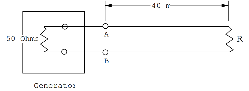
An oscilloscope is connected across AB: its impedance is effectively infinite so that it does not disturb the propagation of pulses on the line. The distance between AB and the end of the line is 40 meters. The generator emits a rectangular pulse whose amplitude is 5 Volts and whose length in time is 10-7 seconds.
(a) What is the velocity of pulses on this cable?
(b) Let R = 0. Make a sketch of the signal measured using the oscilloscope across AB.
(c) Let R = 0. Make a sketch of the signal measured using the oscilloscope connected across the resistor, R.
(d) Let R = 50 Ohms. Make a sketch of the signal measured across AB.
(e) Let R = 50 Ohms. Make a sketch of the signal measured across the resistor, R.
(f) Let R → ∞ (an open circuit). Make a sketch of the signal measured across AB.
(g) Let R → ∞. Make a sketch of the signal measured across the open end of the cable.
Answer (11.3).
(a) For this cable εr = n2 = 9/4 therefore n = 3/2. The velocity of propagation v=cn=2×10⁸ m/sec.
(b) Shorted Cable. At AB one sees the original pulse followed by the reflected pulse after a time delay of 80/v = 4 x 10⁻⁷ seconds (40 m out and 40 m back). The reflected pulse is inverted.
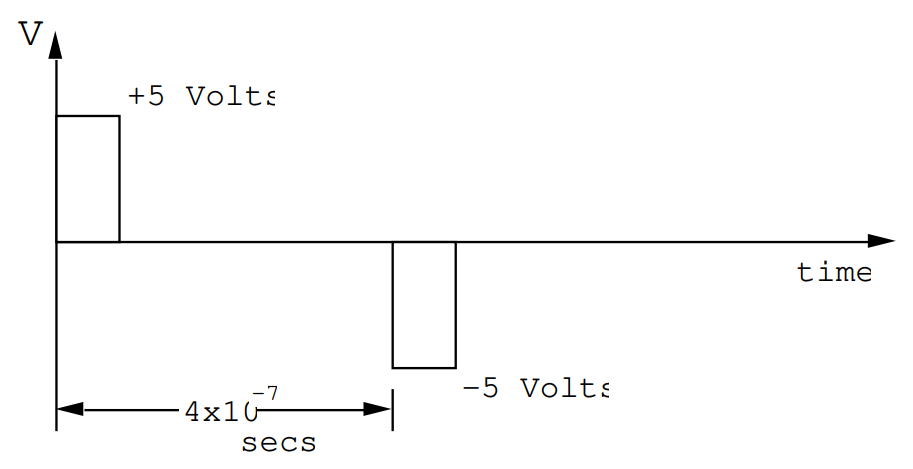
The reflected pulse is absorbed in the generator because the generator impedance is Zo = 50 Ohms.
(c)Shorted Cable. Nothing will be seen across the short at the end of the cable (R = 0).
(d) Cable terminated by Zo = 50 Ohms. One will measure only the initial pulse. There is no reflected pulse.
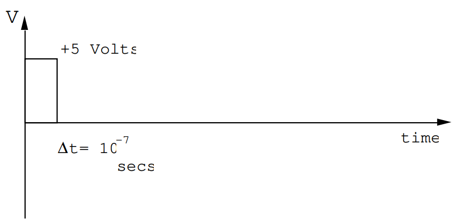
(e) Cable terminated by 50 Ohms. The voltage across the 50 Ohms will just look like the incident pulse but delayed by 40/v = 2 x 10⁻⁷ secs.
(f) Open circuit. At AB one will see the original pulse followed 80/(2 x 108) = 4 x 10⁻⁷ secs. later by a similar pulse. The reflected pulse will then be absorbed in the generator.
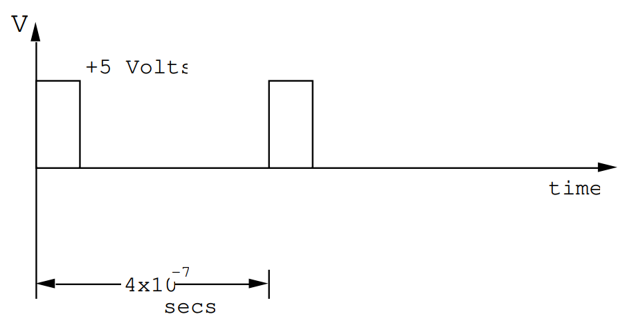
This is a standard technique for generating a delayed pulse.
(g) At the open end of the cable one will measure a single pulse whose amplitude is twice that of the original pulse. (One measures Vo + VR). There will be a time delay of 2 x 10⁻⁷ secs.
Problem (11.4).
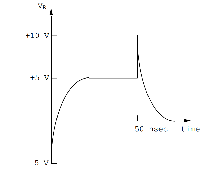
A certain co-axial cable is characterized by a velocity of v= 2.00 x 10⁸ meters/sec., and it has a characteristic impedance of 50 Ohms. The cable is terminated by a capacitor C= 100 pF. A 10 Meter long rectangular pulse whose amplitude is 5 Volts is launched along the cable. Make a sketch of the reflected pulse. Carefully indicate the voltage and time scales; let the reflected pulse reach the observer at t=0. What is the maximum voltage in the reflected pulse?
Answer (11.4).
A 10 m pulse has a time duration of 5 x 10⁻⁸ seconds. The time constant associated with the capacitor is CZ0= 5 x 10⁻⁹ secs., therefore the capacitor will become fully charged during the time that the pulse is applied to it.
(i) Initially the capacitor behaves like a short circuit; the reflected pulse will have an amplitude of -5 Volts. This amplitude decays to +5 Volts as the capacitor becomes fully charged and looks like an open circuit. Note that when fully charged the potential across the capacitor is V0+VR= 10 Volts.
(ii) At the end of the incident pulse the capacitor, which has been charged to +10 Volts, deposits its charge back into the line at a rate determined by C and the characteristic impedance, Z0.
Problem (11.5).
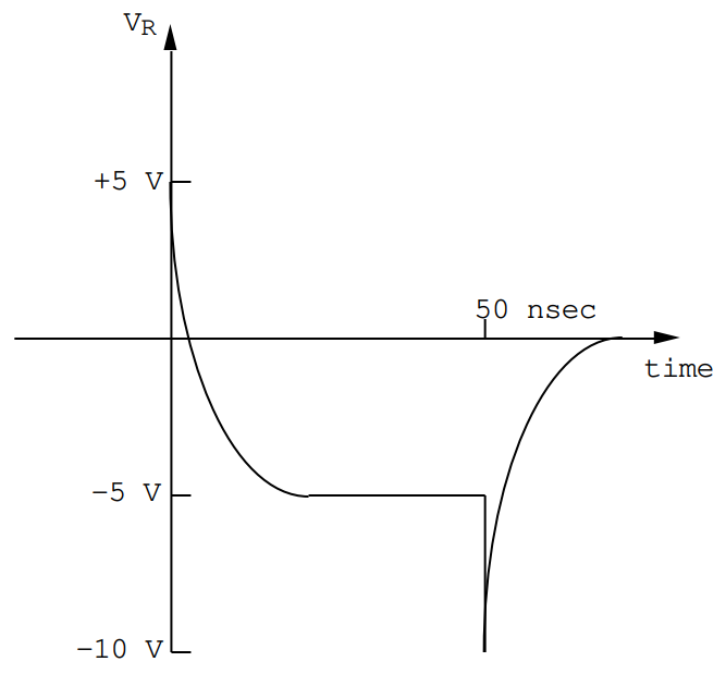
A certain co-axial cable is characterized by a velocity of V= 2.00 x 10⁸ meters/sec., and it has a characteristic impedance of 50 Ohms. The cable is terminated by an inductor L= 0.25 µH. A 10 Meter long rectangular pulse whose amplitude is 5 Volts is launched along the cable. Make a sketch of the reflected pulse. Carefully indicate the voltage and time scales; let the reflected pulse reach the observer at t=0. What is the maximum voltage in the reflected pulse?
Answer (11.5).
The time duration of the pulse is 5 x 10⁻⁸ secs.= 50 nsecs., whereas the time constant associated with the inductor is τ=LZ0=0.5×10⁻⁸ secs. =5 nsecs ; thus the inductor will become fully charged with magnetic energy during the course of the pulse.
(i) At t=0 the inductor looks like an open circuit because it resists a change in the current flowing through it. The reflected pulse will therefore have an amplitude of +5 Volts, equal to the amplitude of the incident pulse. The reflected amplitude will decay with a time constant τ=L/Z0 as the current through the inductor reaches a steady state value. When the current has become constant, the inductor looks like a short circuit and the reflected pulse amplitude is -5 Volts.
(ii) The steady state value of the current through the inductor is just twice the current in the incident pulse, i.e. I0=2V0Z0 Amps, corresponding to a short circuit. Upon termination of the pulse, this current collapses to give an initial voltage
V=LdIdt=−LτI0=−Z0(2V0Z0)=−2V0.
Problem (11.6).
A certain co-axial cable is characterized by a velocity of V= 2.00 x 10⁸ meters/sec., and it has a characteristic impedance of 50 Ohms. A piece of this cable 21 m long is used to connect a 250 MHz oscillator to a load impedance ZL.
(a) What load impedance will be presented to the generator if ZL is a 50 Ohm resistor?
(b) What load impedance will be presented to the generator if ZL is a 1.00 µH inductor?
(c) What load impedance will be presented to the generator if ZL is a 100 pF capacitor?
(d) What impedance will be presented to the generator in the above three cases if the co-axial cable has a length of 20.0 meters?
Answer (11.6).
At 250 MHz and for v= 2.00 x 10⁸ m/sec. the wavelength on the cable is λ=2×1082.5×108=45 meters .
(a) Terminated by the characteristic impedance. The generator looks into 50 Ohms.
(b) At 250 MHz. the impedance of a 1.0 µH inductor is given by ZL= iLω = 1571i Ohms, since ω= 1.57 x 10⁹ radians/sec. ZLZ0=i31.42
2ikl=i4π(21)λ=105iπ
which is equivalent to a phase shift of π. Since the impedance seen by the generator is
ZGZ0=1+b/a1−b/a,
where
ba=(z−1z+1)e−2ikl,
and
z=ZLZ0,
one finds ba=1−i31⋅421+i31⋅42=−0.998−i0.0636.
ZGZ0=1+b/a1−b/a=−i0.0319,
or ZG= -1.59i Ohms. The load appears to the generator like a capacitor with C= 400 pF!
(c) The load impedance is a 100 pF capacitor.
For the capacitor Zc=−icω=−i6.366 Ohms .
z=zLz0=−i0.1273
As before e-2ikl = -1 so that
b/a=1−z1+z=0.9681+i0.2505.
ZGZ0=1+b/a1−b/a=i7.855,
from which ZG=i392.8 Ohms. .
The load appears to the generator like a 0.25 µH inductor.
(d) A 20 m cable contains an integer number of wavelengths, therefore the generator will look into the load impedance exactly as if the cable had zero length.
(a) ZG = 50 Ohms.
(b) ZG = i1571 Ohms (Inductive).
(c) ZG = -i6.37 Ohms.
Problem (11.7).
A co-axial cable is characterized by a characteristic impedance of Zo = 50 Ohms and a velocity of propagation of 2 x 10⁸ m/sec. It is used to connect a 10 Ohm load to a generator. Calculate the impedance as seen from the generator for a cable having the following lengths, L:
(a) L = λ/8
(b) L = λ/4
(c) L = 3λ/8
(d) L = λ/2
(e) Calculate the Voltage Standing Wave Ratio, VSWR.
Answer (11.7).
For a load of ZL = 10 one has a normalized impedance ZL=1050=0.20
∴
(a) \mathrm{L}=\frac{\lambda}{8} \quad \quad \therefore \mathrm{e}^{-2 \mathrm{ikL}} =\mathrm{e}^{-\mathrm{i} 4 \pi \mathrm{L} / \lambda}=\mathrm{e}^{-\mathrm{i} \pi / 2}=-\mathrm{i}
\therefore \Gamma e^{-2 i k L}=\frac{2 i}{3}\nonumber
\therefore \mathrm{z}_{\mathrm{G}}=\frac{1+\Gamma \mathrm{e}^{-2 \mathrm{ikL}}}{1-\Gamma \mathrm{e}^{-2 \mathrm{ikL}}}=\frac{1+2 \mathrm{i} / 3}{1-2 \mathrm{i} / 3}=\frac{3+2 \mathrm{i}}{3-2 \mathrm{i}}=\frac{(3+2 i)(3+2 i)}{9+4}\nonumber
\therefore \quad Z_{G}=\frac{5+12 i}{13}=0.385+0.923 i\nonumber
\therefore Z_{G}=50 Z_{G}=\mathbf{19.23+46.15 \mathrm{i}} \text { Ohms }\nonumber
i.e. a large inductive component
(b) L = λ/4 e-2ikL = e-i4\piL/λ = e-i\pi = -1
\therefore \Gamma \mathrm{e}^{-2 \mathrm{ikL}}=2 / 3 \ (\mathrm{real})
\therefore Z_{G}=\frac{1+2 / 3}{1-2 / 3}=\frac{5 / 3}{1 / 3}=5
∴ ZG = 250 Ohms (purely real and relatively large!).
(c) \mathrm{L}=\frac{3 \lambda}{8} \quad \mathrm{e}^{-2 \mathrm{i} \mathrm{k} \mathrm{L}}=\mathrm{e}^{-\mathrm{i} 4 \pi \mathrm{L} / \lambda}=\mathrm{e}^{\mathrm{i} \pi / 2}=+\mathrm{i}
\therefore \Gamma e^{-2 i k L}=-\frac{2 i}{3}
Z_{G}=\frac{1-2 i / 3}{1+2 i / 3}=\frac{3-2 i}{3+2 i}=\frac{(3-2 i)(3-2 i)}{9+4}=\frac{5-12 i}{13}\nonumber
∴ ZG = 19.23 - 46.15i Ohms
i.e. there is a large capacitive component.
(d) \mathrm{L}=\frac{\lambda}{2} \mathrm{e}^{-2 \mathrm{ikL}}=\mathrm{e}^{-\mathrm{i} 4 \pi \mathrm{L} / \lambda}=\mathrm{e}^{-\mathrm{i} 2 \pi}=+1
\therefore \Gamma e^{-2 i k L}=\Gamma=-2 / 3
Z_{G}=\frac{1-2 / 3}{1+2 / 3}=\frac{1}{5}=0.2
∴ ZG = 10 Ohms.
i.e. The generator looks directly into the load.
(e) The standing wave ratio is given by
\mathrm{VSWR}=\frac{1+|\Gamma|}{1-|\Gamma|}=\frac{1+2 / 3}{1-2 / 3}=5\nonumber
In a slotted line there would be no change in the position of |Vmin| when the load was exchanged for a short.
Problem (11.8).
Given a co-axial cable for which Zo = 50 Ohms and v = 2 x 10⁸ m/sec. A piece of this cable of length L meters is used to connect a load impedance ZL to the generator: ZL = (10 + 20i) Ohms.
Calculate the impedance seen by the generator for
(a) L=\frac{\lambda}{16}
(b) L=\frac{3 \lambda}{16}
(c) \mathrm{L}=\frac{5 \lambda}{16}
(d) \mathrm{L}=\frac{\lambda}{2}
(e) Calculate the Voltage Standing Wave Ratio, VSWR.
Answer (11.8).
ZL = (10 + 20i) Ohms
Z_{L}=\left(\frac{1+2 i}{5}\right)
\Gamma=\frac{z_{L}-1}{z_{L}+1}=\frac{1+2 i-5}{1+2 i+5}=\frac{-4+2 i}{6+2 i}=\frac{-2+i}{3+i}\nonumber
\therefore \Gamma=\frac{(-2+i)(3-i)}{9+1}=\frac{-5+5 i}{10}=\frac{(-1+i)}{2}\nonumber
\therefore \Gamma=\frac{1}{\sqrt{2}} e^{3 \pi i / 4}\nonumber
Now e-2ikL = e-i4\piL/λ ∴ (a) \frac{\mathrm{L}}{\lambda}=\frac{1}{16} e^{-2 i k L}=e^{-\pi i / 4}
(b) \frac{L}{\lambda}=\frac{3}{16} \mathrm{e}^{-2 \mathrm{ikL}}=\mathrm{e}^{-3 \pi \mathrm{i} / 4}
(c) \frac{\mathrm{L}}{\lambda}=\frac{5}{16} \mathrm{e}^{-2 \mathrm{ikL}}=\mathrm{e}^{-5 \pi \mathrm{i} / 4}
(d) \frac{\mathrm{L}}{\lambda}=\frac{1}{2} \mathrm{e}^{-2 \mathrm{ikL}}=\mathrm{e}^{-2 \pi \mathrm{i}} \equiv+1
So
(a) \Gamma e^{-2 i k L}=\frac{1}{\sqrt{2}} e^{i \pi / 2}=\frac{i}{\sqrt{2}}
z_{G}=\frac{1+\Gamma e^{-2 i k L}}{1-\Gamma e^{-2 i k L}}=\frac{1+i / \sqrt{2}}{1-i / \sqrt{2}}=\frac{\sqrt{2}+i}{\sqrt{2}-i}\nonumber
\therefore \quad z_{G}=\frac{(\sqrt{2}+i)(\sqrt{2}+i)}{3}=\frac{1+i 2 \sqrt{2}}{3}\nonumber
\therefore Z_{G}=50 z_{G}=(16.67+47.14\text { i) Ohms. }\nonumber
(b) \Gamma \mathrm{e}^{-2 \mathrm{ikL}}=\frac{1}{\sqrt{2}} \quad(\text { purely real })
\therefore \quad z_{G}=\frac{1+1 / \sqrt{2}}{1-1 / \sqrt{2}}=5.83\nonumber
∴ ZG = (5.83)(50) = 291.4 Ohms (Purely real!).
(c) \Gamma e^{-2 i k L}=\frac{1}{\sqrt{2}} e^{-i \pi / 2}=-\frac{i}{\sqrt{2}}
z_{G}=\frac{1-i / \sqrt{2}}{1+i / \sqrt{2}}=\frac{\sqrt{2}-i}{\sqrt{2}+i}\nonumber
(The reciprocal of case (a))
\therefore \quad z_{G}=\frac{1-i 2 \sqrt{2}}{3}, and ZG = (16.67 - 47.14 i) Ohms,
and now the generator load has a capacitive component.
(d) \Gamma \mathrm{e}^{-2 \mathrm{ikL}}=\Gamma z_{G}=\frac{1+\Gamma}{1-\Gamma} \equiv z_{L}
∴ ZG ≡ ZL = (10 + 20i) Ohms.
(e) \mathrm{VSWR}=\frac{1+|\Gamma|}{1-|\Gamma|}=\frac{1+1 / \sqrt{2}}{1-1 / \sqrt{2}}=\bf{5.83}
Problem (11.9).
A 50 Ohm piece of co-axial cable of length L meters is used to connect a load to a generator. The load impedance is given by
ZL = (10 + 100 i) Ohms
Calculate the impedance seen by the generator for
(a) L/λ = 0.0732
(b) L/λ = 0.250
(c) L/λ = 0.3232
(d) L/λ = 0.5000
(e) Calculate the Voltage Standing Wave Ratio, VSWR.
Answer (11.9).
z_{L}=\frac{1}{5}+2 i=\frac{1+10 i}{5}
\therefore \Gamma=\frac{z_{L}-1}{z_{L}+1}=\frac{-4 / 5+2 i}{6 / 5+2 i}=\frac{-2+5 i}{3+5 i}=\bf{0.924 e^{+0.921 i}}.
(a) \mathrm{e}^{-2 \mathrm{ikL}}=\mathrm{e}^{-0.92 \mathrm{i}} \therefore \quad \Gamma e^{-2 i k L}=0.923 \text { purely real }
\therefore z_{G}=\frac{1+\Gamma e^{-2 i k L}}{1-\Gamma e^{-2 i k L}}=\frac{1+.9235+i 0.00095}{1-.9235-i 0.00095}=(25.16-i0.34) \ \text{Ohms.}\nonumber
ZG = (1257.8 + i 16.9) Ohms. Almost resistive!
(b) e^{-2 i k L}=e^{-i \pi}=-1 \therefore \Gamma e^{-2 i k L}=\frac{2-5 i}{3+5 i}= -0.559 - 0.735i
\therefore z_{G}=\frac{(1-0.559)-0.735 i}{[1.559+0.735 i]}=\frac{(.441-.735 i)(1.559-.735 i)}{2.971}\nonumber
\therefore \quad z_{G}=\frac{0.148-1.47 i}{2.971} and ZG = 2.48 - 24.75i Ohms
Capacitive Loading.
(c) \frac{\mathrm{L}}{\lambda}=0.3232 \mathrm{e}^{-2 \mathrm{ikL}}=\mathrm{e}^{-\mathrm{i} 4 \pi \mathrm{L} / \lambda=\mathrm{e}^{-4.06i}}
\therefore \Gamma e^{-2 i k L}=0.923 e^{-3.141 i}=0.923 e^{-i \pi}=-0.923 \quad(\text { real })\nonumber
\therefore z_{G}=\frac{1-.9235-i 0.00099}{1+.9235+i 0.00099}\nonumber
and ZG = (1.987 - i 0.027) Ohms.
A small, nearly purely real, load.
(d) When \mathrm{L} / \lambda=\frac{1}{2} one gets the same effect as connecting the load directly across the generator.
∴ ZG = ZL = (10 + 100i) Ohms.
(e) \mathrm{VSWR}=\frac{1+|\Gamma|}{1-|\Gamma|}=\frac{1+.923}{1-.923}=\bf{25.16}.
Problem (11.10).
A certain co-axial cable is characterized by a velocity of V= 2.00 x 10⁸ meters/sec., and it has a characteristic impedance of 50 Ohms. The attenuation parameter for the cable is \alpha= 0.02 per meter. A piece of this cable 21 m long is used to connect a 250 MHz oscillator to a load consisting of 100 pF shunted by a resistance of 5.0 Ohms. Calculate the load on the generator.
Answer (11.10).
The impedance of the capacitor is z_c=\frac{-i}{c \omega}=-i 6.366 Ohms. The load impedance is ZC in parallel with a 5 Ohm resistor;
\frac{1}{Z_{L}}=\frac{1}{5}+\frac{1}{Z_{C}}=0.20+i \frac{\pi}{20}\nonumber,
so that ZL= 3.092 -i 2.429 Ohms, and
z=\frac{z_{L}}{z_{0}}=0.0618-i 0.0486=0.0786\left\lfloor-38.15^{\circ}\right.\nonumber.
We have
z=\frac{Z_{L}}{Z_{0}}=\frac{1+\frac{b}{a} e^{2 \alpha 1} e^{2 i k 1}}{1-\frac{b}{a} e^{2 \alpha 1} e^{2 i k 1}},\nonumber
where e^{2 i k 1}=-1 and where e^{2 \alpha 1}=e^{21(.04)}=2.316.
Let \Gamma=\frac{z-1}{z+1}=(-0.880-i 0.086)
and
\mathrm{b} / \mathrm{a}=\Gamma \exp (-2 \alpha l-2 \mathrm{ikl} )=(0.380+\mathrm{i} 0.037)\nonumber
The impedance seen by the generator is \frac{\mathrm{Z}_{\mathrm{G}}}{\mathrm{Z}_{0}}=\frac{1+\mathrm{b} / \mathrm{a}}{1-\mathrm{b} / \mathrm{a}}.
\frac{Z_{G}}{Z_{0}}=(2.213+i 0.192), \nonumber
therefore ZG = (110.7 + i 9.62) Ohms.
This can be compared with an impedance ZG = 500 + i 393 Ohms for the same length of lossless cable. In the limit of a very long cable the impedance seen by the generator must, of course, approach the characteristic impedance of 50 Ohms.
Problem (11.11).
A slotted line is terminated by a load impedance ZL = (10 + 10i) Ohms. The characteristic impedance is Zo = 50 Ohms. The position of the voltage minimum is found to be at z1. The load is then replaced by a short and the voltage minimum is found to be at z2.
(a) How large is the shift \frac{\left(z_{1}-z_{2}\right)}{\lambda}?
Is this shift positive (i.e. z1 > z2) corresponding to the shorted line minimum closer to the generator, or is it negative (i.e. z2 > z1) corresponding to the shorted line minimum closer to the load?
(b) Calculate the Voltage Standing Wave Ratio, VSWR.
Answer (11.11).
(a) Zo = 50 Ohms ZL = (10 + 10i) Ohms
\therefore \mathrm{z}_{\mathrm{L}}=\frac{\mathrm{Z}_{\mathrm{L}}}{\mathrm{Z}_{\mathrm{O}}}=0.2 (1+\mathrm{i})
\Gamma=\frac{z_{L}-1}{z_{L}+1}=\frac{-0.8+0.2 i}{1.2+0.2 i}=\frac{-0.92+0.40 i}{(1.2)^{2}+0.04}\nonumber
= - 0.622 + 0.27i
\therefore \Gamma=0.678 \mathrm{e}^{2.731 \mathrm{i}}=0.678 \mathrm{e}^{\mathrm{i}(0.869) \pi}.\nonumber
We have at a voltage minimum
\cos \left[\frac{4 \pi}{\lambda}\left(L-z_{1}\right)-\theta\right]=-1\nonumber
\therefore \frac{4 \pi}{\lambda}\left(L-z_{1}\right)-.87 \pi=\pi\nonumber
\therefore L-z_{1}=\frac{1.87 \lambda}{4}=.468 \lambda\nonumber
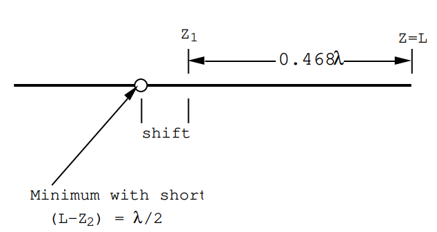
So upon shorting the line, the minimum moves 0.0327 λ towards the generator.
(b) \mathrm{VSWR}=\frac{1+|\Gamma|}{1-|\Gamma|}=\frac{1+.678}{1-.678}=\bf{5.21}
Problem (11.12).
A slotted line is terminated by a load impedance ZL = (10 - 10i) Ohms. The characteristic impedance of the slotted line is 50 Ohms. The voltage minimum is found to be at z1 on the line. When the load is replaced by a short the voltage minimum moves to z2.
(a) Calculate the shift \frac{\left(z_{1}-z_{2}\right)}{\lambda}. When the line is shorted does the minimum move towards the generator or towards the load?
(b) Calculate the Voltage Standing Wave Ratio, VSWR.
Answer (11.12).
(a) \mathrm{Z}_{\mathrm{L}}=10(1-\mathrm{i}) \text { Ohms }
\frac{Z_{L}}{Z_{0}}=\frac{1}{5}-\frac{i}{5}=z_{L}
\Gamma=\frac{z_{L}-1}{z_{L}+1}=\frac{-4 / 5-i / 5}{6 / 5-i / 5}=\frac{-4-i}{6-i}=\frac{-23-10 i}{37}.\nonumber
\therefore \Gamma=-0.622-0.27 \mathrm{i}=0.678 \mathrm{e}^{\mathrm{i} 1.13 \pi}\nonumber.
\theta=203.5^{\circ}=1.131 \pi \text { radians. }
Minimum when cos[2k(L-z) - θ] = -1
or \frac{4 \pi}{\lambda}(L-z)-1.13 \pi=\pi
∴ L-z=0.533 \lambda
When the load is replaced by a short, the minimum moves .0327 λ towards the load.
(b) \mathrm{VSWR}=\frac{1+|\Gamma|}{1-|\Gamma|}=\frac{1.678}{1-.678}=\bf{5.21}.
The same VSWR as for the impedance of problem (9.11).
Problem (11.13).
The Voltage Standing Wave Ratio is found to be S = 2.0 on a lossless 300 Ohm transmission line terminated by an unknown load impedance, ZL. The nearest voltage minimum is \frac{3 \lambda}{10} from the load i.e. z1 = (L - 0.3λ).
(a) When the above line is shorted where will the voltage minimum be located which is nearest the load, but not right at the load?
(b) Calculate the real and imaginary parts of the unknown load impedance, ZL.
Answer (11.13).
(a) When the load is replaced by a short the minimum will be located \frac{\lambda}{2} from the short.
\therefore \mathrm{z}_{2}=\mathrm{L}-\frac{\lambda}{2}
(b) S=V S W R=2.0=\frac{1+|\Gamma|}{1-|\Gamma|}
\therefore|\Gamma|=1 / 3 \Gamma=|\Gamma| e^{i \theta}
Minimum at z1 where
cos [2k(L-z) - θ] = -1
\mathrm{k}=\frac{2 \pi}{\lambda} and \frac{4 \pi}{\lambda}\left(L-z_{1}\right)-\theta=\pi
So \pi+\theta=\left(\frac{4 \pi}{\lambda}\right)\left(\frac{3 \lambda}{10}\right)=1.2 \pi
∴ θ = 0.2 \pi
So \Gamma=\frac{1}{3} e^{0.2 \pi i}
\Gamma=0.270+.196 \mathrm{i}
But z_{L}=\frac{Z_{L}}{Z_{0}}=\frac{1+\Gamma}{1-\Gamma}
∴ zL = 1.555 + .685 i
∴ ZL = (zL)(300) = 466.5 + 205.6i Ohms
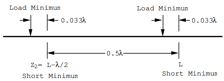
Problem (11.14). A slotted line is characterized by a velocity V= 3.00 x 10⁸ m/sec, and by a characteristic impedance of 50 Ohms. The slotted line is connected to an oscillator on one end and to an unknown load on the other end. The voltage standing wave ratio is found to be VWSR= 2.0. Moreover, when the load is replaced by a short circuit the position of the voltage minimum shifts 5 cm towards the load. The position of the first minimum from the shorted end occurs 40.0 cm from the short. Calculate the impedance of the load.
Answer (11.14).
The voltage minimum on a shorted line occurs at a distance λ/2 from the short; therefore for this problem the generator frequency corresponds to a wavelength of λ= 80 cm= 0.80 meters. The velocity on the slotted line is c= 3 x 10⁸ m/sec, so that the frequency is f= c/λ= 375 MHz. The corresponding circular frequency is ω= 2\pif = 2.356 x 10⁹ radians/sec. The wavevector on the line is k= 2\pi/λ = 7.854 m-1. Let the load be at z=L, with the generator somewhere to the left (at z=0). For a time dependence eiωt
V=a e^{-i k z}+b e^{i k z}\nonumber
and
\mathrm{z}_{0} \mathrm{I}=\mathrm{ae}^{-\mathrm{ikz}}-\mathrm{be}^{\mathrm{ikz}}.\nonumber
At z=L V=a e^{-i k L}+b e^{i k L}
and
\mathrm{z}_{0} \mathrm{I}=\mathrm{ae}^{-\mathrm{ikL}}-\mathrm{be}^{\mathrm{ikL}}\nonumber
Thus
\frac{z_{L}}{z_{0}}=\frac{1+(b / a) e^{2 i k L}}{1-(b / a) e^{2 i k L}}=\frac{1+\Gamma e^{i \theta}}{1-\Gamma e^{i \theta}},\nonumber
where
\left(\frac{\mathrm{b}}{\mathrm{a}}\right) \mathrm{e}^{2 \mathrm{ikL}}=\Gamma \mathrm{e}^{\mathrm{i} \theta}=\frac{\left(\mathrm{Z}_{\mathrm{L}} / \mathrm{Z}_{0}\right)-1}{\left(\mathrm{Z}_{\mathrm{L}} / \mathrm{Z}_{0}\right)+1}.\nonumber
One can write
V(z)=a e^{-i k z} \left(1+\Gamma e^{i \theta} e^{2 i k(z-L)}\right);\nonumber
clearly \left|\mathrm{V}_{\max }\right|=|\mathrm{a}|(1+\Gamma),
whereas \left|\mathrm{V}_{\min }\right|=|\mathrm{a}|(1-\Gamma),
so that \frac{\left|V_{\max }\right|}{|V_{min} |}=\frac{1+\Gamma}{1-\Gamma}=2.0
Therefore \Gamma=1 / 3. With the load connected the minimum occurs at z1. At the minimum e^{i\left(2 k\left(z_{1}-L\right)+\theta\right)}=-1,
or 2 \mathrm{k}\left(\mathrm{z}_{1}-\mathrm{L}\right)+\theta=\pm \pi\.
When the line is shorted the minimum occurs 40 cm from the load. With the load in place the minimum shifts 5 cm towards the generator. That means that z1 is such that L-z1= 45 cm = 0.5625λ. Thus
\theta=\pm \pi+2 k\left(L-z_{1}\right),\nonumber
or θ = ±\pi + 7.0686. The appropriate value is less than 2\pi so that θ = 3.9270 radians
\frac{Z_{L}}{Z_{0}}=\frac{1+\frac{1}{3} e^{3.927 i}}{1-\frac{1}{3} e^{3.927 i}}=0.562-i 0.298\nonumber
and the load impedance is ZL = 28.08 - i14.89 Ohms. This is equivalent to a resistance of 28.08 Ohms in series with a 28.5x10⁻¹² Farad capacitor.