
13.1: Alternating current in an inductance


- Last updated
- Mar 5, 2022
- Save as PDF

( \newcommand{\kernel}{\mathrm{null}\,}\)
In the Figure we see a current increasing to the right and passing through an inductor. As a consequence of the inductance, a back EMF will be induced, with the signs as indicated. I denote the back EMF by V=VA−VB. The back EMF is given by V=L˙I.
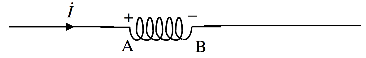
FIGURE XIII.1
Now suppose that the current is an alternating current given by
I=ˆIsinωt.
In that case ˙I=ˆIωcosωt, and therefore the back EMF is
V=ˆILωcosωt,
which can be written
V=ˆVcosωt,
where the peak voltage is
ˆV=LωˆI
and, of course VRMS=LωIRMS (Section 13.11).
The quantity Lω is called the inductive reactance XL. It is expressed in ohms (check the dimensions), and, the higher the frequency, the greater the reactance. (The frequency ν is ω/(2π).)
Comparison of equations ??? and ??? shows that the current and voltage are out of phase, and that V leads on I by 90o, as shown in Figure XIII.2.
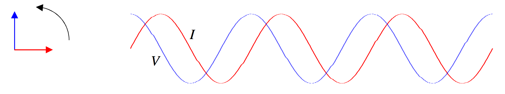
FIGURE XIII.2