
6.2: Electrostatic actuators and motors
- Page ID
- 25012
\( \newcommand{\vecs}[1]{\overset { \scriptstyle \rightharpoonup} {\mathbf{#1}} } \)
\( \newcommand{\vecd}[1]{\overset{-\!-\!\rightharpoonup}{\vphantom{a}\smash {#1}}} \)
\( \newcommand{\dsum}{\displaystyle\sum\limits} \)
\( \newcommand{\dint}{\displaystyle\int\limits} \)
\( \newcommand{\dlim}{\displaystyle\lim\limits} \)
\( \newcommand{\id}{\mathrm{id}}\) \( \newcommand{\Span}{\mathrm{span}}\)
( \newcommand{\kernel}{\mathrm{null}\,}\) \( \newcommand{\range}{\mathrm{range}\,}\)
\( \newcommand{\RealPart}{\mathrm{Re}}\) \( \newcommand{\ImaginaryPart}{\mathrm{Im}}\)
\( \newcommand{\Argument}{\mathrm{Arg}}\) \( \newcommand{\norm}[1]{\| #1 \|}\)
\( \newcommand{\inner}[2]{\langle #1, #2 \rangle}\)
\( \newcommand{\Span}{\mathrm{span}}\)
\( \newcommand{\id}{\mathrm{id}}\)
\( \newcommand{\Span}{\mathrm{span}}\)
\( \newcommand{\kernel}{\mathrm{null}\,}\)
\( \newcommand{\range}{\mathrm{range}\,}\)
\( \newcommand{\RealPart}{\mathrm{Re}}\)
\( \newcommand{\ImaginaryPart}{\mathrm{Im}}\)
\( \newcommand{\Argument}{\mathrm{Arg}}\)
\( \newcommand{\norm}[1]{\| #1 \|}\)
\( \newcommand{\inner}[2]{\langle #1, #2 \rangle}\)
\( \newcommand{\Span}{\mathrm{span}}\) \( \newcommand{\AA}{\unicode[.8,0]{x212B}}\)
\( \newcommand{\vectorA}[1]{\vec{#1}} % arrow\)
\( \newcommand{\vectorAt}[1]{\vec{\text{#1}}} % arrow\)
\( \newcommand{\vectorB}[1]{\overset { \scriptstyle \rightharpoonup} {\mathbf{#1}} } \)
\( \newcommand{\vectorC}[1]{\textbf{#1}} \)
\( \newcommand{\vectorD}[1]{\overrightarrow{#1}} \)
\( \newcommand{\vectorDt}[1]{\overrightarrow{\text{#1}}} \)
\( \newcommand{\vectE}[1]{\overset{-\!-\!\rightharpoonup}{\vphantom{a}\smash{\mathbf {#1}}}} \)
\( \newcommand{\vecs}[1]{\overset { \scriptstyle \rightharpoonup} {\mathbf{#1}} } \)
\(\newcommand{\longvect}{\overrightarrow}\)
\( \newcommand{\vecd}[1]{\overset{-\!-\!\rightharpoonup}{\vphantom{a}\smash {#1}}} \)
\(\newcommand{\avec}{\mathbf a}\) \(\newcommand{\bvec}{\mathbf b}\) \(\newcommand{\cvec}{\mathbf c}\) \(\newcommand{\dvec}{\mathbf d}\) \(\newcommand{\dtil}{\widetilde{\mathbf d}}\) \(\newcommand{\evec}{\mathbf e}\) \(\newcommand{\fvec}{\mathbf f}\) \(\newcommand{\nvec}{\mathbf n}\) \(\newcommand{\pvec}{\mathbf p}\) \(\newcommand{\qvec}{\mathbf q}\) \(\newcommand{\svec}{\mathbf s}\) \(\newcommand{\tvec}{\mathbf t}\) \(\newcommand{\uvec}{\mathbf u}\) \(\newcommand{\vvec}{\mathbf v}\) \(\newcommand{\wvec}{\mathbf w}\) \(\newcommand{\xvec}{\mathbf x}\) \(\newcommand{\yvec}{\mathbf y}\) \(\newcommand{\zvec}{\mathbf z}\) \(\newcommand{\rvec}{\mathbf r}\) \(\newcommand{\mvec}{\mathbf m}\) \(\newcommand{\zerovec}{\mathbf 0}\) \(\newcommand{\onevec}{\mathbf 1}\) \(\newcommand{\real}{\mathbb R}\) \(\newcommand{\twovec}[2]{\left[\begin{array}{r}#1 \\ #2 \end{array}\right]}\) \(\newcommand{\ctwovec}[2]{\left[\begin{array}{c}#1 \\ #2 \end{array}\right]}\) \(\newcommand{\threevec}[3]{\left[\begin{array}{r}#1 \\ #2 \\ #3 \end{array}\right]}\) \(\newcommand{\cthreevec}[3]{\left[\begin{array}{c}#1 \\ #2 \\ #3 \end{array}\right]}\) \(\newcommand{\fourvec}[4]{\left[\begin{array}{r}#1 \\ #2 \\ #3 \\ #4 \end{array}\right]}\) \(\newcommand{\cfourvec}[4]{\left[\begin{array}{c}#1 \\ #2 \\ #3 \\ #4 \end{array}\right]}\) \(\newcommand{\fivevec}[5]{\left[\begin{array}{r}#1 \\ #2 \\ #3 \\ #4 \\ #5 \\ \end{array}\right]}\) \(\newcommand{\cfivevec}[5]{\left[\begin{array}{c}#1 \\ #2 \\ #3 \\ #4 \\ #5 \\ \end{array}\right]}\) \(\newcommand{\mattwo}[4]{\left[\begin{array}{rr}#1 \amp #2 \\ #3 \amp #4 \\ \end{array}\right]}\) \(\newcommand{\laspan}[1]{\text{Span}\{#1\}}\) \(\newcommand{\bcal}{\cal B}\) \(\newcommand{\ccal}{\cal C}\) \(\newcommand{\scal}{\cal S}\) \(\newcommand{\wcal}{\cal W}\) \(\newcommand{\ecal}{\cal E}\) \(\newcommand{\coords}[2]{\left\{#1\right\}_{#2}}\) \(\newcommand{\gray}[1]{\color{gray}{#1}}\) \(\newcommand{\lgray}[1]{\color{lightgray}{#1}}\) \(\newcommand{\rank}{\operatorname{rank}}\) \(\newcommand{\row}{\text{Row}}\) \(\newcommand{\col}{\text{Col}}\) \(\renewcommand{\row}{\text{Row}}\) \(\newcommand{\nul}{\text{Nul}}\) \(\newcommand{\var}{\text{Var}}\) \(\newcommand{\corr}{\text{corr}}\) \(\newcommand{\len}[1]{\left|#1\right|}\) \(\newcommand{\bbar}{\overline{\bvec}}\) \(\newcommand{\bhat}{\widehat{\bvec}}\) \(\newcommand{\bperp}{\bvec^\perp}\) \(\newcommand{\xhat}{\widehat{\xvec}}\) \(\newcommand{\vhat}{\widehat{\vvec}}\) \(\newcommand{\uhat}{\widehat{\uvec}}\) \(\newcommand{\what}{\widehat{\wvec}}\) \(\newcommand{\Sighat}{\widehat{\Sigma}}\) \(\newcommand{\lt}{<}\) \(\newcommand{\gt}{>}\) \(\newcommand{\amp}{&}\) \(\definecolor{fillinmathshade}{gray}{0.9}\)Introduction to Micro-Electromechanical Systems (MEMS)
Chapter 6 elaborates on Chapter 5 by exploring a variety of motors, generators, and sensors in both linear and rotary configurations. Electric examples are analyzed in Section 6.2, and magnetic examples in Section 6.3. Section 6.2.1 reviews the background, while Sections 6.2.2 and 6.2.3 explore parallel-capacitor-plate devices using linear and rotary motion respectively. Section 6.2.4 discusses electrostatic motors exerting forces on dielectrics, while Section 6.2.5 discusses the limits to power density posed by electrical breakdown of air or other media, which limits peak electric field strength.
Micro-electromechanical systems (MEMS) are commonly used as motors, generators, actuators, and sensors and underlie one of the major current revolutions in electrical engineering, namely the extension of integrated circuit fabrication technology to electromechanical systems on the same substrate as the circuits with which they interoperate. Such devices now function as optical switches, radio-frequency switches, microphones, accelerometers, thermometers, pressure sensors, chemical sensors, micro-fluidic systems, electrostatic and magnetic motors, biological sensors, and other devices. They are used in systems as diverse as video projectors, automobile air bag triggers, and mechanical digital memories for hot environments.
Advantages of MEMS over their larger counterparts include size, weight, power consumption, and cost, and also much increased speed due to the extremely small masses and distances involved. For example, some MEMS electromechanical switches can operate at MHz frequencies, compared to typical speeds below ~1 kHz for most traditional mechanical devices. The feature size of MEMS ranges from sub-microns or microns up to one or more millimeters, although the basic electromagnetic principles apply to devices of any scale. Recent advances in micro-fabrication techniques, such as new lithography and etching techniques, precision micromolds, and improved laser cutting and chipping tools, have simplified MEMS development and extended their capabilities.
The Lorentz force law (6.2.1) is fundamental to all electric and magnetic motors and generators and expresses the force vector \(\overrightarrow{\mathrm{f}}\) [Newtons] acting on a charge q [Coulombs] as a function of the local electric field \(\overrightarrow{\mathrm{E}} \), magnetic field \(\overrightarrow{\mathrm{H}}\), and charge velocity vector \(\overrightarrow{\mathrm{v}}\) [ms -1]:
\[\overrightarrow{\mathrm{f}}=\mathrm{q}\left(\overrightarrow{\mathrm{E}}+\overrightarrow{\mathrm{v}} \times \mu_{\mathrm{o}} \overrightarrow{\mathrm{H}}\right)[\text { Newtons }] \nonumber \]
For the examples in Section 6.2 the velocities \(\overrightarrow{\mathrm{v}} \) and magnetic fields \( \overrightarrow{\mathrm{H}}\) are negligible, so the force is primarily electrostatic, \( \overrightarrow{\mathrm{f}}=\mathrm{q} \overrightarrow{\mathrm{E}}\), and can be readily found if \(\overrightarrow{\mathrm{E}} \) is known. When \( \overrightarrow{\mathrm{E}}\) is unknown, the energy method of Section 5.4.2 can often be used instead, as illustrated later. The power densities achievable in MEMS devices can be quite high, and are typically limited by materials failures, such as electrical breakdown or ohmic overheating.
Electrostatic actuators
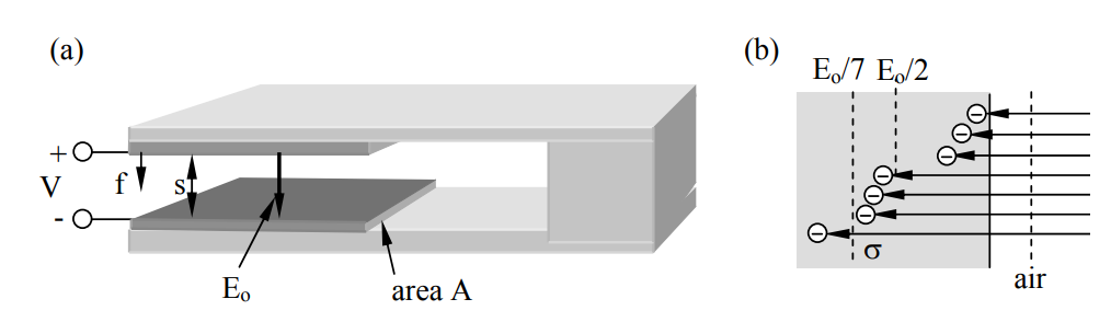
The simplest MEMS actuators use the electric force between two capacitor plates to pull them together, as illustrated in Figure 6.2.1(a) for a cantilevered loudspeaker or switch. The Lorentz force density F [N m-2] attracting the two plates is given by the \(\mathrm{q} \overrightarrow{\mathrm{E}}\) term in (6.2.1). Although one might suppose the force density on the upper plate is simply ρsE, where ρs is the surface charge density [C m-2] on that plate, the correct force is half this value because those charges nearer the surface screen those behind, as suggested in Figure 6.2.1(b); the charges furthest from the surface perceive almost no \(\overrightarrow{\mathrm{E}} \) at all. The figure shows a one-to-one correspondence between electric field lines and charges in a highly idealized distribution—reality is more random. The figure shows that the average field strength E perceived by the charges is half the surface field Eo, independent of their depth distribution ρ(z). Therefore the total attractive electric pressure is:
\[P_{e}=\rho_{s}\left(E_{o} / 2\right) \ \left[N m^{-2}\right] \nonumber \]
But the boundary condition at a conductor (2.6.15) is \(\hat{n} \bullet \overrightarrow{\mathrm{D}}=\rho_{\mathrm{s}}\), so:
\[\rho_{\mathrm{s}}=\varepsilon_{\mathrm{o}} \mathrm{E}_{\mathrm{o}} \nonumber \]
\[P_{e}=\varepsilon_{0} E_{o}^{2} / 2 \ \left[\mathrm{Nm}^{-2}\right] \quad \quad ( {electric \ pressure \ } \text{attracting capacitor plate}) \nonumber \]
This is the same pressure derived more rigorously in (5.2.4) and (5.4.3).
If Eo is near its breakdown value \(\mathrm{E}_{\mathrm{B}} \cong 10^{8}\left[\mathrm{V} \mathrm{m}^{-1}\right]\) for gaps less than ~10-6 meters, then the pressure \(\mathrm{P}=\varepsilon_{0} \mathrm{E}_{\mathrm{o}}^{2} / 2 \cong 8.8 \times 10^{-12} \times 10^{16} / 2=4.4 \times 10^{4} \ \left[\mathrm{N} \mathrm{m}^{-2}\right]\). A Newton is approximately the gravitational force on the apple that fell on Newton’s head (prompting his theory of gravity), or on a quarter-pound of butter. Therefore this maximum electrostatic force density is about one pound per square centimeter, comparable to that of a strong magnet.
The cantilever acts like a spring with a spring constant k, so the total force f is simply related to the deflection x: f = kx = PA, where A is the area of the capacitor plate. Thus the deflection is:
\[\mathrm{x}=\mathrm{PA} / \mathrm{k}=\varepsilon_{0} \mathrm{E}_{\mathrm{o}}^{2} \mathrm{A} / 2 \mathrm{k} \ [\mathrm{m}] \nonumber \]
The ratio A/k is controlled by the composition, thickness, and length of the cantilever, and the desired deflection is controlled by the application. For example, k must be adequate to overcome stiction19 in switches that make and break contact, and x must be adequate to ensure that the voltage between the capacitor plates does not cause arcing when the switch is open.
Alternatively both capacitor plates could be charged positive or negative so they repel each other. In this case the charge Q moves to the outside surfaces and connects to the very same field strengths as before due to boundary conditions (E = Q/εoA), except that the negative pressure εoE2/2 on the two plates acts to pull them apart rather than together. The field between the plates is then zero.
19 Stiction is the force that must be overcome when separating two contacting surfaces. These forces often become important for micron-sized objects, particularly for good conductors in contact for long periods.
Even with extreme electric field strengths the power density [W m-3] available with linear motion MEMS actuators may be insufficient. Power equals force times velocity, and rotary velocities can be much greater than linear velocities in systems with limited stroke, such as the cantilever of Figure 6.2.1(a) or the lateral-displacement systems illustrated in Figure 6.2.2. Since it is difficult to compute the lateral electric fields responsible for the lateral forces in rotary or linear systems [e.g., the z components in Figure 6.2.2(a)], the energy methods described below are generally used instead.
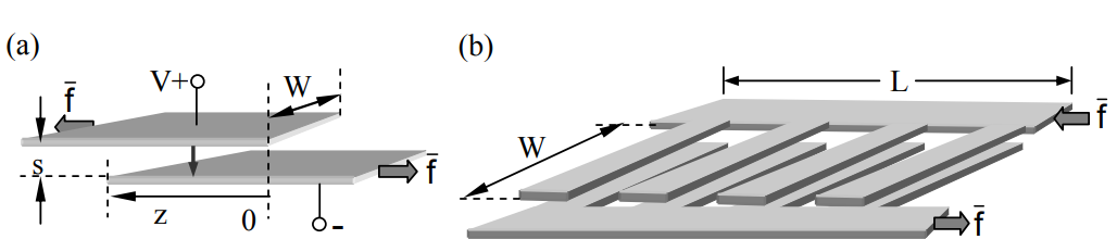
The two charged parallel plates illustrated in Figure 6.2.2(a) are pulled laterally toward one another (z increases) because opposite charges attract. The force \(\overrightarrow{\mathrm{f}} \) required to pull the plates apart depends only on their electric charge q and the plate geometry, independent of any attached circuit. This force \(\overrightarrow{\mathrm{f}}\) in the -z direction can be found by noting that f does work on the capacitor/circuit system, increasing its total energy wT if f is positive:
\[\mathrm{f}=-\mathrm{d} \mathrm{w}_{\mathrm{T}} / \mathrm{d} \mathrm{z}=-\mathrm{d} \mathrm{w}_{\mathrm{e}} / \mathrm{d} \mathrm{z}-\mathrm{V} \mathrm{d} \mathrm{q} / \mathrm{d} \mathrm{z} \ [\mathrm{N}] \qquad \qquad \qquad \text { (energy-force equation) } \nonumber \]
where we is the electric energy stored in the capacitor, V is the capacitor voltage20, and dq is incremental charge flowing from any attached circuit into the positive terminal of the capacitor. The negative sign in (6.2.6) results because f is in the -z direction. Since this energy-force equation is correct regardless of any attached circuit, we can evaluate it for an attached open circuit, battery, or arbitrary Thevenin equivalent, provided it results in the given capacitor voltage V and charge q.
The force computed using (6.2.6) is the same for any attached circuit and any form of the energy expression (3.1.16):
\[\mathrm{w}_{\mathrm{e}}=\mathrm{CV}^{2} / 2=\mathrm{q}^{2} / 2 \mathrm{C} \ [\mathrm{J}] \qquad\qquad\qquad \text { (electric energy in a capacitor) } \nonumber \]
The algebra is minimized, however, if we assume the capacitor is open-circuit so that q is constant and dq/dz = 0 in (6.2.6). Because V depends on z in this case, it is simpler to use we = q2/2C to evaluate (6.2.6), where: 1) C = εoWz/s [F], 2) the overlap area of the capacitor is Wz, 3) the plate separation is s << W, and 4) we neglect fringing fields. Thus (6.2.6) becomes:
\[\mathrm{f}=-\left(\mathrm{q}^{2} / 2\right)\left(\mathrm{dC}^{-1} / \mathrm{dz}\right)=-\left(\mathrm{q}^{2} / 2\right)\left(\mathrm{s} / \varepsilon_{0} \mathrm{W}\right) \mathrm{d} \mathrm{z}^{-1} / \mathrm{dz}=\left(\mathrm{q}^{2} / 2\right)\left(\mathrm{s} / \varepsilon_{0} \mathrm{Wz}^{2}\right) \ [\mathrm{N}] \nonumber \]
20 For convenience, V represents voltage and v represents velocity in this section.
The rapid increase in force as z → 0 results because q is constant and concentrates at the ends of the plates as the overlap approaches zero; z→0 also violates the assumption that fringing fields can be neglected.
It is interesting to relate the force f of (6.2.8) to the electric field strength E, where:
\[\mathrm{E}=\rho_{\mathrm{s}} / \varepsilon_{\mathrm{o}}=\mathrm{q} / \mathrm{Wz} \varepsilon_{\mathrm{o}} \ \left[\mathrm{V} \mathrm{m}^{-1}\right] \nonumber \]
\[\mathrm{q}=\mathrm{Wz} \varepsilon_{0} \mathrm{E}=\mathrm{Wz} \varepsilon_{\mathrm{o}} \mathrm{V} / \mathrm{s} \ [\mathrm{C}] \nonumber \]
\[\mathrm{f}=\mathrm{q}^{2} \mathrm{s} / 2 \varepsilon_{\mathrm{o}} \mathrm{Wz}^{2}=\mathrm{Ws} \varepsilon_{\mathrm{o}} \mathrm{E}^{2} / 2=\mathrm{A}^{\prime} \mathrm{P}_{\mathrm{e}} \ [\mathrm{N}] \qquad\qquad\qquad \text { (lateral electric force) } \nonumber \]
where A' = Ws is the cross-sectional area of the gap perpendicular to \( \overrightarrow{\mathrm{f}}\), and \(\mathrm{P}_{\mathrm{e}}=\Delta \mathrm{W}_{\mathrm{e}}=\varepsilon_{\mathrm{o}} \mathrm{E}^{2} / 2 - 0\) is the electric pressure difference acting at the end of the capacitor. Note that this pressure is perpendicular to \(\overrightarrow{\mathrm{E}}\) and is “pushing” into the adjacent field-free region where We = 0; in contrast, the pressure parallel to \(\overrightarrow{\mathrm{E}}\) always “pulls”. Later we shall find that “magnetic pressure” Pm = ΔWm is similarly attractive parallel to \(\overrightarrow{\mathrm{H}}\) and pushes in directions orthogonal to \(\overrightarrow{\mathrm{H}}\).
Note that if V is constant, then the force f (6.2.11) does not depend on z and is maximized as s→0. For a fixed V, the minimum practical plate separation s corresponds to E near the threshold of electrical breakdown, which is discussed further in Section 6.2.5. Also note that the force f is proportional to W, which can be maximized using multiple fingers similar to those illustrated in Figure 6.2.2(b). Actuator and motor designs generally maximize f and W while preserving the desired stroke21.
21 The “stroke” of an actuator is its range of positions; in Figure 6.2.2(a) it would be the maximum minus the minimum value of z. Although the force (6.2.11) becomes infinite as the minimum z → 0 for constant q, this would violate the assumption z >> d and can cause V→∞; V is usually held constant, however.
Design a small electrostatic overlapping plate linear actuator that opens a latch by moving 1 mm with a force of 10-2 Newtons.
Solution
The two-plate actuator illustrated in Figure 6.2.2(a) exerts a force f = WsεoE2 (6.2.11). If E is near the maximum dry-gas value of ~3.2×10⁶ V m-1, the gap s = 1 mm, and W = 1 cm, then f = 10-2 × 10-3 × 8.85 × 10-12 × 1013 = 8.85×10⁻⁴ [N]. By using M fingers, each wider than the 1-mm stroke, the force can be increased by M [see Figure 6.2.2(b)]. If we let M = 12 the device yields f = 1.06×10⁻², but its length L must be greater than 12 times twice the finger width (see figure), where the finger width G must exceed not only the stroke but also several times s, in order to make fringing fields negligible. If G ≅ 4 mm, then the actuator length is 12×2×4 mm = 9.6 cm, large compared to the width. A three-plate actuator with two grounded plates on the outside and one charged plate inside would double the force, halve the length L, protect users from electrocution, and simplify sealing the actuator against moisture that could short-circuit the plates. The plate voltage V = Es = 3200 volts. This design is not unique, of course.
Rotary electrostatic motors
Because forces (6.2.4) or (6.2.11) in electrostatic motors are limited by the maximum electric field strength E possible without electric arcing, higher power densities [W m-3] require higher speeds since the power P = fv [watts], where f is force [N], and v is velocity [m s-1]. Figure 6.2.3 pictures an ideal 4-segment rotary electrostatic motor for which v and the resulting centrifugal forces are ultimately limited by the tensile strength of the rotor. For both materials and aerodynamic reasons the maximum v at the rotor tip is usually somewhat less than the speed of sound, ~340 m/s. Some rotors spin much faster in vacuum if the material can withstand the centrifugal force.
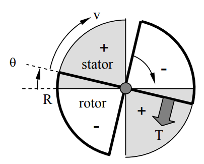
This motor has radius R, plate separation s, and operating voltage V. Stationary “stator” plates occupy two quadrants of the motor and a second pair of quadrant plates (the “rotor”) can rotate to yield an overlap area A = R2θ [m2] that varies from zero to \(\pi\)R2/2 as θ increases from zero to \(\pi\)/2. If the voltage V is applied across the plates, a torque T is produced22, where:
\[\mathrm{T}=-\mathrm{d} \mathrm{w}_{\mathrm{T}} / \mathrm{d} \theta \ [\mathrm{N} \mathrm{m}] \nonumber \]
and dwT is the increment by which the total system energy (fields plus battery) is increased as a result of the motion dθ. The negative sign in (6.2.12) reflects the fact that the torque T is applied by the motor to the environment. If we replace the overlap area of Wz in (6.2.8) by its equivalent R2θ, then (6.2.8) and (6.2.12) become:
\[\mathrm{w}_{\mathrm{e}}=\mathrm{Q}^{2} / 2 \mathrm{C}=\mathrm{Q}^{2} \mathrm{s} / 2 \varepsilon_{\mathrm{o}} \mathrm{R}^{2} \theta \nonumber \]
\[\mathrm{T}=-\mathrm{d} \mathrm{w}_{\mathrm{T}} / \mathrm{d} \theta=\mathrm{Q}^{2} \mathrm{s} / 2 \varepsilon_{\mathrm{o}} \mathrm{R}^{2} \theta^{2}=\varepsilon_{\mathrm{o}} \mathrm{R}^{2} \mathrm{V}^{2} / \mathrm{s} \ [\mathrm{N} \mathrm{m}] \nonumber \]
where Q = εoR2θV/s [C], which follows from (6.2.10) where Wz → R2θ [m2].
22 Torque T [Nm] equals the force f on a lever times its length L. Therefore the mechanical work performed by the torque is wm = fx = fL(x/L) = Tθ, where θ = x/L is the angle (radians) through which the lever rotates about its pivot at one end. Power is Tdθ/dt = Tω [W].
If we assume R = 10-3, s = 10-6, and V = 3 volts (corresponding to 3×10⁶ Vm-1, below the breakdown limit discussed in Section 6.2.5; then (6.2.14) yields:
\[\mathrm{T}=8.8 \times 10^{-12} \times\left(10^{-3}\right)^{2} 3^{2} / 10^{-6} \cong 7.9 \times 10^{-11 } \ [\mathrm{N} \mathrm{m}] \nonumber \]
This torque exists only until the plates fully overlap, at which time the voltage V is switched to zero until the plates coast another 90° and V is restored. The duty cycle of this motor is thus 0.5 because T ≠ 0 only half of the time.
A single such ideal motor can then deliver an average of Tω/2 watts, where the factor ½ reflects the duty cycle, and Tω is the mechanical power associated with torque T on a shaft rotating at ω radians s-1. If the tip velocity v of this rotor is 300 ms-1, slightly less than the speed of sound so as to reduce drag losses while maximizing ω, then the corresponding angular velocity ω is v/R = 300/10-3 = 3×10⁵ radians s-1 or ~3×10⁶ rpm, and the available power Tω/2 ≅ 7.9×10-11 × 3×105/2 ≅ 1.2×10⁻⁵ watts if we neglect all losses. In principle one might pack ~25,000 motors into one cubic centimeter if each motor were 10 microns thick, yielding ~0.3 W/cm3 . By using a motor with N segments instead of 4 this power density and torque could be increased by a factor of N/4. The small micron-sized gap s would permit values of N as high as ~500 before the fringing fields become important, and power densities of ~40 W/cm-3.
This 40-W/cm3 power density can be compared to that of a 200-hp automobile engine that delivers 200×746 watts23 and occupies 0.1 m3 , yielding only ~1.5 W/cm3 . Extremely high power densities are practical only in tiny MEMS devices because heat and torque are then easier to remove, and because only micron-scale gaps permit the highest field strengths, as explained in Section 6.2.5. Rotary MEMS motors have great potential for extremely low power applications where torque extraction can be efficient; examples include drivers for micro-gas-turbines and pumps. The field of MEMS motors is still young, so their full potential remains unknown.
23 There are 746 watts per horsepower.
Dielectric actuators and motors
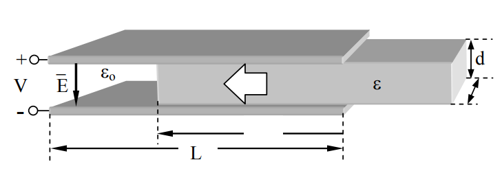
One difficulty with the rotary motor of Figure 6.2.3 is that voltage must be applied to the moving vanes across a sliding mechanical boundary. One alternative is to use a dielectric rotor driven by voltages applied only to the stator. The configuration could be similar to that of Figure 6.2.3 but the rotor would be dielectric and mounted between identical conducting stators with a potential V between them that is turned on and off at times so as to produce an average torque as the rotor rotates. Figure 6.2.4 illustrates the concept in terms of a linear actuator for which the force f can more easily be found. We again assume that fringing fields can be neglected because W >> d.
The force f can be found by differentiating the total stored electric energy we with respect to motion z, where C is the effective capacitance of this structure, and:
\[\mathrm{w}_{\mathrm{e}}=\mathrm{CV}^{2} / 2=\mathrm{Q}^{2} / 2 \mathrm{C} \ [\mathrm{J}] \nonumber \]
To simplify differentiating we with respect to z, it is easier to use the expression we = Q2/2C because is this case Q is independent of z whereas C is not.
For two capacitors in parallel C = Co + Cε (3.1.14), where Co and Cε are the capacitances associated with the air and dielectric halves of the actuator, respectively. Capacitance C was defined in (3.1.8), and equals εA/s where A is the plate area and s is the plate separation. It follows that:
\[\mathrm{C}=\mathrm{C}_{\varepsilon}+\mathrm{C}_{\mathrm{o}}=\varepsilon \mathrm{zW} / \mathrm{s}+\varepsilon_{\mathrm{o}}(\mathrm{L}-\mathrm{z}) \mathrm{W} / \mathrm{s}=\left[\mathrm{z}\left(\varepsilon-\varepsilon_{\mathrm{o}}\right)+\varepsilon_{\mathrm{o}} \mathrm{L}\right] \mathrm{W} / \mathrm{s} \nonumber \]
The force f pulling the dielectric slab between the charged plates is given by the forceenergy relation (6.2.6) and can be combined with (6.2.16) and (6.2.17) to yield:
\[\begin{align} \mathrm{f} & \cong-\mathrm{d} \mathrm{w}_{\mathrm{e}} / \mathrm{d} \mathrm{z}=-\mathrm{d}\left(\mathrm{Q}^{2} / 2 \mathrm{C}\right) / \mathrm{d} \mathrm{z}=-\left(\mathrm{Q}^{2} \mathrm{s} / 2 \mathrm{W}\right) \mathrm{d}\left[\mathrm{z}\left(\varepsilon-\varepsilon_{\mathrm{o}}\right)+\varepsilon_{\mathrm{o}} \mathrm{L}\right]^{-1} / \mathrm{d} \mathrm{z} \\ &=\left(\mathrm{Q}^{2} \mathrm{s} / 2 \mathrm{W}\right)\left[\mathrm{z}\left(\varepsilon-\varepsilon_{\mathrm{o}}\right)+\varepsilon_{\mathrm{o}} \mathrm{L}\right]^{-2}\left(\varepsilon-\varepsilon_{\mathrm{o}}\right)=\left(\mathrm{Q}^{2} \mathrm{W} / 2 \mathrm{s} \mathrm{C}^{2}\right)\left(\varepsilon-\varepsilon_{\mathrm{o}}\right) \ [\mathrm{N}] \nonumber \end{align} \nonumber \]
This force can be expressed in terms of the electric field strength E between the two plates by substituting into (6.2.18) the expressions Q = CV and V = Es:
\[\mathrm{f} \cong\left(\mathrm{E}^{2} \mathrm{s} \mathrm{W} / 2\right)\left(\varepsilon-\varepsilon_{\mathrm{o}}\right)=\left[\left(\varepsilon-\varepsilon_{\mathrm{o}}\right) \mathrm{E}^{2} / 2\right] \mathrm{W} \mathrm{s}=\Delta \mathrm{P}_{\mathrm{e}} \mathrm{A} \ [\mathrm{N}] \nonumber \]
where A = Ws is the area of the endface of the dielectric slab, and the differential electric pressure pulling the slab between the charged plates is:
\[\Delta \mathrm{P}_{\mathrm{e}}=\left(\varepsilon-\varepsilon_{\mathrm{o}}\right) \mathrm{E}^{2} / 2 \ \left[\mathrm{Nm}^{-2}\right] \nonumber \]
The differential pressure ΔPe pushing the interface into the capacitor is thus the difference between the electric pressure on one side of the dielectric interface and that on the other, where the pressure Pe on each side is simply the electric energy density there:
\[\mathrm{P}_{\mathrm{e}}=\varepsilon \mathrm{E}^{2} / 2 \ \left[\mathrm{Nm}^{-2}\right],\left[\mathrm{Jm}^{-3}\right] \nonumber \]
Because the electric field at the right-hand end of the slab approaches zero, it exerts no additional force. Electric pressure is discussed further in Section 5.5.2.
Applying these ideas to the rotary motor of Figure 6.2.3 simply involves replacing the rotor by its dielectric equivalent and situating it between conducting stator plates that are excited by V volts so as to pull each dielectric quadrant into the space between them. Then V is switched to zero as the dielectric exits that space so the rotor can coast unpowered until the dielectric quadrants start entering the next pair of stator plates. Thus the drive voltage V is non-zero half the time, with two voltage pulses per revolution of this two-quadrant rotor. The timing of the voltages must be responsive to the exact position of the rotor, which is often determined by a separate rotor angular position sensor. Start-up can fail if the rotor is in exactly the wrong position where f = 0 regardless of V, and the rotor will spin backwards if it starts from the wrong position. Figure 6.3.6 suggests how multiple segments and excitation phases can avoid this problem in the context of magnetic motors.
Design a maximum-power-density rotary electrostatic motor that delivers 10 W power at ω ≅ 106 r s-1 without make/break or sliding electrical contacts.
Solution
A segmented dielectric rotor sandwiched between charged conducting plates avoids sliding electrical contacts. Assume the rotor has radius R, thickness s, and is made of two electrically insulated dielectrics having permittivities ε = 10εo and εo, and that they are radially segmented as is the rotor in Figure 6.2.3, but with M segments rather than 4. The maximum pressure on the edges of the rotor dielectric boundaries between ε and εo is ΔPe = (ε - εo)E2 /2 [N m-2]. The mechanical power delivered during the half cycle the voltages are applied to the plate is Tω = 20 = ΔPe(R/2)sMω. Let’s arbitrarily set s = 10-6, E = 106 [V m-1], and M = 800. Therefore R = 2×20/(sMωΔPe) = 40/[10-6×800×106×9×8.85×10-12×(106)2 /2] = 1.3×10⁻³ [m]. The operating voltage is Es ≅ 1 volt and the power density is ~105 W/cm3 .
Electrical breakdown
In every case the torque or force produced by an electrostatic MEMS actuator or motor is limited by the breakdown field EB = VB/d, where VB is the breakdown voltage, and the dependence of EB on d is non-linear. Electric breakdown of a gas occurs when stray free electrons accelerated by E acquire enough velocity and energy (a few electron volts24) to knock additional free electrons off gas molecules when they collide, thus triggering a chain reaction that leads to arcing and potentially destructive currents. Water molecules shed electrons much more easily in collisions than do nitrogen or oxygen molecules, and so EB is much lower in moist air. This is why it is easier to draw visible sparks in cold dry winter air than it is in summer, because in winter the field strengths can be much greater before breakdown occurs, and such high-voltage breakdowns are more visible.
24 An electron volt is the energy acquired by an electron or other equally charged particle as it accelerates through a potential difference of one volt. It is equivalent to e = 1.6021×10⁻¹⁹ Joules.
If, however, the gap between the two electrodes is sufficiently small, the probability diminishes that an ionizing collision will occur between any free electron and a gas atom before the electron hits the positively charged electrode. This mean-free-path, or average distance before a “collision”, for free electrons is on the order of one micron in air, so breakdown is inhibited for gaps less than the mean free path. However, even when the gap is so narrow that gas breakdown is unlikely, if the field strength E is increased to ~3 × 10⁸ [V m-1], or two orders of magnitude beyond typical values for EB in dry gas, any free electrons can then acquire enough energy to knock an ion loose from the positively charged wall. Such a positive ion can then acquire enough energy to release multiple electrons when it impacts the negatively charged wall, producing another form of chain reaction, electrical arcing, and breakdown.
The reasons electric actuators and motors are so attractive on the scale of MEMS, but almost never used at larger scales, are therefore that: 1) the breakdown field strength EB increases approximately two orders of magnitude for micron-sized gaps, enabling force densities up to four orders of magnitude greater than usual, and 2) enormous values for E and pressure can be achieved with reasonable voltages across micron or sub-micron gaps (⇒ ~3×10⁸ [V m-1] and ~10 lb/cm2 ).
The breakdown fields for materials are problematic because any local defect can concentrate field strengths locally, exceeding the threshold. Fields of ~106 Vm-1 are a nominal upper bound, although somewhat higher values are obtained in integrated circuits.