
13.6: Admittance
- Page ID
- 5499

\( \newcommand{\vecs}[1]{\overset { \scriptstyle \rightharpoonup} {\mathbf{#1}} } \)
\( \newcommand{\vecd}[1]{\overset{-\!-\!\rightharpoonup}{\vphantom{a}\smash {#1}}} \)
\( \newcommand{\dsum}{\displaystyle\sum\limits} \)
\( \newcommand{\dint}{\displaystyle\int\limits} \)
\( \newcommand{\dlim}{\displaystyle\lim\limits} \)
\( \newcommand{\id}{\mathrm{id}}\) \( \newcommand{\Span}{\mathrm{span}}\)
( \newcommand{\kernel}{\mathrm{null}\,}\) \( \newcommand{\range}{\mathrm{range}\,}\)
\( \newcommand{\RealPart}{\mathrm{Re}}\) \( \newcommand{\ImaginaryPart}{\mathrm{Im}}\)
\( \newcommand{\Argument}{\mathrm{Arg}}\) \( \newcommand{\norm}[1]{\| #1 \|}\)
\( \newcommand{\inner}[2]{\langle #1, #2 \rangle}\)
\( \newcommand{\Span}{\mathrm{span}}\)
\( \newcommand{\id}{\mathrm{id}}\)
\( \newcommand{\Span}{\mathrm{span}}\)
\( \newcommand{\kernel}{\mathrm{null}\,}\)
\( \newcommand{\range}{\mathrm{range}\,}\)
\( \newcommand{\RealPart}{\mathrm{Re}}\)
\( \newcommand{\ImaginaryPart}{\mathrm{Im}}\)
\( \newcommand{\Argument}{\mathrm{Arg}}\)
\( \newcommand{\norm}[1]{\| #1 \|}\)
\( \newcommand{\inner}[2]{\langle #1, #2 \rangle}\)
\( \newcommand{\Span}{\mathrm{span}}\) \( \newcommand{\AA}{\unicode[.8,0]{x212B}}\)
\( \newcommand{\vectorA}[1]{\vec{#1}} % arrow\)
\( \newcommand{\vectorAt}[1]{\vec{\text{#1}}} % arrow\)
\( \newcommand{\vectorB}[1]{\overset { \scriptstyle \rightharpoonup} {\mathbf{#1}} } \)
\( \newcommand{\vectorC}[1]{\textbf{#1}} \)
\( \newcommand{\vectorD}[1]{\overrightarrow{#1}} \)
\( \newcommand{\vectorDt}[1]{\overrightarrow{\text{#1}}} \)
\( \newcommand{\vectE}[1]{\overset{-\!-\!\rightharpoonup}{\vphantom{a}\smash{\mathbf {#1}}}} \)
\( \newcommand{\vecs}[1]{\overset { \scriptstyle \rightharpoonup} {\mathbf{#1}} } \)
\(\newcommand{\longvect}{\overrightarrow}\)
\( \newcommand{\vecd}[1]{\overset{-\!-\!\rightharpoonup}{\vphantom{a}\smash {#1}}} \)
\(\newcommand{\avec}{\mathbf a}\) \(\newcommand{\bvec}{\mathbf b}\) \(\newcommand{\cvec}{\mathbf c}\) \(\newcommand{\dvec}{\mathbf d}\) \(\newcommand{\dtil}{\widetilde{\mathbf d}}\) \(\newcommand{\evec}{\mathbf e}\) \(\newcommand{\fvec}{\mathbf f}\) \(\newcommand{\nvec}{\mathbf n}\) \(\newcommand{\pvec}{\mathbf p}\) \(\newcommand{\qvec}{\mathbf q}\) \(\newcommand{\svec}{\mathbf s}\) \(\newcommand{\tvec}{\mathbf t}\) \(\newcommand{\uvec}{\mathbf u}\) \(\newcommand{\vvec}{\mathbf v}\) \(\newcommand{\wvec}{\mathbf w}\) \(\newcommand{\xvec}{\mathbf x}\) \(\newcommand{\yvec}{\mathbf y}\) \(\newcommand{\zvec}{\mathbf z}\) \(\newcommand{\rvec}{\mathbf r}\) \(\newcommand{\mvec}{\mathbf m}\) \(\newcommand{\zerovec}{\mathbf 0}\) \(\newcommand{\onevec}{\mathbf 1}\) \(\newcommand{\real}{\mathbb R}\) \(\newcommand{\twovec}[2]{\left[\begin{array}{r}#1 \\ #2 \end{array}\right]}\) \(\newcommand{\ctwovec}[2]{\left[\begin{array}{c}#1 \\ #2 \end{array}\right]}\) \(\newcommand{\threevec}[3]{\left[\begin{array}{r}#1 \\ #2 \\ #3 \end{array}\right]}\) \(\newcommand{\cthreevec}[3]{\left[\begin{array}{c}#1 \\ #2 \\ #3 \end{array}\right]}\) \(\newcommand{\fourvec}[4]{\left[\begin{array}{r}#1 \\ #2 \\ #3 \\ #4 \end{array}\right]}\) \(\newcommand{\cfourvec}[4]{\left[\begin{array}{c}#1 \\ #2 \\ #3 \\ #4 \end{array}\right]}\) \(\newcommand{\fivevec}[5]{\left[\begin{array}{r}#1 \\ #2 \\ #3 \\ #4 \\ #5 \\ \end{array}\right]}\) \(\newcommand{\cfivevec}[5]{\left[\begin{array}{c}#1 \\ #2 \\ #3 \\ #4 \\ #5 \\ \end{array}\right]}\) \(\newcommand{\mattwo}[4]{\left[\begin{array}{rr}#1 \amp #2 \\ #3 \amp #4 \\ \end{array}\right]}\) \(\newcommand{\laspan}[1]{\text{Span}\{#1\}}\) \(\newcommand{\bcal}{\cal B}\) \(\newcommand{\ccal}{\cal C}\) \(\newcommand{\scal}{\cal S}\) \(\newcommand{\wcal}{\cal W}\) \(\newcommand{\ecal}{\cal E}\) \(\newcommand{\coords}[2]{\left\{#1\right\}_{#2}}\) \(\newcommand{\gray}[1]{\color{gray}{#1}}\) \(\newcommand{\lgray}[1]{\color{lightgray}{#1}}\) \(\newcommand{\rank}{\operatorname{rank}}\) \(\newcommand{\row}{\text{Row}}\) \(\newcommand{\col}{\text{Col}}\) \(\renewcommand{\row}{\text{Row}}\) \(\newcommand{\nul}{\text{Nul}}\) \(\newcommand{\var}{\text{Var}}\) \(\newcommand{\corr}{\text{corr}}\) \(\newcommand{\len}[1]{\left|#1\right|}\) \(\newcommand{\bbar}{\overline{\bvec}}\) \(\newcommand{\bhat}{\widehat{\bvec}}\) \(\newcommand{\bperp}{\bvec^\perp}\) \(\newcommand{\xhat}{\widehat{\xvec}}\) \(\newcommand{\vhat}{\widehat{\vvec}}\) \(\newcommand{\uhat}{\widehat{\uvec}}\) \(\newcommand{\what}{\widehat{\wvec}}\) \(\newcommand{\Sighat}{\widehat{\Sigma}}\) \(\newcommand{\lt}{<}\) \(\newcommand{\gt}{>}\) \(\newcommand{\amp}{&}\) \(\definecolor{fillinmathshade}{gray}{0.9}\)In general, the impedance of a circuit is partly resistive and partly reactive:
\[\label{13.6.2}Z=R+jX.\]
The real part is the resistance, and the imaginary part is the reactance. The relation between \(V\) and \(I\) is \(V = IZ\). If the circuit is purely resistive, \(V\) and \(I\) are in phase. If is it purely reactive, \(V\) and \(I\) differ in phase by 90o. The reactance may be partly inductive and partly capacitive, so that
\[\label{13.6.3}Z=R+j(X_L+X_C). \]
Indeed we shall describe such a system in detail in the next section. Note that \(X_C\) is negative.
The Equation \ref{13.6.3} is sometimes written \(Z=R+j(X_L-X_C)\), in which \(X_C\) is intended to represent the unsigned quantity \(1/(C\omega)\). In these notes \(X_C\) is intended to represent \(-1/(C\omega)\).
The reciprocal of the impedance \(Z\) is the admittance, \(Y\).
Thus
\[\label{13.6.4}Y=\dfrac{1}{Z}=\dfrac{1}{R+jX}.\]
And of course, since \(V = IZ,\, I = VY\).
Whenever we see a complex (or a purely imaginary) number in the denominator of an expression, we always immediately multiply top and bottom by the complex conjugate, so Equation \ref{13.6.4} becomes
\[\label{13.6.5}Y=\dfrac{Z^*}{|Z|^2}=\dfrac{R-jX}{R^2+X^2}.\]
This can be written
\[\label{13.6.6}Y=G+jB,\]
where the real part, \(G\), is the conductance:
\[\label{13.6.7}G=\dfrac{R}{R^2+X^2},\]
and the imaginary part, \(B\), is the susceptance:
\[\label{13.6.8}B=-\dfrac{X}{R^2+X^2}.\]
The SI unit for admittance, conductance and susceptance is the siemens (or the "mho" in informal talk).
I leave it to the reader to show that
\[\label{13.6.9}R=\dfrac{G}{G^2+B^2}\]
and
\[\label{13.6.10}X=-\dfrac{B}{G^2+B^2}.\]
What is the impedance of the circuit below to alternating current of frequency \(2000/\pi \text{ Hz}\) (\(\omega = 4000\text{ rad s}^{-1}\))?

Solution
I think that the following will be readily agreed. (Remember, the admittance is the reciprocal of the impedance; and, whenever you see a complex number in a denominator, immediately multiply top and bottom by the conjugate.)
Impedance of \(\text{AB} = 25(1 -2j) \Omega\)
Impedance of \(\text{CD} = 20(2 + j) \Omega\)
Admittance of \(\text{AB} = \dfrac{1+2j}{125} \text{ S} \)
Admittance of \(\text{CD} = \dfrac{2-j}{100} \text{ S} \)
Admittance of the circuit = \(\dfrac{28+6j}{1000}\text{ S}\)
Impedance of the circuit = \(\dfrac{100(14-3j)}{41}\Omega\)
The current leads on the voltage by 12º.
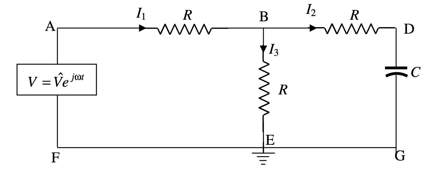
Three resistors and a capacitor are connected to an \(\text{AC}\) voltage source as shown. The point \(\text{E}\) is grounded (earthed), and its potential can be taken as zero. Calculate the three currents, and the potential at \(\text{B}\).
Solution
We can do this by using Kirchhoff’s rules in the usual way. When I did this I found the algebra to be slightly heavy going, and I found that it was much simplified by writing \(\dfrac{1}{C\omega}=aR\), where \(a\) is a dimensionless number. Then, instead of writing the impedance of the section BDG as \(R-\dfrac{j}{C\omega}\), I write it as \(R(1-ja)\).
Kirchhoff’s rules, applied to two circuits and the point \(\text{B}\), are
\[\label{13.6.11}V=I_1R+I_2R\]
\[\label{13.6.12}I_2(1-ja)-I_3=0\]
\[\label{13.6.13}I_1=I_2+I_3\]
These equations are to be solved for the three currents \(I_1,I_2,I_3\). These will all be complex numbers, representing alternating currents. Solution could proceed, for example, by eliminating \(I_3\) from equations \ref{13.6.11} and \ref{13.6.12}, and then eliminating \(I_3\) from equations \ref{13.6.11} and \ref{13.6.13}. This results in two equations in \(I_1\) and \(I_2\). We can eliminate \(I_1\) from these to obtain \(I_2\). I make it \(I_2=\dfrac{V}{R(3-2aj)}\), but then we immediately multiply top and bottom by \(3+2aj\) to obtain
\[\label{13.6.14}I_2=\left ( \dfrac{3+2aj}{9+4a^2}\right ) \dfrac{V}{R}\]
It is then straightforward to return to the original equations to obtain
\[\label{13.6.15}I_1 = \left ( \dfrac{6+2a^2+aj}{9+4a^2}\right ) \dfrac{V}{R}\]
and
\[\label{13.6.16}I_3 = \left ( \dfrac{3+2a^2 -aj}{9+4a^2}\right ) \dfrac{V}{R}\]
For example, suppose that the frequency and the capacitance were such that \(a = 1\), then
\[\label{13.6.17}I_1=\left ( \dfrac{8+j}{13}\right )\dfrac{V}{R}\]
\[\label{13.6.18}I_2=\left ( \dfrac{3+2j}{13}\right )\dfrac{V}{R}\]
and
\[\label{13.6.19}I_3=\left ( \dfrac{5-j}{13}\right )\dfrac{V}{R}\]
Thus \(I_1\) leads on \(V\) by 7º.1; \(I_2\) leads on \(V\) by 33º.7; and \(I_3\) lags behind \(V\) by 11º.3.
The vector (phasor) diagram for these three currents is shown below, in which the phasor representing the alternating voltage \(V\) is directed along the real axis.

Bearing in mind that the potential at \(\text{E}\) is zero, we see that the potential at \(\text{B}\) is just \(I_3R\) and is in phase with \(I_3\).
There is another method of finding \(I_1\), which we now try. If we get the same answer by both methods, this will be a nice check for possible mistakes in the algebra.
I’ll re-draw the circuit diagram as follows:
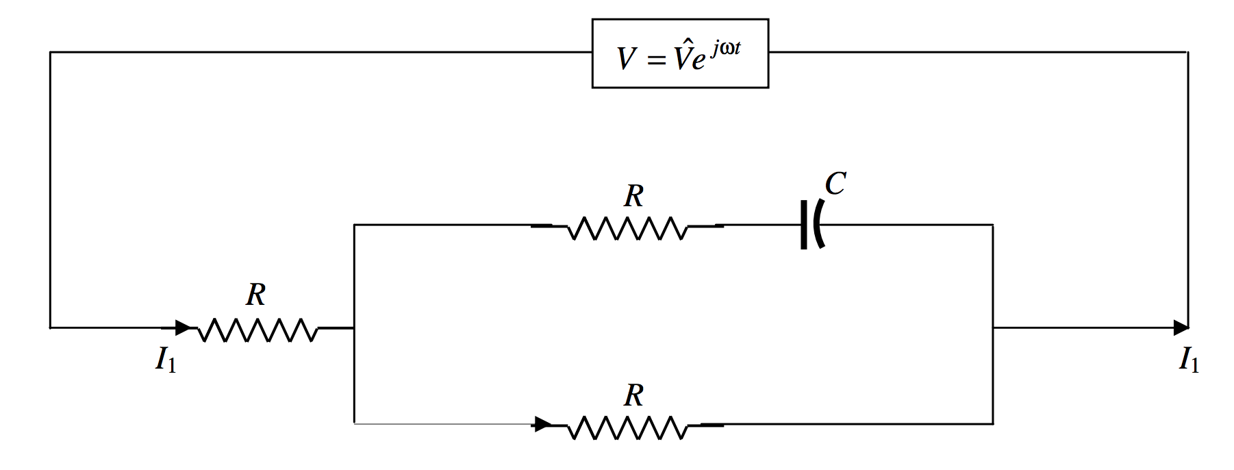
To calculate \(I_1\) we have to calculate the admittance \(Y\) of the circuit, and then we have immediately \(I_2=YV\). The impedance of \(R\) and \(C\) in series is \(R-jAR\) and so its admittance is \(\dfrac{1}{R-jaR}\). The admittance of the rectangle is therefore \(\dfrac{1}{R-jaR}+\dfrac{1}{R}=\dfrac{1}{R}\cdot \left [ \dfrac{2-ja}{1-ja}\right ]\). The impedance of the rectangle is \(R\cdot \left [ \dfrac{1-ja}{2-ja}\right ]\), and the impedance of the whole circuit is \(R\) plus this, which is \(R\cdot \left [ \dfrac{3-2ja}{2-ja}\right ]\). The admittance of the whole circuit is \(\dfrac{1}{R}\cdot \left [\dfrac{2-ja}{3-2ja}\right ]\). Multiply top and bottom by the conjugate of the denominator to obtain \(\dfrac{1}{R}\cdot \left [\dfrac{6+2a^2+ja}{9+4a^2}\right ]\). Hence \(I_1 = \dfrac{V}{R}\cdot \left [ \dfrac{6+2a^2+ja}{9+4a^2}\right ]\), which is what we obtained by the Kirchhoff method.
If you want to invent some similar problems, either as a student for practice, or as an instructor looking for homework or examination questions, you could generalize the above problem as follows.
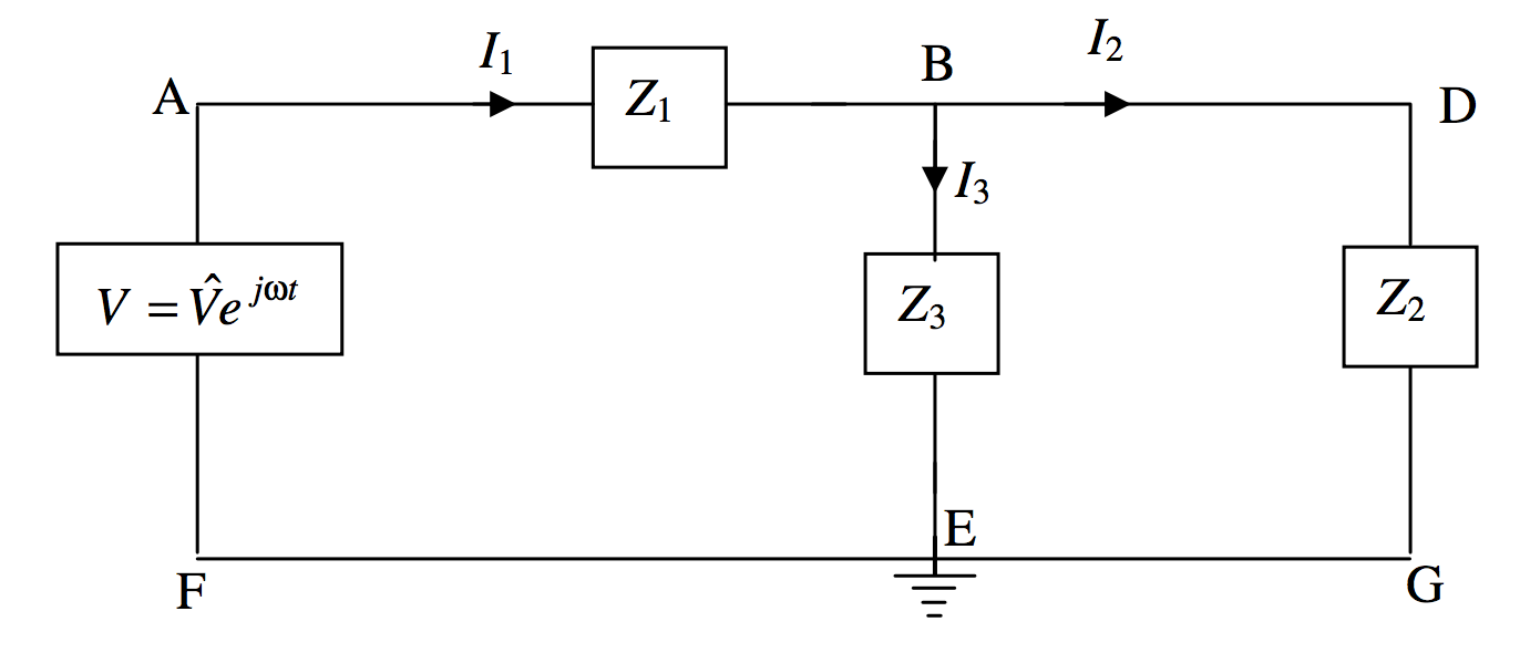
Each of the three impedances in the circuit could be various combinations of capacitors and inductors in series or in parallel, but, whatever the configuration, each could be written in the form \(R+jX\). Three Kirchhoff equations could be constructed as follows
\[\label{13.6.20}V=I_1Z_1+I_3Z_3\]
\[\label{13.6.21}V=I_1Z_1+I_2Z_2\]
\[\label{13.6.22}I_1=I_2+I_3\]
If I have done my algebra correctly, I make the solutions
\[\label{13.6.23}I_1 = \dfrac{V(Z_2+Z_3)}{Z_2Z_3+Z_3Z_1+Z_1Z_2}\]
\[\label{13.6.24}I_2 = \dfrac{VZ_3}{Z_2Z_3+Z_3Z_1+Z_1Z_2}\]
\[\label{13.6.25}I_3 = \dfrac{VZ_2}{Z_2Z_3+Z_3Z_1+Z_1Z_2}\]
Each must eventually be written in the form \(\text{Re}I+j\text{Im}I\), or \((G+jB)V\). For example, suppose that the three impedances, in ohms, are \(Z_1=2-3j,\,Z_2=4+2j,\,Z_3=3-3j\). In that case, I believe (let me know if I’m wrong, jtatum at uvic.ca) that Equation \ref{13.6.25} becomes, after manipulation, \(I_3=\dfrac{74+152j}{1429}V\). This means that \(I_3\) leads on \(V\) by 64º.0, and that the peak value of \(I_3\) is \(0.118V\text{ A}\), where \(V\) is in \(\text{V}\).
The potential at \(\text{B}\) is \(I_3Z_3\). Both of these are complex numbers and the potential at \(\text{B}\) us not in phase with \(I_3\) unless \(Z_3\)is purely resistive.
In composing a problem, you probably want all resistances and reactances to be of comparable magnitudes, say a few ohms each. As a guide, if you choose the frequency to be \(500/\pi \text{ Hz}\), so that \(\omega = 10^3 \text{ rad s}^{-1}\), and if you choose inductances to be about 10 mH and capacitances about \(100 \mu \text{F}\), your reactances will each be about \(10 \Omega\).
You can probably also compose problems with various bridge circuits, such as
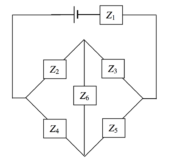
There are six independent impedances, so you’ll need six equations. Three for Kirchhoff’s second rule, to cover the complete circuit once; and three of Kirchhoff’s first rule, at three points. Good luck in solving them. Remember that, in an equation involving complex numbers, the real and imaginary parts are separately equal. And remember, as soon as a complex number appears in a denominator, multiply top and bottom with the conjugate. Alternatively, and easier, we could do what we did with a similar problem with direct currents in Section 4.12, using a delta-star transformation. We’ll try an example in Section 13.9, subsection 13.9.4.