
11.3: Propagation of Radio Waves and Thermal Emission


- Last updated
- Jun 7, 2025
- Save as PDF

( \newcommand{\kernel}{\mathrm{null}\,}\)
Multipath Propagation
Electromagnetic waves can be absorbed, refracted, and scattered as they propagate through linear media. One result of this is that beams from the same transmitter can arrive at a receiver from multiple directions simultaneously with differing delays, strengths, polarizations, and Doppler shifts. These separate phasors add constructively or destructively to yield an enhanced or diminished total response that is generally frequency dependent. Since cellular telephones are mobile and seldom have a completely unobstructed propagation path, they often exhibit strong fading and multipath effects.
Consider first the simple case where a single beam arrives via a direct path and a reflected beam with one-quarter the power of the first arrives along a reflected path that is 100λ longer. If the powers of these two beams are constant, then the total received power will fluctuate with frequency. If the voltage received for the direct beam is V_ and that of the second beam is V_/2, corresponding to quarter power, then when they are in phase the total received power is 1.52|V_|2/2R, where R is the circuit impedance. When they are 180o out of phase the power is 0.52|V_|2/2R, or one-ninth the maximum. This shift between maximum and minimum occurs each time the relative delay between the two paths changes by λ/2. Because the differential delay D is ~100λ, this represents a frequency change Δf of only one part in 200; Δf/f = λ/2D. Note that reflections can enhance or diminish the main signal, and clever antenna arrays can always compensate for the differential delays experienced from different directions so as to enhance the result.
Since cellular phones can have path differences of ~1 km at wavelengths of ~10 cm, their two-beam frequency maxima can be separated by as little as 10-4f, where f can be ~109 Hz. Fortunately this separation of 105 Hz is large compared to typical voice bandwidths. Alternatively, cellular phone signals can be coded to cover bandwidths large compared to fading bandwidths so the received signal strength is averaged over multiple frequency nulls and peaks and is therefore more stable.
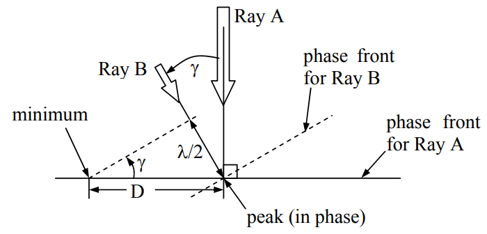
Multipath also produces nulls in space if the rays arrive from different directions. For example, if two rays A and B of wavelength λ and arrive from angles separated by a small angle γ, then the distance D between intensity maxima and minima along a line roughly perpendicular to the direction of arrival will be ~λ/(2sinγ). The geometry is sketched in Figure 11.3.1. Three or more beams can be analyzed by similar phasor addition methods. Sometimes one of the beams is reflected from a moving surface, or the transmitter or receiver are moving, so these maxima and minima can vary rapidly with time.
Normal broadcast NTSC television signals have 6-MHz bandwidth. If a metal building reflects perfectly a signal that travels a distance L further than the direct beam before the two equalstrength beams sum at the receiving antenna, how large can L be and still ensure that there are not two nulls in the 6-MHz passband between 100 and 106 MHz?
Solution
The differential path L is L/λ wavelengths long. If this number of wavelengths increases by one, then L/λ' = L/λ + 1 as λ decreases to λ'; this implies λ/λ' = 1 + λ/L = f '/f = 1.06. When the direct and reflected signals sum, the 2π phase change over this frequency band will produce one null, or almost two nulls if they fall at the band edges. Note that only the differential path length is important here. Therefore
L=λ1.06−1≅16.7λ=16.7c/f≅16.7×3×108/108=50.0meters.
Absorption, scattering, and diffraction
The terrestrial atmosphere can absorb, scatter, and refract electromagnetic radiation. The dominant gaseous absorbers at radio and microwave wavelengths are water vapor and oxygen. At submillimeter and infrared wavelengths, numerous trace gases such as ozone, NO, CO, OH, and others also become important. At wavelengths longer than 3 mm only the oxygen absorption band ~50 - 70 GHz is reasonably opaque. Horizontal attenuation at some frequencies 57-63 GHz exceeds 10 dB/km, and vertical attenuation can exceed 100 dB. The water vapor band 20-24 GHz absorbs less than 25 percent of radiation transmitted toward zenith or along a ~2-km horizontal path.
More important at low frequencies is the ionosphere, which reflects all radiation below its plasma frequency fo, as discussed in Section 9.5.3. Radio waves transmitted vertically upward at frequency f are reflected directly back if any ionospheric layer has a plasma frequency fp < f, where fp is given by (9.5.25) and is usually below 15 MHz. The ionosphere generally extends from ~70 to ~700 km altitude, with electron densities peaking ~300 km and exhibiting significant drops below ~200 km at night when solar radiation no longer ionizes the atmosphere fast enough to overcome recombination.
Above the plasma frequency fp radio waves are also perfectly reflected at an angle of reflection θr equal to the angle of incidence θi if θi exceeds the critical angle θc(f) (9.2.30) for any ionospheric layer. The critical angle
θc(f)=sin−1(εion /ε0),
where the permittivity of the ionosphere
εion (f)=ε0[1−(fp/f)2].
Since ε0>εion at any finite frequency, there exists a grazing angle of incidence θi where waves are perfectly reflected from the ionosphere at frequencies well above fp. The curvature of the earth precludes grazing incidence with θi → 90° unless the bottom surface of the ionosphere is substantially tilted. Therefore the maximum frequency at which radio waves can bounce around the world between the ionosphere and the surface of the earth is limited to ~2fp, depending on the height of the ionosphere for the frequency of interest.
The most important non-gaseous atmospheric absorbers are clouds and rain, where the latter can attenuate signals 30 dB or more. Rain is a major absorber for centimeter-wavelength satellite dishes, partly in the atmosphere and partly as the rain accumulates on the antennas. At longer wavelengths most systems have enough sensitivity to tolerate such attenuation. In comparison, clouds are usually not a problem except for through-the-air optical communication systems.
Atmospheric refraction is dominated by water vapor at radio wavelengths and by atmospheric density at optical wavelengths. These effects are not trivial. The radio sun can appear to set almost one solar diameter later on a very humid summer day (the sun emits strong radio waves too), and weak scattering from inhomogeneities in atmospheric humidity was once used as a major long-distance radio communications technique that avoided reliance on signals reflected from the ionosphere, as well as providing bandwidths of several GHz. Refraction by the ionosphere is even more extreme, and the angles of refraction can be computed using the properties of plasmas noted in Section 9.5.3 and Snell’s law (9.2.26).
It is often convenient to model urban multipath and diffractive communications links by a power law other than r-2. One common model is r-3.8, which approximates the random weaking of signals by sequences of urban obstacles as signals 1.5-5 GHz propagate further. In any study of wireless communications systems propagation effects such as these must always be considered.
Thermal Emission
A final effect impacting wireless communications systems is thermal noise arising from the environment, plus other forms of interference. Usually the thermal noise is considered interference too, but in radio astronomy and remote sensing it is the signal of interest. Thermal noise arises from electromagnetic radiation emitted by electrons colliding randomly with other particles in thermal equilibrium at temperature T. These collisions cause electrons to accelerate in random directions and therefore radiate. Thus every material object or medium radiates thermal noise provided that object or medium is coupled to the radiation field to any degree at all. Decoupled media perfectly reflect or transmit electromagnetic radiation without loss and are rare.
Thermal radiation propagating in a single-mode transmission line has intensity:
I[W/Hz]=hfehf/kT−1≅kT for hf≪kT 58(thermal intensity)
58 eδ=1+δ+δ2/2!+… for δ<<1.
Because there is a one-to-one relationship between intensity I and the corresponding brightness temperature T, the brightness temperature T[K] = I/k often replaces I because of its more natural physical significance. T is the temperature of a matched load (R = Zo) that would naturally radiate the same intensity I = kT Watts/Hz for hf << kT. This Rayleigh-Jeans approximation for I is valid at temperatures T above 50K for all frequencies f below ~100 GHz.
Thus the Thevenin equivalent circuit of a resistor at temperature T includes a voltage source producing a generally observable gaussian white voltage vTh(t) called Johnson noise. This source voltage vTh(t) radiates kTB [W] down a matched transmission line within the bandwidth B [Hz]. This Johnson noise voltage vTh(t) also divides across the Thevenin resistance R and its matched load Zo = R to produce the propagating line voltage v+(t, z=0) = vTh/2. But the radiated power is:
P+=⟨v2+⟩Zo=⟨(vTh/2)2⟩Zo=kTB [W] (thermal noise power)
Therefore within bandwidth B the root-mean-square open-circuit thermal voltage vThrms across a resistor R at temperature T is:
vThrms=√4kTBR [V](Johnson noise)
A TEM line of impedance Zo does not add any Johnson noise to that of the resistor if the line is lossless and therefore decoupled from the radiation.
Any antenna matched to its TEM transmission line therefore receives thermal noise power kTAB [W] from the environment, where TA is defined as the antenna temperature. TA is the gainweighted average of the brightness temperature TB of the environment over 4π steradians:
TA=14π∫4πTB(θ,ϕ)G(θ,ϕ)dΩ(antenna temperature)
If the entire field of view has brightness temperature TB = To, and if the antenna is lossless so that G(θ,φ) = D(θ,φ), then TA = To since ∫4πD(θ,ϕ)dΩ=4π (10.3.3).
Radio Astronomy and Remote Sensing
An antenna looking down at the earth sees a brightness temperature TB, which is the sum of thermal radiation emitted by the earth plus downward propagating power that is then reflected from the same surface:
TB=ξT+|Γ_|2T′B,]n
where the emissivity of the earth ξ=1−|Γ_|2, Γ_ is the wave reflection coefficient of the earth, and TB' is the brightness temperature of the radiation reflected from the earth into the antenna beam. The radiation from space at microwave frequencies has a brightness temperature near 2.7K arising from the "big bang" that occurred at the birth of the universe, and reaches temperatures over 7000K in the direction of the sun and certain astronomical objects, depending on frequency. The science of radio astronomy involves the study of such celestial radio waves.
The emissivity 1−|Γ_|2 of the terrestrial surface is typically 0.85-0.98 over land and ˜>0.3 over ocean. Since most communications antennas point horizontally, about half their beam intercepts the earth (~260K) and half intercepts space (~4K at microwave frequencies), so the thermal noise from the environment typically adds ~132K to the antenna temperature and total system noise.
The study of natural radio, infrared, and visible emission from the earth is called remote sensing, although one can also remotely sense biological, manufacturing, and other systems. Today many satellites in polar and geostationary orbits routinely observe the earth at tens to thousands of wavelengths across the radio and optical spectrum for meteorological and other geophysical purposes. For example, a satellite observing in the opaque 53-67 GHz oxygen resonance band can not see much lower than 70 km altitude at the very centers of the strongest spectral lines, and therefore those channels observe the temperature of the atmosphere at those high altitudes. At nearby frequencies where the atmosphere is more transparent these sensors see the air temperatures at lower altitudes. Combinations of such observations yield the temperature profile of the atmosphere all over the globe, enabling better numerical weather predictions. Channels near the centers of water vapor, ozone, and other spectral lines can similarly measure their abundance and altitude profiles for similar purposes. Channels in the more transparent bands see closer to the terrestrial surface and permit estimates to be made of rain rate, surface winds, soil moisture, and other parameters.
Communications, radioastronomy, and remote sensing systems all receive non-thermal radio interference as well. Man-made interference comes from other transmitters in the same or nearby bands, automobiles, microwave ovens, motors, power supplies, corona around power lines, and other electrical devices. Each unshielded wire in any electrical device is a small antenna that radiates. For example, computers can emit highly structured signals that reveal the state of the computation and, in special cases, even the contents of registers. Poorly shielded power supplies often radiate at very high harmonics of their fundamental operating frequencies. Fortunately, regulations increasingly restrict radio emissions from modern electrical and electronic systems. Natural non-thermal emission arises from lightning, solar bursts, the planet Jupiter, and other sources.