
5.7: Spatial Coherence and Young’s Experiment
- Page ID
- 57404
While for temporal coherence we used a Michelson interferometer, the natural choice to characterize spatial coherence is Young’s experiment, because it allows the fields in two points separated in space to interfere with each other. In Young’s experiment, a mask is used with two pinholes at the positions of the points \(P_{1}\) and \(P_{2}\) of interest. Let \(\mathbf{r}_{1}\) and \(\mathbf{r}_{2}\) be the position vectors of the two points \(P_{1}\) and \(P_{2}\), respectively. We write the field in \(P_{1}\) as a superposition of time-harmonic fields as in (5.3.6): \[U\left(\mathbf{r}_{1}, t\right)=\int A_{\omega}\left(\mathbf{r}_{1}\right) e^{-i \omega t} \mathrm{~d} \omega . \nonumber \] According to the Huygens-Fresnel principle, a time-harmonic disturbance with frequency \(\omega\) in the pinhole at \(\mathbf{r}_{1}\) causes a radiating spherical wave behind the mask, with time-harmonic field in some point \(\mathbf{r}\) given by \[A_{\omega}\left(\mathbf{r}_{1}\right) \frac{e^{-i \omega\left(t-\left|\mathbf{r}-\mathbf{r}_{1}\right| / c\right)}}{\left|\mathbf{r}-\mathbf{r}_{1}\right|} . \nonumber \]
The total field \(U_{1}(\mathbf{r}, t)\) in any point \(\mathbf{r}\) due to the pinhole at \(P_{1}\) is obtained by integrating over all frequencies: \[U_{1}(\mathbf{r}, t)=\int A_{\omega}\left(\mathbf{r}_{1}\right) \frac{e^{-i \omega\left(t-\left|\mathbf{r}-\mathbf{r}_{1}\right| / c\right)}}{\left|\mathbf{r}-\mathbf{r}_{1}\right|} \mathrm{d} \omega=\frac{U\left(\mathbf{r}_{1}, t-\left|\mathbf{r}-\mathbf{r}_{1}\right| / c\right)}{\left|\mathbf{r}-\mathbf{r}_{1}\right|} . \nonumber \]
In words, the field in \(\mathbf{r}\) at time \(t\) due to the pinhole at \(\mathbf{r}_{1}\) is proportional to the field at \(\mathbf{r}_{1}\) at the earlier time \(=\left|\mathbf{r}-\mathbf{r}_{1}\right| / c\) that it takes for the light to propagate form \(\mathbf{r}_{1}\) to \(\mathbf{r}\). The proportionality factor scales with the reciprocal distance between \(\mathbf{r}\) and \(\mathbf{r}_{1}\).
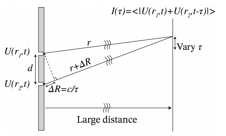
Consider the set-up shown in Figure \(\PageIndex{1}\). The fields \(U_{1}\) and \(U_{2}\) from the two pinholes at \(\mathbf{r}_{1}\) and \(\mathbf{r}_{2}\) interfere with each other in a point \(\mathbf{r}\) at a great distance. Because of the difference in propagation distance \(\Delta R=\left|\mathbf{r}-\mathbf{r}_{2}\right|-\left|\mathbf{r}-\mathbf{r}_{1}\right|\), there is a time difference \(\tau\) between the two fields when they arrive at point \(\mathbf{r}\) on the screen, given by \[\tau=\frac{\Delta R}{c} . \nonumber \]
Furthermore, because of the propagation, the amplitudes are reduced by a factor proportional to the reciprocal distance which is different for the two fields. But if the distance between the two screens is large enough, we can take these factors to be the same and then omit them. The interference pattern on the screen is then given by \[\begin{aligned} I(\tau) &=\left\langle\left|U_{1}(\mathbf{r}, t)+U_{2}(\mathbf{r}, t)\right|^{2}\right\rangle \\ &=\left\langle\left|U\left(\mathbf{r}_{1}, t-\left|\mathbf{r}-\mathbf{r}_{1}\right| \mid / c\right)+U\left(\mathbf{r}_{2}, t-\left|\mathbf{r}-\mathbf{r}_{2}\right| \mid / c\right)\right|^{2}\right\rangle \\ &=\left\langle\left|U\left(\mathbf{r}_{1}, t\right)+U\left(\mathbf{r}_{2}, t-\tau\right)\right|^{2}\right\rangle \\ &=\left\langle\left|U\left(\mathbf{r}_{1}, t\right)\right|^{2}\right\rangle+\left\langle\left|U\left(\mathbf{r}_{2}, t-\tau\right)\right|^{2}\right\rangle+2 \operatorname{Re}\left\langle U\left(\mathbf{r}_{1}, t\right) U\left(\mathbf{r}_{2}, t-\tau\right)^{*}\right\rangle . \end{aligned} \nonumber \]
We define the mutual coherence function and the intensities: \[\begin{gathered} \Gamma_{12}(\tau)=\left\langle U\left(\mathbf{r}_{1}, t\right) U\left(\mathbf{r}_{2}, t-\tau\right)^{*}\right\rangle, \\ \quad I_{1}=\left\langle\left|U\left(\mathbf{r}_{1}, t\right)\right|^{2}\right\rangle=\Gamma_{11}(0), \\ I_{2}=\left\langle\left|U\left(\mathbf{r}_{2}, t-\tau\right)\right|^{2}\right\rangle=\Gamma_{22}(0) . \end{gathered} \nonumber \]
The complex degree of mutual coherence is defined by using these intensities to normalise \(\Gamma_{12}(\tau)\) : \[\gamma_{12}(\tau)=\frac{\Gamma_{12}(\tau)}{\sqrt{\Gamma_{11}(0)} \sqrt{\Gamma_{22}(0)}}, \quad \quad \text { complex degree of mutual coherence. } \nonumber \]
The modulus of \(\gamma_{12}\) is smaller or equal than 1 (which can be proved by using Bessel’s inequality). We can now write ( \(\PageIndex{5}\) ) as \[I(\tau)=I_{1}+I_{2}+2 \sqrt{I_{1}} \sqrt{I_{2}} \operatorname{Re}\left\{\gamma_{12}(\tau)\right\} . \nonumber \]
By varying the point of observation \(\mathbf{r}\) over the screen, we can vary \(\tau\). By measuring the intensities, we can deduce the real part of \(\gamma_{12}(\tau)\). Note that \(\gamma_{12}(\tau)\) indicates the ability to form fringes.
Let us see what happens when \(U(\mathbf{r}, t)\) is a monochromatic field \[U(\mathbf{r}, t)=A(\mathbf{r}) e^{-i \omega t} . \nonumber \]
In that case \[\begin{aligned} \Gamma_{12}(\tau) &=\left\langle A\left(\mathbf{r}_{1}\right) A\left(\mathbf{r}_{2}\right)^{*} e^{-i \omega t} e^{i \omega(t-\tau)}\right\rangle \\ &=A\left(\mathbf{r}_{1}\right) A\left(\mathbf{r}_{2}\right)^{*} e^{-i \omega \tau} . \end{aligned} \nonumber \]
So we get \[\gamma_{12}(\tau)=\frac{\Gamma_{12}(\tau)}{\left|A\left(\mathbf{r}_{1}\right)\right|\left|A\left(\mathbf{r}_{2}\right)\right|}=e^{-i \omega \tau+i \varphi}, \nonumber \] where \(\varphi\) is the phase difference of \(A\left(\mathbf{r}_{2}\right)\) and \(A\left(\mathbf{r}_{1}\right)\). In this case \(\gamma_{12}\) has modulus 1 , as expected for a monochromatic field. The intensity on the screen becomes \[I(\tau)=\left|A\left(\mathbf{r}_{1}\right)\right|^{2}+\left|A\left(\mathbf{r}_{2}\right)\right|^{2}+2\left|A\left(\mathbf{r}_{1}\right)\right|\left|A\left(\mathbf{r}_{2}\right)\right| \cos (\omega \tau-\varphi) . \nonumber \]
So indeed we see interference fringes, as one would expect for a monochromatic wave. If \(\varphi=0\), then interference maxima occur for \[\omega \tau=0, \pm 2 \pi, \pm 4 \pi, \pm 6 \pi, \ldots \nonumber \]
Because \(\omega=c \frac{2 \pi}{\lambda}\), and \(\Delta R=c \tau\), we find that maxima occur when \[\Delta R=0, \pm \lambda, \pm 2 \lambda, \pm 3 \lambda, \ldots \nonumber \]
For large distance between the mask and the screen (in the Fraunhofer limit), these path length differences correspond to directions of the maxima given by the angles \(\theta_{m}\) (see Figure \(\PageIndex{1}\) ): \[\theta_{m}=\frac{\Delta R}{d}=m \frac{\lambda}{d}, \nonumber \] where \(d\) is the distance between the slits and \(m\) is an integer.
Remark. We recognise \(\Gamma_{12}(\tau)=\left\langle U\left(\mathbf{r}_{1}, t\right) U\left(\mathbf{r}_{2}, t-\tau\right)^{*}\right\rangle\) to be the cross-correlation of the two signals \(U\left(\mathbf{r}_{1}, t\right)\) and \(U\left(\mathbf{r}_{2}, t\right)\).