8.3: Boosts and Rotations
- Page ID
- 3468
\( \newcommand{\vecs}[1]{\overset { \scriptstyle \rightharpoonup} {\mathbf{#1}} } \)
\( \newcommand{\vecd}[1]{\overset{-\!-\!\rightharpoonup}{\vphantom{a}\smash {#1}}} \)
\( \newcommand{\dsum}{\displaystyle\sum\limits} \)
\( \newcommand{\dint}{\displaystyle\int\limits} \)
\( \newcommand{\dlim}{\displaystyle\lim\limits} \)
\( \newcommand{\id}{\mathrm{id}}\) \( \newcommand{\Span}{\mathrm{span}}\)
( \newcommand{\kernel}{\mathrm{null}\,}\) \( \newcommand{\range}{\mathrm{range}\,}\)
\( \newcommand{\RealPart}{\mathrm{Re}}\) \( \newcommand{\ImaginaryPart}{\mathrm{Im}}\)
\( \newcommand{\Argument}{\mathrm{Arg}}\) \( \newcommand{\norm}[1]{\| #1 \|}\)
\( \newcommand{\inner}[2]{\langle #1, #2 \rangle}\)
\( \newcommand{\Span}{\mathrm{span}}\)
\( \newcommand{\id}{\mathrm{id}}\)
\( \newcommand{\Span}{\mathrm{span}}\)
\( \newcommand{\kernel}{\mathrm{null}\,}\)
\( \newcommand{\range}{\mathrm{range}\,}\)
\( \newcommand{\RealPart}{\mathrm{Re}}\)
\( \newcommand{\ImaginaryPart}{\mathrm{Im}}\)
\( \newcommand{\Argument}{\mathrm{Arg}}\)
\( \newcommand{\norm}[1]{\| #1 \|}\)
\( \newcommand{\inner}[2]{\langle #1, #2 \rangle}\)
\( \newcommand{\Span}{\mathrm{span}}\) \( \newcommand{\AA}{\unicode[.8,0]{x212B}}\)
\( \newcommand{\vectorA}[1]{\vec{#1}} % arrow\)
\( \newcommand{\vectorAt}[1]{\vec{\text{#1}}} % arrow\)
\( \newcommand{\vectorB}[1]{\overset { \scriptstyle \rightharpoonup} {\mathbf{#1}} } \)
\( \newcommand{\vectorC}[1]{\textbf{#1}} \)
\( \newcommand{\vectorD}[1]{\overrightarrow{#1}} \)
\( \newcommand{\vectorDt}[1]{\overrightarrow{\text{#1}}} \)
\( \newcommand{\vectE}[1]{\overset{-\!-\!\rightharpoonup}{\vphantom{a}\smash{\mathbf {#1}}}} \)
\( \newcommand{\vecs}[1]{\overset { \scriptstyle \rightharpoonup} {\mathbf{#1}} } \)
\(\newcommand{\longvect}{\overrightarrow}\)
\( \newcommand{\vecd}[1]{\overset{-\!-\!\rightharpoonup}{\vphantom{a}\smash {#1}}} \)
\(\newcommand{\avec}{\mathbf a}\) \(\newcommand{\bvec}{\mathbf b}\) \(\newcommand{\cvec}{\mathbf c}\) \(\newcommand{\dvec}{\mathbf d}\) \(\newcommand{\dtil}{\widetilde{\mathbf d}}\) \(\newcommand{\evec}{\mathbf e}\) \(\newcommand{\fvec}{\mathbf f}\) \(\newcommand{\nvec}{\mathbf n}\) \(\newcommand{\pvec}{\mathbf p}\) \(\newcommand{\qvec}{\mathbf q}\) \(\newcommand{\svec}{\mathbf s}\) \(\newcommand{\tvec}{\mathbf t}\) \(\newcommand{\uvec}{\mathbf u}\) \(\newcommand{\vvec}{\mathbf v}\) \(\newcommand{\wvec}{\mathbf w}\) \(\newcommand{\xvec}{\mathbf x}\) \(\newcommand{\yvec}{\mathbf y}\) \(\newcommand{\zvec}{\mathbf z}\) \(\newcommand{\rvec}{\mathbf r}\) \(\newcommand{\mvec}{\mathbf m}\) \(\newcommand{\zerovec}{\mathbf 0}\) \(\newcommand{\onevec}{\mathbf 1}\) \(\newcommand{\real}{\mathbb R}\) \(\newcommand{\twovec}[2]{\left[\begin{array}{r}#1 \\ #2 \end{array}\right]}\) \(\newcommand{\ctwovec}[2]{\left[\begin{array}{c}#1 \\ #2 \end{array}\right]}\) \(\newcommand{\threevec}[3]{\left[\begin{array}{r}#1 \\ #2 \\ #3 \end{array}\right]}\) \(\newcommand{\cthreevec}[3]{\left[\begin{array}{c}#1 \\ #2 \\ #3 \end{array}\right]}\) \(\newcommand{\fourvec}[4]{\left[\begin{array}{r}#1 \\ #2 \\ #3 \\ #4 \end{array}\right]}\) \(\newcommand{\cfourvec}[4]{\left[\begin{array}{c}#1 \\ #2 \\ #3 \\ #4 \end{array}\right]}\) \(\newcommand{\fivevec}[5]{\left[\begin{array}{r}#1 \\ #2 \\ #3 \\ #4 \\ #5 \\ \end{array}\right]}\) \(\newcommand{\cfivevec}[5]{\left[\begin{array}{c}#1 \\ #2 \\ #3 \\ #4 \\ #5 \\ \end{array}\right]}\) \(\newcommand{\mattwo}[4]{\left[\begin{array}{rr}#1 \amp #2 \\ #3 \amp #4 \\ \end{array}\right]}\) \(\newcommand{\laspan}[1]{\text{Span}\{#1\}}\) \(\newcommand{\bcal}{\cal B}\) \(\newcommand{\ccal}{\cal C}\) \(\newcommand{\scal}{\cal S}\) \(\newcommand{\wcal}{\cal W}\) \(\newcommand{\ecal}{\cal E}\) \(\newcommand{\coords}[2]{\left\{#1\right\}_{#2}}\) \(\newcommand{\gray}[1]{\color{gray}{#1}}\) \(\newcommand{\lgray}[1]{\color{lightgray}{#1}}\) \(\newcommand{\rank}{\operatorname{rank}}\) \(\newcommand{\row}{\text{Row}}\) \(\newcommand{\col}{\text{Col}}\) \(\renewcommand{\row}{\text{Row}}\) \(\newcommand{\nul}{\text{Nul}}\) \(\newcommand{\var}{\text{Var}}\) \(\newcommand{\corr}{\text{corr}}\) \(\newcommand{\len}[1]{\left|#1\right|}\) \(\newcommand{\bbar}{\overline{\bvec}}\) \(\newcommand{\bhat}{\widehat{\bvec}}\) \(\newcommand{\bperp}{\bvec^\perp}\) \(\newcommand{\xhat}{\widehat{\xvec}}\) \(\newcommand{\vhat}{\widehat{\vvec}}\) \(\newcommand{\uhat}{\widehat{\uvec}}\) \(\newcommand{\what}{\widehat{\wvec}}\) \(\newcommand{\Sighat}{\widehat{\Sigma}}\) \(\newcommand{\lt}{<}\) \(\newcommand{\gt}{>}\) \(\newcommand{\amp}{&}\) \(\definecolor{fillinmathshade}{gray}{0.9}\)Learning Objectives
- Explain rotations and boosts
A relative of mine fell in love. She and her boyfriend bought a house in the suburbs and had a baby. They think they’ll get married at some later point. An engineer by training, she says she doesn’t want to get hung up on the “order of operations.” For some mathematical operations, the order doesn’t matter: \(5 + 7\) is the same as \(7 + 5\).
Rotations
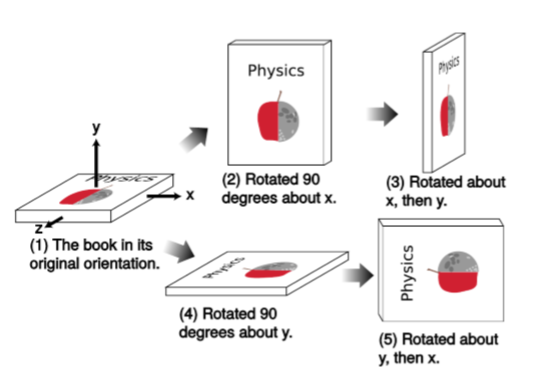
Fgure \(\PageIndex{1}\) shows that the order of operations does matter for rotations. Rotating around the \(x\) axis and then \(y\) produces a different result than \(y\) followed by \(x\). We say that rotations are noncommutative. This is why, in Newtonian mechanics, we don’t have an angular displacement vector \(∆θ\); vectors are supposed to be additive, and vector addition is commutative. For small rotations, however, the discrepancy caused by choosing one order of operations rather than the other becomes small (of order \(θ^2\)), so we can define an infinitesimal displacement vector \(dθ\), whose direction is given by the right-hand rule, and an angular velocity \(ω = dθ/dt\).

As an example of how this works out for small rotations, let’s take the vector
\[(0,0,1)\]
and apply the operations shown in Figure \(\PageIndex{1}\), but with rotations of only \(θ = 0.1\) radians rather than \(90\) degrees. Rotation by this angle about the \(x\) axis is given by the transformation
\[(x,y,z) → (x,y \cos θ - z \sin θ,y \sin θ + z \cos θ)\]
and applying this to the original vector gives this:
\[(0.00000,-0.09983,0.99500)\; \; \; (\text{after }x)\]
After a further rotation by the same angle, this time about the \(y\) axis, we have
\[(0.09933,-0.09983,0.99003) \; \; \; (\text{after }x, \text{then }y)\]
Starting over from the original vector in Figure \(\PageIndex{1.1}\) and doing the operations in the opposite order gives these results:
\[(0.09983,0.00000,0.99500) \; \; \; (\text{after }y)\]
\[(0.09983,-0.09933,0.99003) \; \; \; (\text{after }y, \text{then }x)\]
The discrepancy between (\(\PageIndex{1.3}\)) and (\(\PageIndex{1.5}\)) is a rotation by very nearly \(0.005\) radians in the \(xy\) plane. As claimed, this is on the order of \(θ^2\) (in fact, it’s almost exactly \(θ^2/2\)). A single example can never prove anything, but this is an example of the general rule that rotations along different axes don’t commute, and for small angles the discrepancy is a rotation in the plane defined by the two axes, with a magnitude whose maximum size is on the order of \(θ^2\).
Boosts
Something similar happens for boosts. In \(3 + 1\) dimensions, we start with the vector
\[(0,1,0,0)\]
pointing along the \(x\) axis. A Lorentz boost with \(v = 0.1\) (Equation 1.4.1) in the \(x\) direction gives
\[(0.10050,1.00504,0.00000,0.00000) \; \; \; (\text{after }x)\]
and a second boost, now in the \(y\) direction, produces this:
\[(0.10101,1.00504,0.01010,0.00000) \; \; \; (\text{after }x, \text{then }y)\]
Starting over from (\(\PageIndex{6}\)) and doing the boosts in the opposite order, we have
\[(0.00000,1.00000,0.00000,0.00000) \; \; \; (\text{after }y)\]
\[(0.10050,1.00504,0.00000,0.00000) \; \; \; (\text{after }y, \text{then }x)\]
The discrepancy between (\(\PageIndex{8}\)) and (\(\PageIndex{10}\)) is a rotation in the \(xy\) plane by very nearly \(0.01\) radians. This is an example of a more general fact, which is that boosts along different axes don’t commute, and for small angles the discrepancy is a rotation in the plane defined by the two boosts, with a magnitude whose maximum size is on the order of \(v^2\), in units of radians.
Thomas Precession
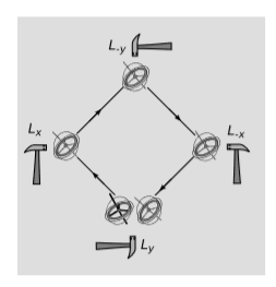
Figure \(\PageIndex{2}\) shows the most important physical consequence of all this. The gyroscope is sent around the perimeter of a square, with impulses provided by hammer taps at the corners. Each impulse can be modeled as a Lorentz boost, notated, e.g., \(L_x\) for a boost in the \(x\) direction. The series of four operations can be written as \(L_yL_xL_{-y}L_{-x}\), using the notational convention that the first operation applied is the one on the right side of the list. If boosts were commutative, we could swap the two operations in the middle of the list, giving \(L_yL_{-y}L_xL_{-x}\). The \(L_x\) would undo the \(L_{-x}\), and the \(L_y\) would undo the \(L_{-y}\). But boosts aren’t commutative, so the vector representing the orientation of the gyroscope is rotated in the \(xy\) plane. This effect is called the Thomas precession, after Llewellyn Thomas (1903-1992). Thomas precession is a purely relativistic effect, since a Newtonian gyroscope does not change its axis of rotation unless subjected to a torque; if the boosts are accomplished by forces that act at the gyroscope’s center, then there is no nonrelativistic explanation for the effect.

Clearly we should see the same effect if the jerky motion in Fgure \(\PageIndex{2}\) was replaced by uniform circular motion, and something similar should happen in any case in which a spinning object experiences an external force. In the limit of low velocities, the general expression for the angular velocity of the precession is \(Ω = a×v\), and in the case of circular motion, \(Ω = \frac{1}{2}v^2ω\), where \(ω\) is the frequency of the circular motion.
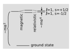
If we want to see this precession effect in real life, we should look for a system in which both \(v\) and \(a\) are large. An atom is such a system. The Bohr model, introduced in 1913, marked the first quantitatively successful, if conceptually muddled, description of the atomic energy levels of hydrogen. Continuing to take \(c = 1\), the over-all scale of the energies was calculated to be proportional to \(mα^2\), where \(m\) is the mass of the electron, and \(α\) is the fine structure constant, defined earlier. At higher resolution, each excited energy level is found to be split into several sub-levels. The transitions among these close-lying states are in the millimeter region of the microwave spectrum. The energy scale of this fine structure is \(∼ mα^4\). This is down by a factor of \(α^2\) compared to the visible-light transitions, hence the name of the constant. Uhlenbeck and Goudsmit showed in 1926 that a splitting on this order of magnitude was to be expected due to the magnetic interaction between the proton and the electron’s magnetic moment, oriented along its spin. The effect they calculated, however, was too big by a factor of two.

The explanation of the mysterious factor of two had in fact been implicit in a 1916 calculation by Willem de Sitter, one of the first applications of general relativity. De Sitter treated the earth-moon system as a gyroscope, and found the precession of its axis of rotation, which was partly due to the curvature of spacetime and partly due to the type of rotation described earlier in this section. The effect on the motion of the moon was noncumulative, and was only about one meter, which was much too small to be measured at the time. In 1927, however, Thomas applied similar reasoning to the hydrogen atom, with the electron’s spin vector playing the role of gyroscope. Since the electron’s spin is \(\hbar /2\), the energy splitting is \(\pm (\hbar /2) \Omega\), depending on whether the electron’s spin is in the same direction as its orbital motion, or in the opposite direction. This is less than the atom’s gross energy scale \(\hbar \omega\) by a factor of \(v^2/2\), which is \(∼ α^2\). The Thomas precession cancels out half of the magnetic effect, bringing theory in agreement with experiment.
Uhlenbeck later recalled: “...when I first heard about [the Thomas precession], it seemed unbelievable that a relativistic effect could give a factor of 2 instead of something of order \(v/c\)... Even the cognoscenti of relativity theory (Einstein included!) were quite surprised.”


