
17.4: The Electric Field Revisited
- Page ID
- 14546

\( \newcommand{\vecs}[1]{\overset { \scriptstyle \rightharpoonup} {\mathbf{#1}} } \)
\( \newcommand{\vecd}[1]{\overset{-\!-\!\rightharpoonup}{\vphantom{a}\smash {#1}}} \)
\( \newcommand{\dsum}{\displaystyle\sum\limits} \)
\( \newcommand{\dint}{\displaystyle\int\limits} \)
\( \newcommand{\dlim}{\displaystyle\lim\limits} \)
\( \newcommand{\id}{\mathrm{id}}\) \( \newcommand{\Span}{\mathrm{span}}\)
( \newcommand{\kernel}{\mathrm{null}\,}\) \( \newcommand{\range}{\mathrm{range}\,}\)
\( \newcommand{\RealPart}{\mathrm{Re}}\) \( \newcommand{\ImaginaryPart}{\mathrm{Im}}\)
\( \newcommand{\Argument}{\mathrm{Arg}}\) \( \newcommand{\norm}[1]{\| #1 \|}\)
\( \newcommand{\inner}[2]{\langle #1, #2 \rangle}\)
\( \newcommand{\Span}{\mathrm{span}}\)
\( \newcommand{\id}{\mathrm{id}}\)
\( \newcommand{\Span}{\mathrm{span}}\)
\( \newcommand{\kernel}{\mathrm{null}\,}\)
\( \newcommand{\range}{\mathrm{range}\,}\)
\( \newcommand{\RealPart}{\mathrm{Re}}\)
\( \newcommand{\ImaginaryPart}{\mathrm{Im}}\)
\( \newcommand{\Argument}{\mathrm{Arg}}\)
\( \newcommand{\norm}[1]{\| #1 \|}\)
\( \newcommand{\inner}[2]{\langle #1, #2 \rangle}\)
\( \newcommand{\Span}{\mathrm{span}}\) \( \newcommand{\AA}{\unicode[.8,0]{x212B}}\)
\( \newcommand{\vectorA}[1]{\vec{#1}} % arrow\)
\( \newcommand{\vectorAt}[1]{\vec{\text{#1}}} % arrow\)
\( \newcommand{\vectorB}[1]{\overset { \scriptstyle \rightharpoonup} {\mathbf{#1}} } \)
\( \newcommand{\vectorC}[1]{\textbf{#1}} \)
\( \newcommand{\vectorD}[1]{\overrightarrow{#1}} \)
\( \newcommand{\vectorDt}[1]{\overrightarrow{\text{#1}}} \)
\( \newcommand{\vectE}[1]{\overset{-\!-\!\rightharpoonup}{\vphantom{a}\smash{\mathbf {#1}}}} \)
\( \newcommand{\vecs}[1]{\overset { \scriptstyle \rightharpoonup} {\mathbf{#1}} } \)
\(\newcommand{\longvect}{\overrightarrow}\)
\( \newcommand{\vecd}[1]{\overset{-\!-\!\rightharpoonup}{\vphantom{a}\smash {#1}}} \)
\(\newcommand{\avec}{\mathbf a}\) \(\newcommand{\bvec}{\mathbf b}\) \(\newcommand{\cvec}{\mathbf c}\) \(\newcommand{\dvec}{\mathbf d}\) \(\newcommand{\dtil}{\widetilde{\mathbf d}}\) \(\newcommand{\evec}{\mathbf e}\) \(\newcommand{\fvec}{\mathbf f}\) \(\newcommand{\nvec}{\mathbf n}\) \(\newcommand{\pvec}{\mathbf p}\) \(\newcommand{\qvec}{\mathbf q}\) \(\newcommand{\svec}{\mathbf s}\) \(\newcommand{\tvec}{\mathbf t}\) \(\newcommand{\uvec}{\mathbf u}\) \(\newcommand{\vvec}{\mathbf v}\) \(\newcommand{\wvec}{\mathbf w}\) \(\newcommand{\xvec}{\mathbf x}\) \(\newcommand{\yvec}{\mathbf y}\) \(\newcommand{\zvec}{\mathbf z}\) \(\newcommand{\rvec}{\mathbf r}\) \(\newcommand{\mvec}{\mathbf m}\) \(\newcommand{\zerovec}{\mathbf 0}\) \(\newcommand{\onevec}{\mathbf 1}\) \(\newcommand{\real}{\mathbb R}\) \(\newcommand{\twovec}[2]{\left[\begin{array}{r}#1 \\ #2 \end{array}\right]}\) \(\newcommand{\ctwovec}[2]{\left[\begin{array}{c}#1 \\ #2 \end{array}\right]}\) \(\newcommand{\threevec}[3]{\left[\begin{array}{r}#1 \\ #2 \\ #3 \end{array}\right]}\) \(\newcommand{\cthreevec}[3]{\left[\begin{array}{c}#1 \\ #2 \\ #3 \end{array}\right]}\) \(\newcommand{\fourvec}[4]{\left[\begin{array}{r}#1 \\ #2 \\ #3 \\ #4 \end{array}\right]}\) \(\newcommand{\cfourvec}[4]{\left[\begin{array}{c}#1 \\ #2 \\ #3 \\ #4 \end{array}\right]}\) \(\newcommand{\fivevec}[5]{\left[\begin{array}{r}#1 \\ #2 \\ #3 \\ #4 \\ #5 \\ \end{array}\right]}\) \(\newcommand{\cfivevec}[5]{\left[\begin{array}{c}#1 \\ #2 \\ #3 \\ #4 \\ #5 \\ \end{array}\right]}\) \(\newcommand{\mattwo}[4]{\left[\begin{array}{rr}#1 \amp #2 \\ #3 \amp #4 \\ \end{array}\right]}\) \(\newcommand{\laspan}[1]{\text{Span}\{#1\}}\) \(\newcommand{\bcal}{\cal B}\) \(\newcommand{\ccal}{\cal C}\) \(\newcommand{\scal}{\cal S}\) \(\newcommand{\wcal}{\cal W}\) \(\newcommand{\ecal}{\cal E}\) \(\newcommand{\coords}[2]{\left\{#1\right\}_{#2}}\) \(\newcommand{\gray}[1]{\color{gray}{#1}}\) \(\newcommand{\lgray}[1]{\color{lightgray}{#1}}\) \(\newcommand{\rank}{\operatorname{rank}}\) \(\newcommand{\row}{\text{Row}}\) \(\newcommand{\col}{\text{Col}}\) \(\renewcommand{\row}{\text{Row}}\) \(\newcommand{\nul}{\text{Nul}}\) \(\newcommand{\var}{\text{Var}}\) \(\newcommand{\corr}{\text{corr}}\) \(\newcommand{\len}[1]{\left|#1\right|}\) \(\newcommand{\bbar}{\overline{\bvec}}\) \(\newcommand{\bhat}{\widehat{\bvec}}\) \(\newcommand{\bperp}{\bvec^\perp}\) \(\newcommand{\xhat}{\widehat{\xvec}}\) \(\newcommand{\vhat}{\widehat{\vvec}}\) \(\newcommand{\uhat}{\widehat{\uvec}}\) \(\newcommand{\what}{\widehat{\wvec}}\) \(\newcommand{\Sighat}{\widehat{\Sigma}}\) \(\newcommand{\lt}{<}\) \(\newcommand{\gt}{>}\) \(\newcommand{\amp}{&}\) \(\definecolor{fillinmathshade}{gray}{0.9}\)learning objectives
- Identify law that can be used to calculate an electric field created by a point charge
The electric field of a point charge is, like any electric field, a vector field that represents the effect that the point charge has on other charges around it. The effect is felt as a force, and when charged particles are not in motion, this force is known as the electrostatic force. The electrostatic force is, much like gravity, a force that acts at a distance. Therefore, we rationalize this action at a distance by saying that charges create fields around them that have effects on other charges.
Given a point charge, or a particle of infinitesimal size that contains a certain charge, electric field lines emanate radially in all directions. If the charge is positive, field lines point radially away from it; if the charge is negative, field lines point radially towards it.
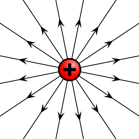
Electric field of positive point charge: The electric field of a positively charged particle points radially away from the charge.
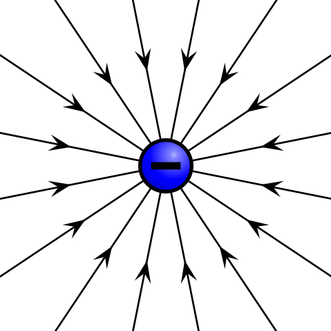
Electric field of negative point charge: The electric field of a negatively charged particle points radially toward the particle.
The reason for these directions can be seen in the derivation of the electric field of a point charge. Let’s first take a look at the definition of the electric field of a point particle:
\[\vec { \mathrm { E } } = \frac { 1 } { 4 \pi \epsilon _ { \mathrm { o } } } \frac { \mathrm { q } } { \mathrm { r } ^ { 2 } } \hat { \mathbf { r } } = \mathrm { k } \frac { \mathrm { q } } { \mathrm { r } ^ { 2 } } \hat { \mathbf { r } }\]
The above equation is defined in radial coordinates, which can be seen in. The constant k is a result of simply combining the constants together, and q is the charge of the particle creating the electric field. This charge is either positive or negative. If the charge is positive, as shown above, the electric field will be pointing in a positive radial direction from the charge q (away from the charge).
As a demonstration of this phenomenon, if we now place another positive charge, Q (called the test charge), at some radial distance, R, away from the original particle, the test charge will feel a force given by
\[\vec { \mathrm { F } } = \mathrm { Q } \vec { \mathrm { E } } = Q \frac { 1 } { 4 \pi \epsilon _ { \mathrm { o } } } \frac { \mathrm { q } } { \mathrm { R } ^ { 2 } } \hat { \mathbf { r } }\]
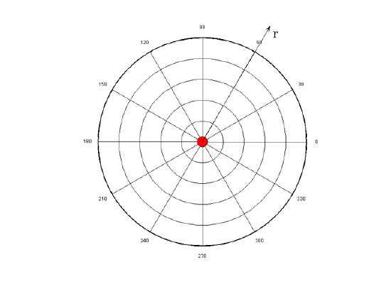
Radial Coordinate System: The electric field of a point charge is defined in radial coordinates. The positive r direction points away from the origin, and the negative r direction points toward the origin. The electric field of a point charge is symmetric with respect to the θ direction.
The thing to keep in mind is that the force above is acting on the test charge Q, in the positive radial direction as defined by the original charge q. This means that because the charges are both positive and will repel one another, the force on the test charge points away from the original charge.
If the test charge were negative, the force felt on that charge would be:
\[\vec { \mathbf { F } } = \mathbf { Q } \vec { \mathrm { E } } = - Q \frac { 1 } { 4 \pi \epsilon _ { 0 } } \frac { \mathrm { q } } { \mathrm { R } ^ { 2 } } \hat { \mathbf { r } }\]
Notice that this points in the negative ^rr^ direction, which is toward the original charge. This makes sense because opposite charges attract, and the force on the test charge will tend to push it toward the original positive charge creating the field. The above mathematical description of the electric field of a point charge is known as Coulomb ‘s law.
Superposition of Fields
The resultant of multiple electric fields acting on the same point is the sum of the strength of each field’s applied force at that point.
learning objectives
- Formulate the superposition principle for a linear system
As vector fields, electric fields obey the superposition principle. This principle states that for all linear systems, the net response to multiple stimuli at a given place and time is equal to the sum of the responses that would have resulted from each stimulus individually.
Possible stimuli include but are not limited to: numbers, functions, vectors, vector fields, and time-varying signals. It should be noted that the superposition principle is applicable to any linear system, including algebraic equations, linear differential equations, and systems of equations of the aforementioned forms.
For example, if forces A and B are constant and simultaneously act upon an object, illustrated as O in, the resultant force will be the sum of forces A and B. Vector addition is commutative, so whether adding A to B or B to A makes no difference on the resultant vector; this is also the case for subtraction of vectors.
Vector addition: Forces a and b act upon an object at point O. Their sum is commutative, and results in a resultant vector c.
Electric fields are continuous fields of vectors, so at a given point, one can find the forces that several fields will apply to a test charge and add them to find the resultant. To do this, first find the component vectors of force applied by each field in each of the orthogonal axes. This can be done using trigonometric functions. Then once the component vectors are found, add the components in each axis that are applied by the combined electric fields.
This is one only form of solution. An overall resultant vector can be found by using the Pythagorean theorem to find the resultant (the hypotenuse of the triangle created with applied forces as legs) and the angle with respect to a given axis by equating the inverse tangent of the angle to the ratio of the forces of the adjacent and opposite legs.
Electric Field Lines: Multiple Charges
Electric fields created by multiple charges interact as do any other type of vector field; their forces can be summed.
learning objectives
- Calculate the resultant force of the multiple electric charges on a test charge
Thus far, we have looked at electric field lines pertaining to isolated point charges. But what if another charge is introduced? Each will have its own electric field, and the two fields will interact.
When modeling the electric fields of multiple charges, it’s important to take into consideration the sign and magnitude of each charge. Such models are not meant to be absolute, but must be self-consistent. For example, the number field of lines should be proportional to the value of the charge that gives rise to them. This means that if charges q1 (with a +1 value) q2 (+2 charge) and q3 (+3 charge) are in the same field, one can connect 4, 8, and 12 field lines, respectively, to the charges. One could also choose to connect 3, 6, and 9 field lines, respectively, to q1, q2, and q3; what matters is that the number of lines are related to the charge values by the same proportionality constant. Field lines should always point away from positive charges and towards negative charge.
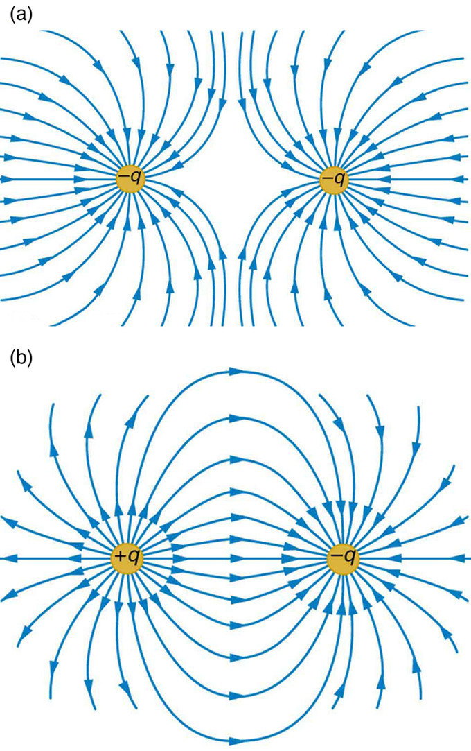
Field lines between like and unlike charges: Example a shows how the electric field is weak between like charges (the concentration of field lines is low between them). Example b, by contrast, has a strong field between the charges, as exhibited by the high concentration of field lines connecting them.
If there are opposite charges in consideration, connect one to the other with field lines. If charges are the same, do not connect them in any way.
The strength of the electric field depends proportionally upon the separation of the field lines. More field lines per unit area perpendicular to the lines means a stronger field. It should also be noted that at any point, the direction of the electric field will be tangent to the field line.
Determining net force on a test charge
As vector fields, electric fields exhibit properties typical of vectors and thus can be added to one another at any point of interest. Thus, given charges q1, q2,… qn, one can find their resultant force on a test charge at a certain point using vector addition: adding the component vectors in each direction and using the inverse tangent function to solve for the angle of the resultant relative to a given axis.
Parallel-Plate Capacitor
A parallel-plate capacitor is an electrical component used to store energy in an electric field between two charged, flat surfaces.
learning objectives
- Describe general structure of a capacitor
Overview
A capacitor is an electrical component used to store energy in an electric field. Capacitors can take many forms, but all involve two conductors separated by a dielectric material. For the purpose of this atom, we will focus on parallel-plate capacitors.
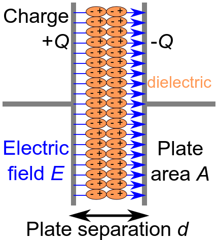
Diagram of a Parallel-Plate Capacitor: Charges in the dielectric material line up to oppose the charges of each plate of the capacitor. An electric field is created between the plates of the capacitor as charge builds on each plate.
Capacitance
All capacitors collect charge on the two, separate conductive surfaces; one side is positive and the other negative. An electric field is created as charge builds on the opposite surfaces, storing energy. The dielectric between the conductors is meant to act as an insulator, preventing charge from bridging the gap between the two plates. Such dielectrics are commonly composed of glass, air, paper, or empty space (a vacuum). In practice, dielectrics do not act as perfect insulators, and permit a small amount of leakage current to pass through them.
Capacitors are limited in their ability to prevent charge flow from one conductive surface to the other; their ability to hold charge is measured in Farads (F), which are defined as 1 ampere-second per volt, one joule per square volt and one Coulomb per volt, among other ways.
For a parallel-plate capacitor, capacitance (C) is related to dielectric permittivity (ε), surface area (A), and separation between the plates (d):
\[\mathrm { C } = \dfrac { \epsilon \mathrm { A } } { \mathrm { d } }\]
Voltage (V) of a capacitor is related to distance between the plates, dielectric permittivity, conductor surface area, and charge (Q) on the plates:
\[\mathrm { V } = \dfrac { Q \mathrm { d } } { \epsilon \mathrm { A } }\]
Depending on the dielectric strength (Eds) and distance (d) between plates, a capacitor will “break” at a certain voltage (Vbd). This is calculated by:
\[\mathrm { V } _ { \mathrm { bd } } = \mathrm { E } _ { \mathrm { ds } } \mathrm { d } \]
Parallel Plates and Equipotential Lines: A brief overview of parallel plates and equipotential lines from the viewpoint of electrostatics.
Electric Fields and Conductors
Electric fields in the presence of conductors have several unique and not necessarily intuitive properties.
learning objectives
- Describe unique properties expressed by electric fields in the presence of conductors
An electric field, like other fields (e.g., gravitational or magnetic), is a vector field that surrounds an object. Electric fields are found around electric charges and help determine the direction and magnitude of force the charge exerts on a nearby charged particle. It measures units of force exerted per unit of charge, and its SI units are N/C.
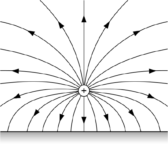
Field Lines Created by a Point Charge: Lines around the positive charge represent the electric field it creates.
Electrical conductors are materials in which internal charges can move freely. Therefore, they can facilitate the flow of charge, or current. When a conductor is placed in the presence of an electric field, it exhibits some interesting properties:
- There is no electric field inside a charged conductor. A charged conductor at electrostatic equilibrium will contain charges only on its outer surface and will have no net electric field within itself. This is because all the charges in such a conductor will symmetrically oppose other charges within the conductor, causing the net result to sum to 0.
- Charged surfaces align themselves perpendicularly relative to electric fields. Provided a conductor is at electrostatic equilibrium, the electric field upon the surface will be aligned perpendicularly with respect to that surface. If there were a nonzero parallel component of the electric field, with respect to any charge on the surface of a conductor, that charge would exert a force and would move. If the conductor is at equilibrium, such a force cannot exist, and therefore the direction of the electric field must be completely perpendicular to the surface.
- Curvature on the surface of a conductor allows for increased charge concentration. Charge will not necessarily distribute itself evenly over the surface of a conductor. If the surface of the conductor is flat, charge will be very evenly distributed. But as the surface becomes more sharply curved, charge can be found more densely packed in areas, even if the conductor is at electrostatic equilibrium. Charges on a curved surface repel one another less strongly than they would on a smooth surface. This is because, based on how the charges are positioned, much of the repulsion the charges exert is in the direction away from the surface of the conductor, not along its surface. And it is harder for charges to be pushed off a surface than along it. Therefore, the repulsion between charges on a curved surface is weaker.
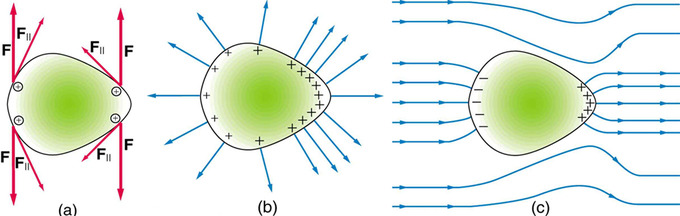
Electrical Charge at a Sharp Point of a Conductor: Repulsive forces towards the more sharply curved surface on the right aim more outward than along the surface of the conductor.
Conductors and Fields in Static Equilibrium
In the presence of charge or an electric field, the charges in a conductor will redistribute until they reach static equilibrium.
learning objectives
- Describe behavior of charges in a conductor in the presence of charge or an electric field and under static equilibrium
Conductors are materials in which charges can move freely. If conductors are exposed to charge or an electric field, their internal charges will rearrange rapidly. For example, if a neutral conductor comes into contact with a rod containing a negative charge, some of that negative charge will transfer to the conductor at the point of contact. But the charge will not stay local to the contact point — it will distribute itself evenly over the surface of the conductor. Once the charges are redistributed, the conductor is in a state of electrostatic equilibrium. It should be noted that the distribution of charges depends on the shape of the conductor and that static equilibrium may not necessarily involve an even distribution of charges, which tend to aggregate in higher concentrations around sharp points. This is explained in.

Electrical Charge at a Sharp Point of a Conductor: Forces between like charges at either end of the conductor are identical, but the components of the forces parallel to the surfaces are different. The component parallel to the surface is greatest on the flattest surface and therefore moves charges away from one another more freely. This explains the difference in concentration of charge on flat vs. pointed areas of a conductor.
Similarly, if a conductor is placed in an electric field, the charges within the conductor will move until the field is perpendicular to the surface of the conductor. Negative charges in the conductor will align themselves towards the positive end of the electric field, leaving positive charges at the negative end of the field. The conductor thus becomes polarized, with the electric field becoming stronger near the conductor but disintegrating inside it. This occurrence is similar to that observed in a Faraday cage, which is an enclosure made of a conducting material that shields the inside from an external electric charge or field or shields the outside from an internal electric charge or field.
Key Points
- The electric field is a vector field around a charged particle. It represents the force that other charged particles would feel if placed near the particle creating the electric field.
- Given a point charge, or a particle of infinitesimal size, that contains a certain charge, electric field lines emanate from equally in all radial directions.
- If the point charge is positive, field lines point away from it; if the charge is negative, field lines point toward it.
- The superposition principle states that for all linear systems, the net response to multiple stimuli at a given place and time is equal to the sum of the responses that would have been caused by each stimulus individually.
- Possible stimuli include but are not limited to numbers, functions, vectors, vector fields, and time-varying signals.
- The superposition principle is applicable to any linear system, including algebraic equations, linear differential equations, and systems of equations of the aforementioned forms.
- Electric fields are continuous fields of vectors, so at a given point, one can find the forces that several fields will apply to a test charge and add them to find the resultant.
- When multiple electric charges interact, their resultant force on a test charge can be calculated using vector addition.
- If there are opposite charges in consideration, connect one to the other with field lines. If charges are the same, do not connect them in any way.
- When modeling the electric fields of multiple charges, take into consideration the sign and magnitude of each charge. The number of field lines should be proportional to the value of the charge that gives rise to them.
- Capacitors can take many forms, but all involve two conductors separated by a dielectric material.
- All capacitors collect charge on the two, separate conductive surfaces; one side is positive and the other negative. An electric field is created as charge builds on the opposite surfaces, storing energy. The dielectric acts as an insulator, isolating the charged surfaces.
- The ability of capacitors to hold charge is measured in Farads (F). Capacitors will typically allow a small leakage of current through the dielectric, but after a certain voltage, the entire capacitor breaks down as the dielectric becomes a conductor.
- There is no electric field inside a charged conductor. This is because charges, which are located on the surface of the conductor, symmetrically oppose one another and sum to 0 in all locations.
- Charged surfaces align themselves perpendicularly relative to electric fields to achieve electrostatic equilibrium. If charges are not distributed as such, they will exert net force upon one another, which will move them. In such an instance, the charges will not be at static equilibrium.
- Curvature on the surface of a field allows for increased charge concentration. Much of the repulsion charges exert is in the direction moving away from the surface of the conductor, rather than along its surface. Charges thus push one another more weakly along the surface of a curved conductor.
- The presence of charge or an electric field will force charges in a conductor to redistribute along the conductor’s surface until static equilibrium is achieved.
- At static equilibrium, charge will be more concentrated in sharp, pointy areas of conductors than elsewhere.
- At static equilibrium, the inside of a conductor will be entirely shielded from an external electric field.
Key Terms
- coulomb’s law: the mathematical equation calculating the electrostatic force vector between two charged particles
- vector field: a construction in which each point in a Euclidean space is associated with a vector; a function whose range is a vector space
- orthogonal: Of two objects, at right angles; perpendicular to each other.
- superposition principle: The principle that a linear combination of two or more solutions of an equation is itself a solution; it is a feature of many physical laws.
- vector: A directed quantity, one with both magnitude and direction; the between two points.
- capacitor: An electronic component capable of storing an electric charge, especially one consisting of two conductors separated by a dielectric.
- dielectric: An electrically insulating or nonconducting material considered for its electric susceptibility (i.e., its property of polarization when exposed to an external electric field).
- conductor: A material which contains movable electric charges.
- equilibrium: The state of a body at rest or in uniform motion, the resultant of all forces on which is zero.
- static equilibrium: the physical state in which all components of a system are at rest and the net force is equal to zero throughout the system
LICENSES AND ATTRIBUTIONS
CC LICENSED CONTENT, SHARED PREVIOUSLY
- Curation and Revision. Provided by: Boundless.com. License: CC BY-SA: Attribution-ShareAlike
CC LICENSED CONTENT, SPECIFIC ATTRIBUTION
- vector field. Provided by: Wiktionary. Located at: en.wiktionary.org/wiki/vector_field. License: CC BY-SA: Attribution-ShareAlike
- Electric field. Provided by: Wikipedia. Located at: en.Wikipedia.org/wiki/Electric_field. License: CC BY-SA: Attribution-ShareAlike
- Coulomb's law. Provided by: Wikipedia. Located at: en.Wikipedia.org/wiki/Coulomb's_law. License: CC BY-SA: Attribution-ShareAlike
- 480px-VFPt_plus_thumb.svg.png. Provided by: Wikimedia. Located at: commons.wikimedia.org/wiki/File:VFPt_plus_thumb.svg. License: CC BY-SA: Attribution-ShareAlike
- 480px-VFPt_minus_thumb.svg.png. Provided by: Wikimedia. Located at: commons.wikimedia.org/wiki/File:VFPt_minus_thumb.svg. License: CC BY-SA: Attribution-ShareAlike
- Boundless. Provided by: Amazon Web Services. Located at: s3.amazonaws.com/figures.boundless.com/51225257e4b0c14bf4651470/radialCoords.png. License: Public Domain: No Known Copyright
- Superposition principle. Provided by: Wikipedia. Located at: en.Wikipedia.org/wiki/Superposition_principle. License: CC BY-SA: Attribution-ShareAlike
- orthogonal. Provided by: Wiktionary. Located at: en.wiktionary.org/wiki/orthogonal. License: CC BY-SA: Attribution-ShareAlike
- vector. Provided by: Wiktionary. Located at: en.wiktionary.org/wiki/vector. License: CC BY-SA: Attribution-ShareAlike
- superposition principle. Provided by: Wiktionary. Located at: en.wiktionary.org/wiki/superposition_principle. License: CC BY-SA: Attribution-ShareAlike
- 480px-VFPt_plus_thumb.svg.png. Provided by: Wikimedia. Located at: commons.wikimedia.org/wiki/File:VFPt_plus_thumb.svg. License: CC BY-SA: Attribution-ShareAlike
- 480px-VFPt_minus_thumb.svg.png. Provided by: Wikimedia. Located at: commons.wikimedia.org/wiki/File:VFPt_minus_thumb.svg. License: CC BY-SA: Attribution-ShareAlike
- Boundless. Provided by: Amazon Web Services. Located at: s3.amazonaws.com/figures.boundless.com/51225257e4b0c14bf4651470/radialCoords.png. License: Public Domain: No Known Copyright
- Sunil Kumar Singh, Vector Addition. December 29, 2012. Provided by: OpenStax CNX. Located at: http://cnx.org/content/m13601/latest/. License: CC BY: Attribution
- OpenStax College, College Physics. September 17, 2013. Provided by: OpenStax CNX. Located at: http://cnx.org/content/m42312/latest/?collection=col11406/latest. License: CC BY: Attribution
- vector. Provided by: Wiktionary. Located at: en.wiktionary.org/wiki/vector. License: CC BY-SA: Attribution-ShareAlike
- 480px-VFPt_plus_thumb.svg.png. Provided by: Wikimedia. Located at: commons.wikimedia.org/wiki/File:VFPt_plus_thumb.svg. License: CC BY-SA: Attribution-ShareAlike
- 480px-VFPt_minus_thumb.svg.png. Provided by: Wikimedia. Located at: commons.wikimedia.org/wiki/File:VFPt_minus_thumb.svg. License: CC BY-SA: Attribution-ShareAlike
- Boundless. Provided by: Amazon Web Services. Located at: s3.amazonaws.com/figures.boundless.com/51225257e4b0c14bf4651470/radialCoords.png. License: Public Domain: No Known Copyright
- Sunil Kumar Singh, Vector Addition. December 29, 2012. Provided by: OpenStax CNX. Located at: http://cnx.org/content/m13601/latest/. License: CC BY: Attribution
- OpenStax College, College Physics. December 29, 2012. Provided by: OpenStax CNX. Located at: http://cnx.org/content/m42312/latest/?collection=col11406/latest. License: CC BY: Attribution
- Capacitor. Provided by: Wikipedia. Located at: en.Wikipedia.org/wiki/Capacitor. License: CC BY-SA: Attribution-ShareAlike
- dielectric. Provided by: Wiktionary. Located at: en.wiktionary.org/wiki/dielectric. License: CC BY-SA: Attribution-ShareAlike
- capacitor. Provided by: Wiktionary. Located at: en.wiktionary.org/wiki/capacitor. License: CC BY-SA: Attribution-ShareAlike
- conductor. Provided by: Wikipedia. Located at: en.Wikipedia.org/wiki/conductor. License: CC BY-SA: Attribution-ShareAlike
- 480px-VFPt_plus_thumb.svg.png. Provided by: Wikimedia. Located at: commons.wikimedia.org/wiki/File:VFPt_plus_thumb.svg. License: CC BY-SA: Attribution-ShareAlike
- 480px-VFPt_minus_thumb.svg.png. Provided by: Wikimedia. Located at: commons.wikimedia.org/wiki/File:VFPt_minus_thumb.svg. License: CC BY-SA: Attribution-ShareAlike
- Boundless. Provided by: Amazon Web Services. Located at: s3.amazonaws.com/figures.boundless.com/51225257e4b0c14bf4651470/radialCoords.png. License: Public Domain: No Known Copyright
- Sunil Kumar Singh, Vector Addition. December 29, 2012. Provided by: OpenStax CNX. Located at: http://cnx.org/content/m13601/latest/. License: CC BY: Attribution
- OpenStax College, College Physics. December 29, 2012. Provided by: OpenStax CNX. Located at: http://cnx.org/content/m42312/latest/?collection=col11406/latest. License: CC BY: Attribution
- Parallel Plates and Equipotential Lines. Located at: http://www.youtube.com/watch?v=EJ910SiVha0. License: Public Domain: No Known Copyright. License Terms: Standard YouTube license
- Capacitor schematic with dielectric. Provided by: Wikipedia. Located at: en.Wikipedia.org/wiki/File:Capacitor_schematic_with_dielectric.svg. License: CC BY-SA: Attribution-ShareAlike
- vector field. Provided by: Wiktionary. Located at: en.wiktionary.org/wiki/vector_field. License: CC BY-SA: Attribution-ShareAlike
- Electrical conductor. Provided by: Wikipedia. Located at: en.Wikipedia.org/wiki/Electrical_conductor. License: CC BY-SA: Attribution-ShareAlike
- Electric field. Provided by: Wikipedia. Located at: en.Wikipedia.org/wiki/Electric_field. License: CC BY-SA: Attribution-ShareAlike
- equilibrium. Provided by: Wiktionary. Located at: en.wiktionary.org/wiki/equilibrium. License: CC BY-SA: Attribution-ShareAlike
- 480px-VFPt_plus_thumb.svg.png. Provided by: Wikimedia. Located at: commons.wikimedia.org/wiki/File:VFPt_plus_thumb.svg. License: CC BY-SA: Attribution-ShareAlike
- 480px-VFPt_minus_thumb.svg.png. Provided by: Wikimedia. Located at: commons.wikimedia.org/wiki/File:VFPt_minus_thumb.svg. License: CC BY-SA: Attribution-ShareAlike
- Boundless. Provided by: Amazon Web Services. Located at: s3.amazonaws.com/figures.boundless.com/51225257e4b0c14bf4651470/radialCoords.png. License: Public Domain: No Known Copyright
- Sunil Kumar Singh, Vector Addition. December 29, 2012. Provided by: OpenStax CNX. Located at: http://cnx.org/content/m13601/latest/. License: CC BY: Attribution
- OpenStax College, College Physics. December 29, 2012. Provided by: OpenStax CNX. Located at: http://cnx.org/content/m42312/latest/?collection=col11406/latest. License: CC BY: Attribution
- Parallel Plates and Equipotential Lines. Located at: http://www.youtube.com/watch?v=EJ910SiVha0. License: Public Domain: No Known Copyright. License Terms: Standard YouTube license
- Capacitor schematic with dielectric. Provided by: Wikipedia. Located at: en.Wikipedia.org/wiki/File:Capacitor_schematic_with_dielectric.svg. License: CC BY-SA: Attribution-ShareAlike
- Field lines. Provided by: Wikipedia. Located at: en.Wikipedia.org/wiki/File:Field_lines.svg. License: CC BY-SA: Attribution-ShareAlike
- OpenStax College, College Physics. December 28, 2012. Provided by: OpenStax CNX. Located at: http://cnx.org/content/m42317/latest/?collection=col11406/latest. License: CC BY: Attribution
- static equilibrium. Provided by: Wiktionary. Located at: en.wiktionary.org/wiki/static_equilibrium. License: CC BY-SA: Attribution-ShareAlike
- OpenStax College, College Physics. September 18, 2013. Provided by: OpenStax CNX. Located at: http://cnx.org/content/m42317/latest/?collection=col11406/latest. License: CC BY: Attribution
- 480px-VFPt_plus_thumb.svg.png. Provided by: Wikimedia. Located at: commons.wikimedia.org/wiki/File:VFPt_plus_thumb.svg. License: CC BY-SA: Attribution-ShareAlike
- 480px-VFPt_minus_thumb.svg.png. Provided by: Wikimedia. Located at: commons.wikimedia.org/wiki/File:VFPt_minus_thumb.svg. License: CC BY-SA: Attribution-ShareAlike
- Boundless. Provided by: Amazon Web Services. Located at: s3.amazonaws.com/figures.boundless.com/51225257e4b0c14bf4651470/radialCoords.png. License: Public Domain: No Known Copyright
- Sunil Kumar Singh, Vector Addition. December 29, 2012. Provided by: OpenStax CNX. Located at: http://cnx.org/content/m13601/latest/. License: CC BY: Attribution
- OpenStax College, College Physics. December 29, 2012. Provided by: OpenStax CNX. Located at: http://cnx.org/content/m42312/latest/?collection=col11406/latest. License: CC BY: Attribution
- Parallel Plates and Equipotential Lines. Located at: http://www.youtube.com/watch?v=EJ910SiVha0. License: Public Domain: No Known Copyright. License Terms: Standard YouTube license
- Capacitor schematic with dielectric. Provided by: Wikipedia. Located at: http://en.Wikipedia.org/wiki/File:Capacitor_schematic_with_dielectric.svg. License: CC BY-SA: Attribution-ShareAlike
- Field lines. Provided by: Wikipedia. Located at: en.Wikipedia.org/wiki/File:Field_lines.svg. License: CC BY-SA: Attribution-ShareAlike
- OpenStax College, College Physics. December 28, 2012. Provided by: OpenStax CNX. Located at: http://cnx.org/content/m42317/latest/?collection=col11406/latest. License: CC BY: Attribution
- OpenStax College, College Physics. December 28, 2012. Provided by: OpenStax CNX. Located at: http://cnx.org/content/m42317/latest/?collection=col11406/latest. License: CC BY: Attribution