
20.5: RC Circuits
- Page ID
- 14568
")
\( \newcommand{\vecs}[1]{\overset { \scriptstyle \rightharpoonup} {\mathbf{#1}} } \)
\( \newcommand{\vecd}[1]{\overset{-\!-\!\rightharpoonup}{\vphantom{a}\smash {#1}}} \)
\( \newcommand{\dsum}{\displaystyle\sum\limits} \)
\( \newcommand{\dint}{\displaystyle\int\limits} \)
\( \newcommand{\dlim}{\displaystyle\lim\limits} \)
\( \newcommand{\id}{\mathrm{id}}\) \( \newcommand{\Span}{\mathrm{span}}\)
( \newcommand{\kernel}{\mathrm{null}\,}\) \( \newcommand{\range}{\mathrm{range}\,}\)
\( \newcommand{\RealPart}{\mathrm{Re}}\) \( \newcommand{\ImaginaryPart}{\mathrm{Im}}\)
\( \newcommand{\Argument}{\mathrm{Arg}}\) \( \newcommand{\norm}[1]{\| #1 \|}\)
\( \newcommand{\inner}[2]{\langle #1, #2 \rangle}\)
\( \newcommand{\Span}{\mathrm{span}}\)
\( \newcommand{\id}{\mathrm{id}}\)
\( \newcommand{\Span}{\mathrm{span}}\)
\( \newcommand{\kernel}{\mathrm{null}\,}\)
\( \newcommand{\range}{\mathrm{range}\,}\)
\( \newcommand{\RealPart}{\mathrm{Re}}\)
\( \newcommand{\ImaginaryPart}{\mathrm{Im}}\)
\( \newcommand{\Argument}{\mathrm{Arg}}\)
\( \newcommand{\norm}[1]{\| #1 \|}\)
\( \newcommand{\inner}[2]{\langle #1, #2 \rangle}\)
\( \newcommand{\Span}{\mathrm{span}}\) \( \newcommand{\AA}{\unicode[.8,0]{x212B}}\)
\( \newcommand{\vectorA}[1]{\vec{#1}} % arrow\)
\( \newcommand{\vectorAt}[1]{\vec{\text{#1}}} % arrow\)
\( \newcommand{\vectorB}[1]{\overset { \scriptstyle \rightharpoonup} {\mathbf{#1}} } \)
\( \newcommand{\vectorC}[1]{\textbf{#1}} \)
\( \newcommand{\vectorD}[1]{\overrightarrow{#1}} \)
\( \newcommand{\vectorDt}[1]{\overrightarrow{\text{#1}}} \)
\( \newcommand{\vectE}[1]{\overset{-\!-\!\rightharpoonup}{\vphantom{a}\smash{\mathbf {#1}}}} \)
\( \newcommand{\vecs}[1]{\overset { \scriptstyle \rightharpoonup} {\mathbf{#1}} } \)
\(\newcommand{\longvect}{\overrightarrow}\)
\( \newcommand{\vecd}[1]{\overset{-\!-\!\rightharpoonup}{\vphantom{a}\smash {#1}}} \)
\(\newcommand{\avec}{\mathbf a}\) \(\newcommand{\bvec}{\mathbf b}\) \(\newcommand{\cvec}{\mathbf c}\) \(\newcommand{\dvec}{\mathbf d}\) \(\newcommand{\dtil}{\widetilde{\mathbf d}}\) \(\newcommand{\evec}{\mathbf e}\) \(\newcommand{\fvec}{\mathbf f}\) \(\newcommand{\nvec}{\mathbf n}\) \(\newcommand{\pvec}{\mathbf p}\) \(\newcommand{\qvec}{\mathbf q}\) \(\newcommand{\svec}{\mathbf s}\) \(\newcommand{\tvec}{\mathbf t}\) \(\newcommand{\uvec}{\mathbf u}\) \(\newcommand{\vvec}{\mathbf v}\) \(\newcommand{\wvec}{\mathbf w}\) \(\newcommand{\xvec}{\mathbf x}\) \(\newcommand{\yvec}{\mathbf y}\) \(\newcommand{\zvec}{\mathbf z}\) \(\newcommand{\rvec}{\mathbf r}\) \(\newcommand{\mvec}{\mathbf m}\) \(\newcommand{\zerovec}{\mathbf 0}\) \(\newcommand{\onevec}{\mathbf 1}\) \(\newcommand{\real}{\mathbb R}\) \(\newcommand{\twovec}[2]{\left[\begin{array}{r}#1 \\ #2 \end{array}\right]}\) \(\newcommand{\ctwovec}[2]{\left[\begin{array}{c}#1 \\ #2 \end{array}\right]}\) \(\newcommand{\threevec}[3]{\left[\begin{array}{r}#1 \\ #2 \\ #3 \end{array}\right]}\) \(\newcommand{\cthreevec}[3]{\left[\begin{array}{c}#1 \\ #2 \\ #3 \end{array}\right]}\) \(\newcommand{\fourvec}[4]{\left[\begin{array}{r}#1 \\ #2 \\ #3 \\ #4 \end{array}\right]}\) \(\newcommand{\cfourvec}[4]{\left[\begin{array}{c}#1 \\ #2 \\ #3 \\ #4 \end{array}\right]}\) \(\newcommand{\fivevec}[5]{\left[\begin{array}{r}#1 \\ #2 \\ #3 \\ #4 \\ #5 \\ \end{array}\right]}\) \(\newcommand{\cfivevec}[5]{\left[\begin{array}{c}#1 \\ #2 \\ #3 \\ #4 \\ #5 \\ \end{array}\right]}\) \(\newcommand{\mattwo}[4]{\left[\begin{array}{rr}#1 \amp #2 \\ #3 \amp #4 \\ \end{array}\right]}\) \(\newcommand{\laspan}[1]{\text{Span}\{#1\}}\) \(\newcommand{\bcal}{\cal B}\) \(\newcommand{\ccal}{\cal C}\) \(\newcommand{\scal}{\cal S}\) \(\newcommand{\wcal}{\cal W}\) \(\newcommand{\ecal}{\cal E}\) \(\newcommand{\coords}[2]{\left\{#1\right\}_{#2}}\) \(\newcommand{\gray}[1]{\color{gray}{#1}}\) \(\newcommand{\lgray}[1]{\color{lightgray}{#1}}\) \(\newcommand{\rank}{\operatorname{rank}}\) \(\newcommand{\row}{\text{Row}}\) \(\newcommand{\col}{\text{Col}}\) \(\renewcommand{\row}{\text{Row}}\) \(\newcommand{\nul}{\text{Nul}}\) \(\newcommand{\var}{\text{Var}}\) \(\newcommand{\corr}{\text{corr}}\) \(\newcommand{\len}[1]{\left|#1\right|}\) \(\newcommand{\bbar}{\overline{\bvec}}\) \(\newcommand{\bhat}{\widehat{\bvec}}\) \(\newcommand{\bperp}{\bvec^\perp}\) \(\newcommand{\xhat}{\widehat{\xvec}}\) \(\newcommand{\vhat}{\widehat{\vvec}}\) \(\newcommand{\uhat}{\widehat{\uvec}}\) \(\newcommand{\what}{\widehat{\wvec}}\) \(\newcommand{\Sighat}{\widehat{\Sigma}}\) \(\newcommand{\lt}{<}\) \(\newcommand{\gt}{>}\) \(\newcommand{\amp}{&}\) \(\definecolor{fillinmathshade}{gray}{0.9}\)learning objectives
- Describe the components and function of an RC circut, noting especially the time-dependence of the capacitor’s charge
An RC circuit is one containing a resistor R and a capacitor C. The capacitor is an electrical component that houses electric charge. In this Atom, we will study how a series RC circuit behaves when connected to a DC voltage source. (In subsequent Atoms, we will study its AC behavior. )
Charging
Fig 1 shows a simple RC circuit that employs a DC voltage source. The capacitor is initially uncharged. As soon as the switch is closed, current flows to and from the initially uncharged capacitor. As charge increases on the capacitor plates, there is increasing opposition to the flow of charge by the repulsion of like charges on each plate.
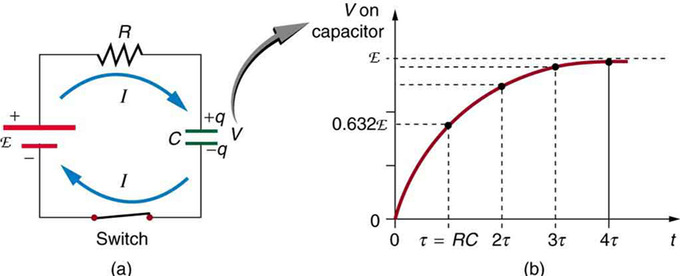
Charging an RC Circuit: (a) An RC circuit with an initially uncharged capacitor. Current flows in the direction shown as soon as the switch is closed. Mutual repulsion of like charges in the capacitor progressively slows the flow as the capacitor is charged, stopping the current when the capacitor is fully charged and Q=C⋅emf. (b) A graph of voltage across the capacitor versus time, with the switch closing at time t=0. (Note that in the two parts of the figure, the capital script E stands for emf, q stands for the charge stored on the capacitor, and τ is the RC time constant. )
In terms of voltage, across the capacitor voltage is given by Vc=Q/C, where Q is the amount of charge stored on each plate and C is the capacitance. This voltage opposes the battery, growing from zero to the maximum emf when fully charged. Thus, the current decreases from its initial value of I0=emf/R to zero as the voltage on the capacitor reaches the same value as the emf. When there is no current, there is no IR drop, so the voltage on the capacitor must then equal the emf of the voltage source.
Initially, voltage on the capacitor is zero and rises rapidly at first since the initial current is a maximum. Fig 1 (b) shows a graph of capacitor voltage versus time (t) starting when the switch is closed at t=0. The voltage approaches emf asymptotically since the closer it gets to emf the less current flows. The equation for voltage versus time when charging a capacitor C through a resistor R, is:
\[\mathrm { V } ( \mathrm { t } ) = \operatorname { emf } \left( 1 - \mathrm { e } ^ { \mathrm { t } / \mathrm { RC } } \right)\]
where V(t) is the voltage across the capacitor and emf is equal to the emf of the DC voltage source. (The exact form can be derived by solving a linear differential equation describing the RC circuit, but this is slightly beyond the scope of this Atom. ) Note that the unit of RC is second. We define the time constant τ for an RC circuit as \(\tau = \mathrm { R } \mathrm { C }\). τ shows how quickly the circuit charges or discharges.
Discharging
Discharging a capacitor through a resistor proceeds in a similar fashion, as illustrates. Initially, the current is I0=V0/R, driven by the initial voltage V0 on the capacitor. As the voltage decreases, the current and hence the rate of discharge decreases, implying another exponential formula for V. Using calculus, the voltage V on a capacitor C being discharged through a resistor R is found to be
\[\mathrm { V } ( \mathrm { t } ) = \mathrm { V } _ { 0 } \mathrm { e } ^ { - \mathrm { t } / \mathrm { RC } }\]
Impedance
Impedance is the measure of the opposition that a circuit presents to the passage of a current when a voltage is applied.
learning objectives
- Express the relationship between the impedance, the resistance, and the capacitance of a series RC circuit in a form of equation
Rather than solving the differential equation relating to circuits that contain resistors and capacitors, we can imagine all sources in the circuit are complex exponentials having the same frequency. This technique is useful in solving problems in which phase relationship is important. The phase of the complex impedance is the phase shift by which the current is ahead of the voltage.
Complex Analysis
For an RC circuit in, the AC source driving the circuit is given as:
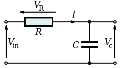
Series RC Circuit: Series RC circuit.
\[\mathrm { v } _ { \mathrm { in } } ( \mathrm { t } ) = \mathrm { Ve } ^ { \mathrm { j } \omega t }\]
where V is the amplitude of the AC voltage, j is the imaginary unit (j2=-1), and ωω is the angular frequency of the AC source. Two things to note:
- We use lower case alphabets for voltages and sources to represent that they are alternating (i.e., we use vin(t) instead of Vin(t)).
- The imaginary unit is given the symbol “j”, not the usual “i”. “i” is reserved for alternating currents.
Complex Impedance
The advantage of assuming sources take this form is that all voltages and currents in the circuit are also complex exponentials (having the same frequency as the source). To appreciate the reason for this, we can investigate how each circuit element behaves when either the voltage or current is a complex exponential. For the resistor, \(\mathrm { v } = \mathrm { R } \mathrm { i }\). From our voltage given above, \(\mathrm { i } = \frac { \mathrm { V } } { \mathrm { R } } \mathrm { e } ^ { \mathrm { j } \omega t } \) . Thus the resistor’s voltage is a complex, as is the current with an amplitude \(\mathrm { I } = \frac { \mathrm { V } } { \mathrm { R } }\). For a capacitor, \(\mathrm { i } = \mathrm { C } \frac { \mathrm { dv } } { \mathrm { dt } }\). Letting the voltage be a complex exponential we have \(\mathrm{i=jωCVe^{jωt}}\). The amplitude of this complex exponential is \(\mathrm{I=jωCV}\).
The major consequence of assuming complex exponential voltage and currents is that the ratio \(\mathrm{Z = \frac { V } { I }}\) for rather than depending on time each element depends on source frequency. This quantity is known as the element’s (complex) impedance. The magnitude of the complex impedance is the ratio of the voltage amplitude to the current amplitude. Just like resistance in DC cases, impedance is the measure of the opposition that a circuit presents to the passage of a current when a voltage is applied. The impedance of a resistor is R, while that of a capacitor (C) is \(\mathrm{\frac { 1 } { j \omega C }}\). In the case of the circuit in, to find the complex impedance of the RC circuit, we add the impedance of the two components, just as with two resistors in series: \(\mathrm { Z } = \mathrm { R } + \frac { 1 } { \mathrm { j } \omega \mathrm { C } }\).
Finding Real Currents and Voltages
Since \(\mathrm { e } ^ { \mathrm { j } \omega t } = \cos ( \omega \mathrm { t } ) + \mathrm { j } \sin ( \omega \mathrm { t } )\), to find the real currents and voltages we simply need to take the real part of the i(t) and v(t). The (real value) impedance is the real part of the complex impedance Z. For a series RC circuit, we get \(\mathrm { Z } = \sqrt { \mathrm { R } ^ { 2 } + \left( \frac { 1 } { \omega C } \right) ^ { 2 } }\). We see that the amplitude of the current will be \( \frac{\mathrm { V }}{ \mathrm { Z }} = \frac { \mathrm { V } } { \sqrt { \mathrm { R } ^ { 2 } + \left( \frac { 1 } { \omega C } \right) ^ { 2 } } }\).
Phase Angle and Power Factor
In a series RC circuit connected to an AC voltage source, voltage and current maintain a phase difference.
learning objectives
- Compare the currents in the resistor and capacitor in a series RC circuit connected to an AC voltage source
Phase Angle
Impedance is an AC (alternating current) analogue to resistance in a DC circuit. As we studied in a previously Atom (“Impedance”), current, voltage and impedance in an RC circuit are related by an AC version of Ohm ‘s law: \(\mathrm{I=\frac{V}{Z}}\), where I and V are peak current and peak voltage respectively, and Z is the impedance of the circuit.
In a series RC circuit connected to an AC voltage source as shown in, conservation of charge requires current be the same in each part of the circuit at all times. Therefore we can say: the currents in the resistor and capacitor are equal and in phase. (We will represent instantaneous current as i(t). )

Series RC Circuit: Series RC circuit.
On the other hand, because the total voltage should be equal to the sum of voltages on the resistor and capacitor, so we have:
\[\left.\begin{aligned} \mathrm { v } ( \mathrm { t } ) & = \mathrm { v } _ { \mathrm { R } } ( \mathrm { t } ) + \mathrm { v } _ { \mathrm { C } } ( \mathrm { t } ) \\ & = \mathrm { i } ( \mathrm { t } ) \mathrm { R } + \mathrm { i } ( \mathrm { t } ) \frac { 1 } { \mathrm { j } \omega C } \\ & = \mathrm { i } ( \mathrm { t } ) \left( \mathrm { R } + \frac { 1 } { \mathrm { j } \omega C } \right) \end{aligned} \right.\]
where ωω is the angular frequency of the AC voltage source and j is the imaginary unit; j2=-1. Since the complex number \(\mathrm { Z } = \mathrm { R } + \frac { 1 } { \mathrm { j } \omega C } = \sqrt { \mathrm { R } ^ { 2 } + \left( \frac { 1 } { \omega \mathrm{C} } \right) ^ { 2 } } \mathrm { e } ^ { \mathrm { j } \phi }\) has a phase angle \(ϕ\) that satisfies \(\cos \phi = \frac { \mathrm { R } } { \sqrt { \mathrm { R } ^ { 2 } + \left( \frac { 1 } { \omega \mathrm{ C} } \right) ^ { 2 } } }\),
we notice that voltage \(\mathrm{v(t)}\) and current \(\mathrm{i(t)}\) has a phase difference of \(ϕ\).
For \(\mathrm{R=0, ϕ=90^∘}\). As learned from the preceding series of Atoms—the voltage across the capacitor VC follows the current by one-fourth of a cycle (or 90º).
Power Factor
Because voltage and current are out of phase, power dissipated by the circuit is not equal to: (peak voltage) times (peak current). The fact that source voltage and current are out of phase affects the power delivered to the circuit. It can be shown that the average power is IrmsVrmscosϕ, where Irms and Vrms are the root mean square (rms) averages of the current and voltage, respectively. For this reason, cosϕ is called the power factor, which can range from 0 to 1.
Key Points
- In an RC circuit connected to a DC voltage source, the current decreases from its initial value of I0=emf/R to zero as the voltage on the capacitor reaches the same value as the emf.
- In an RC circuit connected to a DC voltage source, voltage on the capacitor is initially zero and rises rapidly at first since the initial current is a maximum: \( \mathrm { V } ( \mathrm { t } ) = \operatorname { emf } \left( 1 - \mathrm { e } ^ { \mathrm{t} / \mathrm { RC } } \right)\).
- The time constant τ for an RC circuit is defined to be RC. It’s unit is in seconds and shows how quickly the circuit charges or discharges.
- The advantage of assuming that sources have complex exponential form is that all voltages and currents in the circuit are also complex exponentials, having the same frequency as the source.
- The major consequence of assuming complex exponential voltage and currents is that the ratio (Z = V/I) for each element does not depend on time, but does depend on source frequency.
- For a series RC circuit, the impedance is given as \( \mathrm { Z } = \sqrt { \mathrm { R } ^ { 2 } + \left( \frac { 1 } { \omega \mathrm{C} } \right) ^ { 2 } }\).
- In a series RC circuit connected to an AC voltage source, the currents in the resistor and capacitor are equal and in phase.
- In a series RC circuit connected to an AC voltage source, the total voltage should be equal to the sum of voltages on the resistor and capacitor.
- In a series RC circuit connected to an AC voltage source, voltage and current have a phase difference of \(ϕ\), where \(\cos \phi = \frac { \mathrm { R } } { \sqrt { \mathrm { R } ^ { 2 } + \left( \frac { 1 } { \omega \mathrm{C} } \right) ^ { 2 } } }\). cosϕ is called the power factor.
Key Terms
- DC: Direct current; the unidirectional flow of electric charge.
- capacitor: An electronic component capable of storing an electric charge, especially one consisting of two conductors separated by a dielectric.
- differential equation: An equation involving the derivatives of a function.
- impedance: A measure of the opposition to the flow of an alternating current in a circuit; the aggregation of its resistance, inductive and capacitive reactance. Represented by the symbol Z.
- resistor: An electric component that transmits current in direct proportion to the voltage across it.
- alternating current: (AC)—An electric current in which the direction of flow of the electrons reverses periodically having an average of zero, with positive and negative values (with a frequency of 50 Hz in Europe, 60 Hz in the US, 400 Hz for airport lighting, and some others); especially such a current produced by a rotating generator or alternator.
- rms: Root mean square: a statistical measure of the magnitude of a varying quantity.
LICENSES AND ATTRIBUTIONS
CC LICENSED CONTENT, SHARED PREVIOUSLY
- Curation and Revision. Provided by: Boundless.com. License: CC BY-SA: Attribution-ShareAlike
CC LICENSED CONTENT, SPECIFIC ATTRIBUTION
- DC. Provided by: Wikipedia. Located at: en.Wikipedia.org/wiki/DC. License: CC BY-SA: Attribution-ShareAlike
- OpenStax College, DC Circuits Containing Resistors and Capacitors. September 17, 2013. Provided by: OpenStax CNX. Located at: http://cnx.org/content/m42363/latest/. License: CC BY: Attribution
- capacitor. Provided by: Wiktionary. Located at: en.wiktionary.org/wiki/capacitor. License: CC BY-SA: Attribution-ShareAlike
- differential equation. Provided by: Wiktionary. Located at: en.wiktionary.org/wiki/differential_equation. License: CC BY-SA: Attribution-ShareAlike
- OpenStax College, DC Circuits Containing Resistors and Capacitors. February 15, 2013. Provided by: OpenStax CNX. Located at: http://cnx.org/content/m42363/latest/. License: CC BY: Attribution
- Electrical impedance. Provided by: Wikipedia. Located at: en.Wikipedia.org/wiki/Electrical_impedance. License: CC BY-SA: Attribution-ShareAlike
- Don Johnson, The Impedance Concept. September 17, 2013. Provided by: OpenStax CNX. Located at: http://cnx.org/content/m0024/latest/. License: CC BY: Attribution
- resistor. Provided by: Wiktionary. Located at: en.wiktionary.org/wiki/resistor. License: CC BY-SA: Attribution-ShareAlike
- impedance. Provided by: Wiktionary. Located at: en.wiktionary.org/wiki/impedance. License: CC BY-SA: Attribution-ShareAlike
- capacitor. Provided by: Wiktionary. Located at: en.wiktionary.org/wiki/capacitor. License: CC BY-SA: Attribution-ShareAlike
- Boundless. Provided by: Boundless Learning. Located at: www.boundless.com//physics/definition/ac. License: CC BY-SA: Attribution-ShareAlike
- OpenStax College, DC Circuits Containing Resistors and Capacitors. February 15, 2013. Provided by: OpenStax CNX. Located at: http://cnx.org/content/m42363/latest/. License: CC BY: Attribution
- RC circuit. Provided by: Wikipedia. Located at: en.Wikipedia.org/wiki/RC_circuit. License: CC BY: Attribution
- OpenStax College, RLC Series AC Circuits. September 17, 2013. Provided by: OpenStax CNX. Located at: http://cnx.org/content/m42431/latest/. License: CC BY: Attribution
- rms. Provided by: Wikipedia. Located at: en.Wikipedia.org/wiki/rms. License: CC BY-SA: Attribution-ShareAlike
- impedance. Provided by: Wiktionary. Located at: en.wiktionary.org/wiki/impedance. License: CC BY-SA: Attribution-ShareAlike
- alternating current. Provided by: Wiktionary. Located at: en.wiktionary.org/wiki/alternating_current. License: CC BY-SA: Attribution-ShareAlike
- OpenStax College, DC Circuits Containing Resistors and Capacitors. February 15, 2013. Provided by: OpenStax CNX. Located at: http://cnx.org/content/m42363/latest/. License: CC BY: Attribution
- RC circuit. Provided by: Wikipedia. Located at: en.Wikipedia.org/wiki/RC_circuit. License: CC BY: Attribution
- RC circuit. Provided by: Wikipedia. Located at: en.Wikipedia.org/wiki/RC_circuit. License: CC BY: Attribution