
23A: Statics
- Page ID
- 3879

\( \newcommand{\vecs}[1]{\overset { \scriptstyle \rightharpoonup} {\mathbf{#1}} } \)
\( \newcommand{\vecd}[1]{\overset{-\!-\!\rightharpoonup}{\vphantom{a}\smash {#1}}} \)
\( \newcommand{\dsum}{\displaystyle\sum\limits} \)
\( \newcommand{\dint}{\displaystyle\int\limits} \)
\( \newcommand{\dlim}{\displaystyle\lim\limits} \)
\( \newcommand{\id}{\mathrm{id}}\) \( \newcommand{\Span}{\mathrm{span}}\)
( \newcommand{\kernel}{\mathrm{null}\,}\) \( \newcommand{\range}{\mathrm{range}\,}\)
\( \newcommand{\RealPart}{\mathrm{Re}}\) \( \newcommand{\ImaginaryPart}{\mathrm{Im}}\)
\( \newcommand{\Argument}{\mathrm{Arg}}\) \( \newcommand{\norm}[1]{\| #1 \|}\)
\( \newcommand{\inner}[2]{\langle #1, #2 \rangle}\)
\( \newcommand{\Span}{\mathrm{span}}\)
\( \newcommand{\id}{\mathrm{id}}\)
\( \newcommand{\Span}{\mathrm{span}}\)
\( \newcommand{\kernel}{\mathrm{null}\,}\)
\( \newcommand{\range}{\mathrm{range}\,}\)
\( \newcommand{\RealPart}{\mathrm{Re}}\)
\( \newcommand{\ImaginaryPart}{\mathrm{Im}}\)
\( \newcommand{\Argument}{\mathrm{Arg}}\)
\( \newcommand{\norm}[1]{\| #1 \|}\)
\( \newcommand{\inner}[2]{\langle #1, #2 \rangle}\)
\( \newcommand{\Span}{\mathrm{span}}\) \( \newcommand{\AA}{\unicode[.8,0]{x212B}}\)
\( \newcommand{\vectorA}[1]{\vec{#1}} % arrow\)
\( \newcommand{\vectorAt}[1]{\vec{\text{#1}}} % arrow\)
\( \newcommand{\vectorB}[1]{\overset { \scriptstyle \rightharpoonup} {\mathbf{#1}} } \)
\( \newcommand{\vectorC}[1]{\textbf{#1}} \)
\( \newcommand{\vectorD}[1]{\overrightarrow{#1}} \)
\( \newcommand{\vectorDt}[1]{\overrightarrow{\text{#1}}} \)
\( \newcommand{\vectE}[1]{\overset{-\!-\!\rightharpoonup}{\vphantom{a}\smash{\mathbf {#1}}}} \)
\( \newcommand{\vecs}[1]{\overset { \scriptstyle \rightharpoonup} {\mathbf{#1}} } \)
\(\newcommand{\longvect}{\overrightarrow}\)
\( \newcommand{\vecd}[1]{\overset{-\!-\!\rightharpoonup}{\vphantom{a}\smash {#1}}} \)
\(\newcommand{\avec}{\mathbf a}\) \(\newcommand{\bvec}{\mathbf b}\) \(\newcommand{\cvec}{\mathbf c}\) \(\newcommand{\dvec}{\mathbf d}\) \(\newcommand{\dtil}{\widetilde{\mathbf d}}\) \(\newcommand{\evec}{\mathbf e}\) \(\newcommand{\fvec}{\mathbf f}\) \(\newcommand{\nvec}{\mathbf n}\) \(\newcommand{\pvec}{\mathbf p}\) \(\newcommand{\qvec}{\mathbf q}\) \(\newcommand{\svec}{\mathbf s}\) \(\newcommand{\tvec}{\mathbf t}\) \(\newcommand{\uvec}{\mathbf u}\) \(\newcommand{\vvec}{\mathbf v}\) \(\newcommand{\wvec}{\mathbf w}\) \(\newcommand{\xvec}{\mathbf x}\) \(\newcommand{\yvec}{\mathbf y}\) \(\newcommand{\zvec}{\mathbf z}\) \(\newcommand{\rvec}{\mathbf r}\) \(\newcommand{\mvec}{\mathbf m}\) \(\newcommand{\zerovec}{\mathbf 0}\) \(\newcommand{\onevec}{\mathbf 1}\) \(\newcommand{\real}{\mathbb R}\) \(\newcommand{\twovec}[2]{\left[\begin{array}{r}#1 \\ #2 \end{array}\right]}\) \(\newcommand{\ctwovec}[2]{\left[\begin{array}{c}#1 \\ #2 \end{array}\right]}\) \(\newcommand{\threevec}[3]{\left[\begin{array}{r}#1 \\ #2 \\ #3 \end{array}\right]}\) \(\newcommand{\cthreevec}[3]{\left[\begin{array}{c}#1 \\ #2 \\ #3 \end{array}\right]}\) \(\newcommand{\fourvec}[4]{\left[\begin{array}{r}#1 \\ #2 \\ #3 \\ #4 \end{array}\right]}\) \(\newcommand{\cfourvec}[4]{\left[\begin{array}{c}#1 \\ #2 \\ #3 \\ #4 \end{array}\right]}\) \(\newcommand{\fivevec}[5]{\left[\begin{array}{r}#1 \\ #2 \\ #3 \\ #4 \\ #5 \\ \end{array}\right]}\) \(\newcommand{\cfivevec}[5]{\left[\begin{array}{c}#1 \\ #2 \\ #3 \\ #4 \\ #5 \\ \end{array}\right]}\) \(\newcommand{\mattwo}[4]{\left[\begin{array}{rr}#1 \amp #2 \\ #3 \amp #4 \\ \end{array}\right]}\) \(\newcommand{\laspan}[1]{\text{Span}\{#1\}}\) \(\newcommand{\bcal}{\cal B}\) \(\newcommand{\ccal}{\cal C}\) \(\newcommand{\scal}{\cal S}\) \(\newcommand{\wcal}{\cal W}\) \(\newcommand{\ecal}{\cal E}\) \(\newcommand{\coords}[2]{\left\{#1\right\}_{#2}}\) \(\newcommand{\gray}[1]{\color{gray}{#1}}\) \(\newcommand{\lgray}[1]{\color{lightgray}{#1}}\) \(\newcommand{\rank}{\operatorname{rank}}\) \(\newcommand{\row}{\text{Row}}\) \(\newcommand{\col}{\text{Col}}\) \(\renewcommand{\row}{\text{Row}}\) \(\newcommand{\nul}{\text{Nul}}\) \(\newcommand{\var}{\text{Var}}\) \(\newcommand{\corr}{\text{corr}}\) \(\newcommand{\len}[1]{\left|#1\right|}\) \(\newcommand{\bbar}{\overline{\bvec}}\) \(\newcommand{\bhat}{\widehat{\bvec}}\) \(\newcommand{\bperp}{\bvec^\perp}\) \(\newcommand{\xhat}{\widehat{\xvec}}\) \(\newcommand{\vhat}{\widehat{\vvec}}\) \(\newcommand{\uhat}{\widehat{\uvec}}\) \(\newcommand{\what}{\widehat{\wvec}}\) \(\newcommand{\Sighat}{\widehat{\Sigma}}\) \(\newcommand{\lt}{<}\) \(\newcommand{\gt}{>}\) \(\newcommand{\amp}{&}\) \(\definecolor{fillinmathshade}{gray}{0.9}\)It bears repeating: Make sure that any force that enters the torque equilibrium equation is multiplied by a moment arm, and that any pure torque (such as τo in the solution of example 23-2 on page 151) that enters the torque equilibrium equation is NOT multiplied by a moment arm.
For any rigid body, at any instant in time, Newton’s 2nd Law for translational motion
\[\vec{a}=\frac{1}{m} \sum \vec{F} \nonumber \]
and Newton’s 2nd Law for Rotational motion
\[\vec{\propto}=\frac{1}{I} \sum \vec{\tau} \nonumber \]
both apply. In this chapter we focus on rigid bodies that are in equilibrium. This topic, the study of objects in equilibrium, is referred to as statics. Being in equilibrium means that the acceleration and the angular acceleration of the rigid body in question are both zero. When \(\vec{a}=0\), Newton’s 2nd Law for translational motion boils down to
\[\sum \vec{F}=0 \label{23-1} \]
and when \(\vec{\propto}=0\), Newton’s 2nd Law for Rotational motion becomes
\[\sum \vec{\tau}=0 \label{23-2} \]
These two vector equations are called the equilibrium equations. They are also known as the equilibrium conditions. In that each of the vectors has three components, the two vector equations actually represent a set of six scalar equations:
\[\sum F_x=0 \nonumber \]
\[\sum F_y=0 \nonumber \]
\[\sum F_z=0 \nonumber \]
\[\sum \tau_{x \circlearrowleft}=0 \nonumber \]
\[\sum \tau_{y \circlearrowleft}=0 \nonumber \]
\[\sum \tau_{z \circlearrowleft}=0 \nonumber \]
In many cases, all the forces lie in one and the same plane, and if there are any torques aside from the torques resulting from the forces, those torques are about an axis perpendicular to that plane. If we define the plane in which the forces lie to be the \(x-y\) plane, then for such cases, the set of six scalar equations reduces to a set of 3 scalar equations (in that the other 3 are trivial \(0=0\) identities):
\[\sum F_x=0 \label{23-3} \]
\[\sum F_y=0 \label{23-4} \]
\[\sum \tau_{z \circlearrowleft}=0 \label{23-5} \]
Statics problems represent a subset of Newton’s 2nd Law problems. You already know how to solve Newton’s 2nd Law problems so there is not much new for you to learn here, but a couple of details regarding the way in which objects are supported will be useful to you.
Many statics problems involve beams and columns. Beams and columns are referred to collectively as members. The analysis of the equilibrium of a member typically entails some approximations which involve the neglect of some short distances. As long as these distances are small compared to the length of the beam, the approximations are very good. One of these approximations is that, unless otherwise specified, we neglect the dimensions of the cross section of the member (for instance, the width and height of a beam). We do not neglect the length of the member.
Pin-Connected Members
A pin is a short axle. A member which is pin-connected at one end, is free to rotate about the pin. The pin is perpendicular to the direction in which the member extends. In practice, in the case of a member that is pin-connected at one end, the pin is not really right at the end of the member, but unless the distance from the pin to the end (the end that is very near the pin) of the member is specified, we neglect that distance. Also, the mechanism by which a beam is pin connected to, for instance, a wall, causes the end of the beam to be a short distance from the wall. Unless otherwise specified, we are supposed to neglect this distance as well. A pin exerts a force on the member. The force lies in the plane that contains the member and is perpendicular to the pin. Beyond that, the direction of the force, initially, is unknown. On a free body diagram of the member, one can include the pin force as an unknown force at an unknown angle, or one can include the unknown x and y components of the pin force.
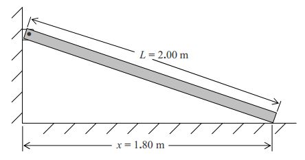
One end of a beam of mass 6.92 kg and of length 2.00 m is pin-connected to a wall. The other end of the beam rests on a frictionless floor at a point that is 1.80 m away from the wall. The beam is in a plane that is perpendicular to both the wall and the floor. The pin is perpendicular to that plane. Find the force exerted by the pin on the beam, and find the normal force exerted on the beam by the floor. Solution
First let’s draw a sketch:
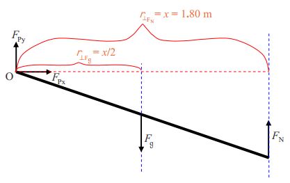
Now we draw a free body diagram of the member:

We are going to need to apply the torque equilibrium condition to the beam so I am going to add moment arms to the diagram. My plan is to sum the torques about point O so I will depict moment arms with respect to an axis through point O.
Now let’s apply the equilibrium conditions:
\[\sum F_{\rightarrow}=0 \nonumber \]
\[F_{Px}=0 \nonumber \]
There are three unknown force values depicted in the free body diagram and we have already found one of them! Let’s apply another equilibrium condition:
\[F_{\uparrow}=0 \nonumber \]
\[F_{Py}-F_g+F_N=0 \nonumber \]
\[F_{Py}-mg+F_N=0 \label{23-6} \]
There are two unknowns in this equation. We cannot solve it but it may prove useful later on. Let’s apply the torque equilibrium condition.
\[\sum \tau_{\circ \circlearrowleft}=0 \nonumber \]
\[-\dfrac{x}{2} F_g+xF_N=0 \nonumber \]
\[-\dfrac{x}{2}mg+xF_N=0 \nonumber \]
Here, I copy that last line for you before proceeding:
\[-\dfrac{x}{2}mg+xF_N=0 \nonumber \]
\[F_N=\dfrac{mg}{2} \nonumber \]
\[F_N=\dfrac{6.92kg(9.80 N/kg)}{2} \nonumber \]
\[F_N=32.9N \nonumber \]
We can use this result \((F_N=\frac{mg}{2})\) in Equation \(\ref{23-6}\) to obtain a value for \(F_Py\):
\[F_{Py}-mg+F_N=0 \nonumber \]
\[F_{Py}=mg-F_N \nonumber \]
\[F_{Py}=mg-\dfrac{mg}{2} \nonumber \]
\[F_{Py}=\dfrac{mg}{2} \nonumber \]
\[F_{Py}=\frac{6.92kg(9.80N/kg)}{2} \nonumber \]
\[F_{Py}=32.9N \nonumber \]
Recalling that we found \(F_{Px}\) to be zero, we can write, for our final answer:
\[\vec{F_p}=32.9 \quad \mbox{newtons, straight upward and} \nonumber \]
\[\vec{F_N}\quad \mbox{newtons, straight upward} \nonumber \]
Fix-Connected Members
A fix-connected member is one that is rigidly attached to a structure (such as a wall) that is external to the object whose equilibrium is under study. An example would be a metal rod, one end of which is welded to a metal wall. A fixed connection can apply a force in any direction, and it can apply a torque in any direction. When all the other forces lie in a plane, the force applied by the fixed connection will be in that plane. When all the other torques are along or parallel to a particular line, then the torque exerted by the fixed connection will be along or parallel to that same line.
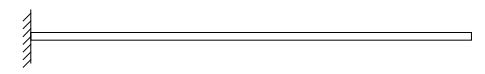
A horizontal bar of length L and mass \(m\) is fix connected to a wall. Find the force and the torque exerted on the bar by the wall. Solution
First a sketch:
then a free body diagram:
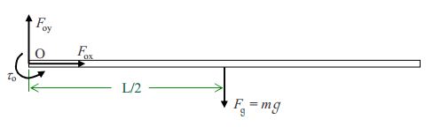
followed by the application of the equilibrium conditions to the free body diagram:
\[\sum F_{\rightarrow}=0 \nonumber \]
\[F_{ox}=0 \nonumber \]
That was quick. Let’s see what setting the sum of the vertical forces equal to zero yields:
\[\sum F_{\uparrow}=0 \nonumber \]
\[F_{oy}-F_g=0 \nonumber \]
\[F_{oy}=F_g \nonumber \]
\[F_{oy}=mg \nonumber \]
Now for the torque equilibrium condition:
\[\sum \tau_{\circ \circlearrowleft}=0 \nonumber \]
\[\tau_{\circ}-\frac{L}{2}F_g=0 \nonumber \]
\[\tau_{\circ}-\frac{L}{2} mg=0 \nonumber \]
\[\tau_{\circ}=\frac{1}{2}mgL \nonumber \]
The wall exerts an upward force of magnitude \(mg\), and a counterclockwise (as viewed from that position for which the free end of the bar is to the right) torque of magnitude \(\frac{1}{2}mgL\) on the bar.