
14.2: Mutual Inductance


- Last updated
- Mar 3, 2025
- Save as PDF

( \newcommand{\kernel}{\mathrm{null}\,}\)
By the end of this section, you will be able to:
- Correlate two nearby circuits that carry time-varying currents with the emf induced in each circuit
- Describe examples in which mutual inductance may or may not be desirable
Inductance is the property of a device that tells us how effectively it induces an emf in another device. In other words, it is a physical quantity that expresses the effectiveness of a given device.
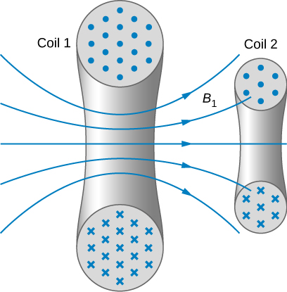
When two circuits carrying time-varying currents are close to one another, the magnetic flux through each circuit varies because of the changing current I in the other circuit. Consequently, an emf is induced in each circuit by the changing current in the other. This type of emf is therefore called a mutually induced emf, and the phenomenon that occurs is known as mutual inductance (M). As an example, let’s consider two tightly wound coils (Figure 14.2.1). Coils 1 and 2 have N1 and N2 turns and carry currents I1 and I2 respectively. The flux through a single turn of coil 2 produced by the magnetic field of the current in coil 1 is Φ12, whereas the flux through a single turn of coil 1 due to the magnetic field of I2 is Φ12.
The mutual inductance M21 of coil 2 with respect to coil 1 is the ratio of the flux through the N2 turns of coil 2 produced by the magnetic field of the current in coil 1, divided by that current, that is,
M21=N2Φ21I1.
Similarly, the mutual inductance of coil 1 with respect to coil 2 is
M12=N1Φ12I2.
Like capacitance, mutual inductance is a geometric quantity. It depends on the shapes and relative positions of the two coils, and it is independent of the currents in the coils. The SI unit for mutual inductance M is called the henry (H) in honor of Joseph Henry (1799–1878), an American scientist who discovered induced emf independently of Faraday. Thus, we have 1H=1V⋅s/A. From Equations ??? and ???, we can show that M21=M12, so we usually drop the subscripts associated with mutual inductance and write
M=N2Φ21I1=N1Φ12I2.
The emf developed in either coil is found by combining Faraday’s law and the definition of mutual inductance. Since N2Φ21 is the total flux through coil 2 due to I1, we obtain
ϵ2=−ddt(N2Φ21)=−ddt(MI1)=−MdI1dt
where we have used the fact that M is a time-independent constant because the geometry is time-independent. Similarly, we have
ϵ1=−MdI2dt.
In Equation ???, we can see the significance of the earlier description of mutual inductance (M) as a geometric quantity. The value of M neatly encapsulates the physical properties of circuit elements and allows us to separate the physical layout of the circuit from the dynamic quantities, such as the emf and the current. Equation ??? defines the mutual inductance in terms of properties in the circuit, whereas the previous definition of mutual inductance in Equation ??? is defined in terms of the magnetic flux experienced, regardless of circuit elements. You should be careful when using Equations 14.2.6 and 14.2.6 because ϵ1 and ϵ2 do not necessarily represent the total emfs in the respective coils. Each coil can also have an emf induced in it because of its self-inductance (self-inductance will be discussed in more detail in a later section).
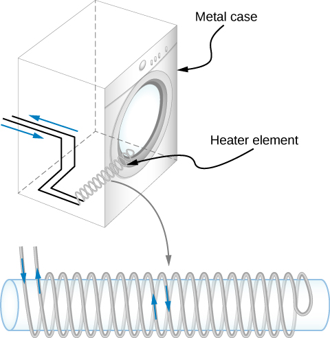
A large mutual inductance M may or may not be desirable. We want a transformer to have a large mutual inductance. But an appliance, such as an electric clothes dryer, can induce a dangerous emf on its metal case if the mutual inductance between its coils and the case is large. One way to reduce mutual inductance is to counter-wind coils to cancel the magnetic field produced (Figure 14.2.2).
Digital signal processing is another example in which mutual inductance is reduced by counter-winding coils. The rapid on/off emf representing 1s and 0s in a digital circuit creates a complex time-dependent magnetic field. An emf can be generated in neighboring conductors. If that conductor is also carrying a digital signal, the induced emf may be large enough to switch 1s and 0s, with consequences ranging from inconvenient to disastrous.
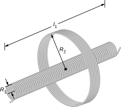
Figure 14.2.3 shows a coil of N2 turns and radius R2 surrounding a long solenoid of length l1, radius R1, and N1 turns.
- What is the mutual inductance of the two coils?
- If N1=500turns,N2=10turns,R1=3.10cm,l1=75.0cm, and the current in the solenoid is changing at a rate of 200 A/s, what is the emf induced in the surrounding coil?
Strategy
There is no magnetic field outside the solenoid, and the field inside has magnitude B1=μ0(N1/l1)I1 and is directed parallel to the solenoid’s axis. We can use this magnetic field to find the magnetic flux through the surrounding coil and then use this flux to calculate the mutual inductance for part (a), using Equation ???. We solve part (b) by calculating the mutual inductance from the given quantities and using Equation 14.2.6 to calculate the induced emf.
Solution
- The magnetic flux Φ21 through the surrounding coil is Φ21=B1πR21=μ0N1I1l1πR21. Now from Equation ???, the mutual inductance is M=N2Φ21I1=(N2I1)(μ0N1I1l1)πR21=μ0N1N2πR21l1.
- Using the previous expression and the given values, the mutual inductance is M=(4π×10−7T⋅m/A)(500)(10)π(0.0310m)20.750m=2.53×10−5H. Thus, from Equation 14.2.6, the emf induced in the surrounding coil is ϵ2=−MdI1dt=−(2.53×10⁻⁵H)(200A/s)=−5.06×10−3V.
Significance
Notice that M in part (a) is independent of the radius R2 of the surrounding coil because the solenoid’s magnetic field is confined to its interior. In principle, we can also calculate M by finding the magnetic flux through the solenoid produced by the current in the surrounding coil. This approach is much more difficult because Φ12 is so complicated. However, since M12=M21, we do know the result of this calculation.
A current I(t)=(5.0A)sin((120πrad/s)t) flows through the solenoid of part (b) of Example 14.2.1. What is the maximum emf induced in the surrounding coil?
Solution
4.77×10⁻²V