Physics LibreTexts

15.4: Comparing Simple Harmonic Motion and Circular Motion

  • Page ID
    4064
  • \( \newcommand{\vecs}[1]{\overset { \scriptstyle \rightharpoonup} {\mathbf{#1}} } \)

    \( \newcommand{\vecd}[1]{\overset{-\!-\!\rightharpoonup}{\vphantom{a}\smash {#1}}} \)

    \( \newcommand{\id}{\mathrm{id}}\) \( \newcommand{\Span}{\mathrm{span}}\)

    ( \newcommand{\kernel}{\mathrm{null}\,}\) \( \newcommand{\range}{\mathrm{range}\,}\)

    \( \newcommand{\RealPart}{\mathrm{Re}}\) \( \newcommand{\ImaginaryPart}{\mathrm{Im}}\)

    \( \newcommand{\Argument}{\mathrm{Arg}}\) \( \newcommand{\norm}[1]{\| #1 \|}\)

    \( \newcommand{\inner}[2]{\langle #1, #2 \rangle}\)

    \( \newcommand{\Span}{\mathrm{span}}\)

    \( \newcommand{\id}{\mathrm{id}}\)

    \( \newcommand{\Span}{\mathrm{span}}\)

    \( \newcommand{\kernel}{\mathrm{null}\,}\)

    \( \newcommand{\range}{\mathrm{range}\,}\)

    \( \newcommand{\RealPart}{\mathrm{Re}}\)

    \( \newcommand{\ImaginaryPart}{\mathrm{Im}}\)

    \( \newcommand{\Argument}{\mathrm{Arg}}\)

    \( \newcommand{\norm}[1]{\| #1 \|}\)

    \( \newcommand{\inner}[2]{\langle #1, #2 \rangle}\)

    \( \newcommand{\Span}{\mathrm{span}}\) \( \newcommand{\AA}{\unicode[.8,0]{x212B}}\)

    \( \newcommand{\vectorA}[1]{\vec{#1}}      % arrow\)

    \( \newcommand{\vectorAt}[1]{\vec{\text{#1}}}      % arrow\)

    \( \newcommand{\vectorB}[1]{\overset { \scriptstyle \rightharpoonup} {\mathbf{#1}} } \)

    \( \newcommand{\vectorC}[1]{\textbf{#1}} \)

    \( \newcommand{\vectorD}[1]{\overrightarrow{#1}} \)

    \( \newcommand{\vectorDt}[1]{\overrightarrow{\text{#1}}} \)

    \( \newcommand{\vectE}[1]{\overset{-\!-\!\rightharpoonup}{\vphantom{a}\smash{\mathbf {#1}}}} \)

    \( \newcommand{\vecs}[1]{\overset { \scriptstyle \rightharpoonup} {\mathbf{#1}} } \)

    \( \newcommand{\vecd}[1]{\overset{-\!-\!\rightharpoonup}{\vphantom{a}\smash {#1}}} \)

    \(\newcommand{\avec}{\mathbf a}\) \(\newcommand{\bvec}{\mathbf b}\) \(\newcommand{\cvec}{\mathbf c}\) \(\newcommand{\dvec}{\mathbf d}\) \(\newcommand{\dtil}{\widetilde{\mathbf d}}\) \(\newcommand{\evec}{\mathbf e}\) \(\newcommand{\fvec}{\mathbf f}\) \(\newcommand{\nvec}{\mathbf n}\) \(\newcommand{\pvec}{\mathbf p}\) \(\newcommand{\qvec}{\mathbf q}\) \(\newcommand{\svec}{\mathbf s}\) \(\newcommand{\tvec}{\mathbf t}\) \(\newcommand{\uvec}{\mathbf u}\) \(\newcommand{\vvec}{\mathbf v}\) \(\newcommand{\wvec}{\mathbf w}\) \(\newcommand{\xvec}{\mathbf x}\) \(\newcommand{\yvec}{\mathbf y}\) \(\newcommand{\zvec}{\mathbf z}\) \(\newcommand{\rvec}{\mathbf r}\) \(\newcommand{\mvec}{\mathbf m}\) \(\newcommand{\zerovec}{\mathbf 0}\) \(\newcommand{\onevec}{\mathbf 1}\) \(\newcommand{\real}{\mathbb R}\) \(\newcommand{\twovec}[2]{\left[\begin{array}{r}#1 \\ #2 \end{array}\right]}\) \(\newcommand{\ctwovec}[2]{\left[\begin{array}{c}#1 \\ #2 \end{array}\right]}\) \(\newcommand{\threevec}[3]{\left[\begin{array}{r}#1 \\ #2 \\ #3 \end{array}\right]}\) \(\newcommand{\cthreevec}[3]{\left[\begin{array}{c}#1 \\ #2 \\ #3 \end{array}\right]}\) \(\newcommand{\fourvec}[4]{\left[\begin{array}{r}#1 \\ #2 \\ #3 \\ #4 \end{array}\right]}\) \(\newcommand{\cfourvec}[4]{\left[\begin{array}{c}#1 \\ #2 \\ #3 \\ #4 \end{array}\right]}\) \(\newcommand{\fivevec}[5]{\left[\begin{array}{r}#1 \\ #2 \\ #3 \\ #4 \\ #5 \\ \end{array}\right]}\) \(\newcommand{\cfivevec}[5]{\left[\begin{array}{c}#1 \\ #2 \\ #3 \\ #4 \\ #5 \\ \end{array}\right]}\) \(\newcommand{\mattwo}[4]{\left[\begin{array}{rr}#1 \amp #2 \\ #3 \amp #4 \\ \end{array}\right]}\) \(\newcommand{\laspan}[1]{\text{Span}\{#1\}}\) \(\newcommand{\bcal}{\cal B}\) \(\newcommand{\ccal}{\cal C}\) \(\newcommand{\scal}{\cal S}\) \(\newcommand{\wcal}{\cal W}\) \(\newcommand{\ecal}{\cal E}\) \(\newcommand{\coords}[2]{\left\{#1\right\}_{#2}}\) \(\newcommand{\gray}[1]{\color{gray}{#1}}\) \(\newcommand{\lgray}[1]{\color{lightgray}{#1}}\) \(\newcommand{\rank}{\operatorname{rank}}\) \(\newcommand{\row}{\text{Row}}\) \(\newcommand{\col}{\text{Col}}\) \(\renewcommand{\row}{\text{Row}}\) \(\newcommand{\nul}{\text{Nul}}\) \(\newcommand{\var}{\text{Var}}\) \(\newcommand{\corr}{\text{corr}}\) \(\newcommand{\len}[1]{\left|#1\right|}\) \(\newcommand{\bbar}{\overline{\bvec}}\) \(\newcommand{\bhat}{\widehat{\bvec}}\) \(\newcommand{\bperp}{\bvec^\perp}\) \(\newcommand{\xhat}{\widehat{\xvec}}\) \(\newcommand{\vhat}{\widehat{\vvec}}\) \(\newcommand{\uhat}{\widehat{\uvec}}\) \(\newcommand{\what}{\widehat{\wvec}}\) \(\newcommand{\Sighat}{\widehat{\Sigma}}\) \(\newcommand{\lt}{<}\) \(\newcommand{\gt}{>}\) \(\newcommand{\amp}{&}\) \(\definecolor{fillinmathshade}{gray}{0.9}\)
    Learning Objectives
    • Describe how the sine and cosine functions relate to the concepts of circular motion
    • Describe the connection between simple harmonic motion and circular motion

    An easy way to model Simple Harmonic Motion (SHM) is by considering uniform circular motion. Figure \(\PageIndex{1}\) shows one way of using this method. A peg (a cylinder of wood) is attached to a vertical disk, rotating with a constant angular frequency.
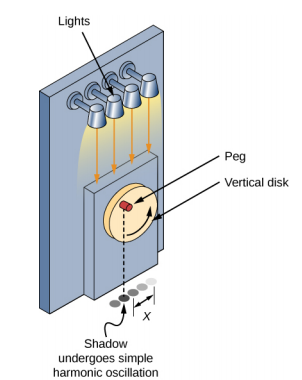
    An illustration of the method discussed in the text for casting an oscillating shadow. A peg protrudes from a vertical rotating disk that is mounted vertically on a wall. A set of lights shine down, illuminating the peg from above. The shadow of the peg is shown below as seen at several times during the oscillation, forming a series of points along a line parallel to the wall. The distance from the center of the line to the location of the shadow is x.
    Figure \(\PageIndex{1}\): SHM can be modeled as rotational motion by looking at the shadow of a peg on a wheel rotating at a constant angular frequency.

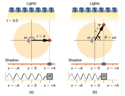
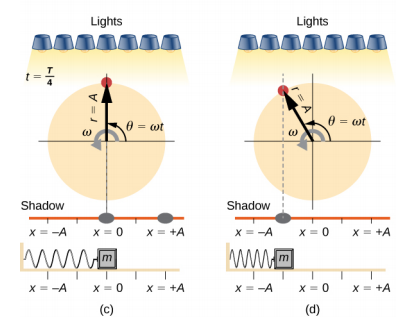
    Figure \(\PageIndex{2}\) shows a side view of the disk and peg. If a lamp is placed above the disk and peg, the peg produces a shadow. Let the disk have a radius of r = A and define the position of the shadow that coincides with the center line of the disk to be x = 0.00 m. As the disk rotates at a constant rate, the shadow oscillates between x = + A and x = −A. Now imagine a block on a spring beneath the floor as shown in Figure \(\PageIndex{2}\).

    A comparison of the angular location of a peg on a rotating disk, the position of its shadow, and the position of a mass oscillating on a horizontal spring. In each figure, the peg is illuminated from above by a set of lights, casting a shadow on a horizontal line. The disk has radius r = A and rotates counterclockwise with angular velocity omega. The angular position of the peg, theta, is zero when the peg is directly to the right of the center of the disk. The spring is attached to a wall on the left and a mass on the right. The position of the mass and the shadow is x, where x=0 is directly below the center of the disk , x=-A is directly below the left edge of the disk, and x=+A is directly below the right edge of the disk. In figure a, t=0.0. The peg is directly to the right of the center of the disk. Its shadow and the mass are both at x = +A. In figure b, the peg is at angle theta equals omega t, in the first quadrant. Its shadow and the mass are both directly below the peg at what appears to be x = +A/2. The time is not specified. In figure c, t=T/4. The peg is directly above the center of the disk. Its angular position theta equals omega t. Its shadow and the mass are both at x =0. In figure d, the peg is at angle theta equals omega t, now in the second quadrant. Its shadow and the mass are both directly below the peg at what appears to be x = -A/2. The time is not specified.

    A comparison of the angular location of a peg on a rotating disk, the position of its shadow, and the position of a mass oscillating on a horizontal spring. In each figure, the peg is illuminated from above by a set of lights, casting a shadow on a horizontal line. The disk has radius r = A and rotates counterclockwise with angular velocity omega. The angular position of the peg, theta, is zero when the peg is directly to the right of the center of the disk. The spring is attached to a wall on the left and a mass on the right. The position of the mass and the shadow is x, where x=0 is directly below the center of the disk , x=-A is directly below the left edge of the disk, and x=+A is directly below the right edge of the disk. In figure a, t=0.0. The peg is directly to the right of the center of the disk. Its shadow and the mass are both at x = +A. In figure b, the peg is at angle theta equals omega t, in the first quadrant. Its shadow and the mass are both directly below the peg at what appears to be x = +A/2. The time is not specified. In figure c, t=T/4. The peg is directly above the center of the disk. Its angular position theta equals omega t. Its shadow and the mass are both at x =0. In figure d, the peg is at angle theta equals omega t, now in the second quadrant. Its shadow and the mass are both directly below the peg at what appears to be x = -A/2. The time is not specified.
    Figure \(\PageIndex{2}\): Light shines down on the disk so that the peg makes a shadow. If the disk rotates at just the right angular frequency, the shadow follows the motion of the block on a spring. If there is no energy dissipated due to nonconservative forces, the block and the shadow will oscillate back and forth in unison. In this figure, four snapshots are taken at four different times. (a) The wheel starts at \(\theta\) = 0° and the shadow of the peg is at x = + A, representing the mass at position x = + A. (b) As the disk rotates through an angle \(\theta\) = \(\omega\)t, the shadow of the peg is between x = + A and x = 0. (c) The disk continues to rotate until \(\theta\) = 90°, at which the shadow follows the mass to x = 0. (d) The disk continues to rotate, the shadow follows the position of the mass.

    If the disk turns at the proper angular frequency, the shadow follows along with the block. The position of the shadow can be modeled with the equation

    \[x(t) = A \cos (\omega t) \ldotp \label{15.14}\]

    Recall that the block attached to the spring does not move at a constant velocity. How often does the wheel have to turn to have the peg’s shadow always on the block? The disk must turn at a constant angular frequency equal to 2\(\pi\) times the frequency of oscillation (\(\omega\) = 2\(\pi\)f).

    Figure \(\PageIndex{3}\) shows the basic relationship between uniform circular motion and SHM. The peg lies at the tip of the radius, a distance A from the center of the disk. The x-axis is defined by a line drawn parallel to the ground, cutting the disk in half. The y-axis (not shown) is defined by a line perpendicular to the ground, cutting the disk into a left half and a right half. The center of the disk is the point (x = 0, y = 0). The projection of the position of the peg onto the fixed x-axis gives the position of the shadow, which undergoes SHM analogous to the system of the block and spring. At the time shown in the figure, the projection has position x and moves to the left with velocity \(v\). The tangential velocity of the peg around the circle equals \(\bar{v}_{max}\) of the block on the spring. The x-component of the velocity is equal to the velocity of the block on the spring.
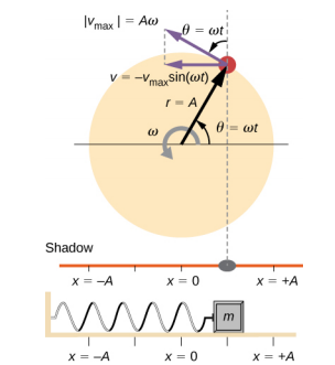
    A comparison of the angular location of a peg on a rotating disk, the position of its shadow, and the position of a mass oscillating on a horizontal spring. The disk has radius r = A and rotates counterclockwise with angular velocity omega. The angular position of the peg, theta, is zero when the peg is directly to the right of the center of the disk and is equal to omega t at the time shown. The linear velocity of the peg is shown as a vector tangent to the circle at the edge of the disk. It has magnitude v sub max which is equal to A omega. Its x component is a horizontal leftward vector – v sub max times sine omega t. The peg casts a shadow on a horizontal line. The spring is attached to a wall on the left and a mass on the right. The position of the mass and the shadow is x, where x=0 is directly below the center of the disk, x=-A is directly below the left edge of the disk, and x=+A is directly below the right edge of the disk. In the figure, the peg is in the first quadrant. Its shadow and the mass are both at a position x between 0 and plus A (it appears to be at x = A/2 in the figure.)
    Figure \(\PageIndex{3}\): - A peg moving on a circular path with a constant angular velocity ω is undergoing uniform circular motion. Its projection on the x-axis undergoes SHM. Also shown is the velocity of the peg around the circle, vmax, and its projection, which is v. Note that these velocities form a similar triangle to the displacement triangle.

    We can use Figure \(\PageIndex{3}\) to analyze the velocity of the shadow as the disk rotates. The peg moves in a circle with a speed of vmax = A\(\omega\). The shadow moves with a velocity equal to the component of the peg’s velocity that is parallel to the surface where the shadow is being produced:

    \[v = -v_{max} \sin (\omega t) \ldotp \label{15.15}\]

    It follows that the acceleration is

    \[a = -a_{max} \cos (\omega t) \ldotp \label{15.16}\]

    Exercise 15.3

    Identify an object that undergoes uniform circular motion. Describe how you could trace the SHM of this object.


    This page titled 15.4: Comparing Simple Harmonic Motion and Circular Motion is shared under a CC BY 4.0 license and was authored, remixed, and/or curated by OpenStax via source content that was edited to the style and standards of the LibreTexts platform.