1.3: The Law of Reflection
- Page ID
- 4486
\( \newcommand{\vecs}[1]{\overset { \scriptstyle \rightharpoonup} {\mathbf{#1}} } \)
\( \newcommand{\vecd}[1]{\overset{-\!-\!\rightharpoonup}{\vphantom{a}\smash {#1}}} \)
\( \newcommand{\id}{\mathrm{id}}\) \( \newcommand{\Span}{\mathrm{span}}\)
( \newcommand{\kernel}{\mathrm{null}\,}\) \( \newcommand{\range}{\mathrm{range}\,}\)
\( \newcommand{\RealPart}{\mathrm{Re}}\) \( \newcommand{\ImaginaryPart}{\mathrm{Im}}\)
\( \newcommand{\Argument}{\mathrm{Arg}}\) \( \newcommand{\norm}[1]{\| #1 \|}\)
\( \newcommand{\inner}[2]{\langle #1, #2 \rangle}\)
\( \newcommand{\Span}{\mathrm{span}}\)
\( \newcommand{\id}{\mathrm{id}}\)
\( \newcommand{\Span}{\mathrm{span}}\)
\( \newcommand{\kernel}{\mathrm{null}\,}\)
\( \newcommand{\range}{\mathrm{range}\,}\)
\( \newcommand{\RealPart}{\mathrm{Re}}\)
\( \newcommand{\ImaginaryPart}{\mathrm{Im}}\)
\( \newcommand{\Argument}{\mathrm{Arg}}\)
\( \newcommand{\norm}[1]{\| #1 \|}\)
\( \newcommand{\inner}[2]{\langle #1, #2 \rangle}\)
\( \newcommand{\Span}{\mathrm{span}}\) \( \newcommand{\AA}{\unicode[.8,0]{x212B}}\)
\( \newcommand{\vectorA}[1]{\vec{#1}} % arrow\)
\( \newcommand{\vectorAt}[1]{\vec{\text{#1}}} % arrow\)
\( \newcommand{\vectorB}[1]{\overset { \scriptstyle \rightharpoonup} {\mathbf{#1}} } \)
\( \newcommand{\vectorC}[1]{\textbf{#1}} \)
\( \newcommand{\vectorD}[1]{\overrightarrow{#1}} \)
\( \newcommand{\vectorDt}[1]{\overrightarrow{\text{#1}}} \)
\( \newcommand{\vectE}[1]{\overset{-\!-\!\rightharpoonup}{\vphantom{a}\smash{\mathbf {#1}}}} \)
\( \newcommand{\vecs}[1]{\overset { \scriptstyle \rightharpoonup} {\mathbf{#1}} } \)
\( \newcommand{\vecd}[1]{\overset{-\!-\!\rightharpoonup}{\vphantom{a}\smash {#1}}} \)
\(\newcommand{\avec}{\mathbf a}\) \(\newcommand{\bvec}{\mathbf b}\) \(\newcommand{\cvec}{\mathbf c}\) \(\newcommand{\dvec}{\mathbf d}\) \(\newcommand{\dtil}{\widetilde{\mathbf d}}\) \(\newcommand{\evec}{\mathbf e}\) \(\newcommand{\fvec}{\mathbf f}\) \(\newcommand{\nvec}{\mathbf n}\) \(\newcommand{\pvec}{\mathbf p}\) \(\newcommand{\qvec}{\mathbf q}\) \(\newcommand{\svec}{\mathbf s}\) \(\newcommand{\tvec}{\mathbf t}\) \(\newcommand{\uvec}{\mathbf u}\) \(\newcommand{\vvec}{\mathbf v}\) \(\newcommand{\wvec}{\mathbf w}\) \(\newcommand{\xvec}{\mathbf x}\) \(\newcommand{\yvec}{\mathbf y}\) \(\newcommand{\zvec}{\mathbf z}\) \(\newcommand{\rvec}{\mathbf r}\) \(\newcommand{\mvec}{\mathbf m}\) \(\newcommand{\zerovec}{\mathbf 0}\) \(\newcommand{\onevec}{\mathbf 1}\) \(\newcommand{\real}{\mathbb R}\) \(\newcommand{\twovec}[2]{\left[\begin{array}{r}#1 \\ #2 \end{array}\right]}\) \(\newcommand{\ctwovec}[2]{\left[\begin{array}{c}#1 \\ #2 \end{array}\right]}\) \(\newcommand{\threevec}[3]{\left[\begin{array}{r}#1 \\ #2 \\ #3 \end{array}\right]}\) \(\newcommand{\cthreevec}[3]{\left[\begin{array}{c}#1 \\ #2 \\ #3 \end{array}\right]}\) \(\newcommand{\fourvec}[4]{\left[\begin{array}{r}#1 \\ #2 \\ #3 \\ #4 \end{array}\right]}\) \(\newcommand{\cfourvec}[4]{\left[\begin{array}{c}#1 \\ #2 \\ #3 \\ #4 \end{array}\right]}\) \(\newcommand{\fivevec}[5]{\left[\begin{array}{r}#1 \\ #2 \\ #3 \\ #4 \\ #5 \\ \end{array}\right]}\) \(\newcommand{\cfivevec}[5]{\left[\begin{array}{c}#1 \\ #2 \\ #3 \\ #4 \\ #5 \\ \end{array}\right]}\) \(\newcommand{\mattwo}[4]{\left[\begin{array}{rr}#1 \amp #2 \\ #3 \amp #4 \\ \end{array}\right]}\) \(\newcommand{\laspan}[1]{\text{Span}\{#1\}}\) \(\newcommand{\bcal}{\cal B}\) \(\newcommand{\ccal}{\cal C}\) \(\newcommand{\scal}{\cal S}\) \(\newcommand{\wcal}{\cal W}\) \(\newcommand{\ecal}{\cal E}\) \(\newcommand{\coords}[2]{\left\{#1\right\}_{#2}}\) \(\newcommand{\gray}[1]{\color{gray}{#1}}\) \(\newcommand{\lgray}[1]{\color{lightgray}{#1}}\) \(\newcommand{\rank}{\operatorname{rank}}\) \(\newcommand{\row}{\text{Row}}\) \(\newcommand{\col}{\text{Col}}\) \(\renewcommand{\row}{\text{Row}}\) \(\newcommand{\nul}{\text{Nul}}\) \(\newcommand{\var}{\text{Var}}\) \(\newcommand{\corr}{\text{corr}}\) \(\newcommand{\len}[1]{\left|#1\right|}\) \(\newcommand{\bbar}{\overline{\bvec}}\) \(\newcommand{\bhat}{\widehat{\bvec}}\) \(\newcommand{\bperp}{\bvec^\perp}\) \(\newcommand{\xhat}{\widehat{\xvec}}\) \(\newcommand{\vhat}{\widehat{\vvec}}\) \(\newcommand{\uhat}{\widehat{\uvec}}\) \(\newcommand{\what}{\widehat{\wvec}}\) \(\newcommand{\Sighat}{\widehat{\Sigma}}\) \(\newcommand{\lt}{<}\) \(\newcommand{\gt}{>}\) \(\newcommand{\amp}{&}\) \(\definecolor{fillinmathshade}{gray}{0.9}\)By the end of this section, you will be able to:
- Explain the reflection of light from polished and rough surfaces
- Describe the principle and applications of corner reflectors
Whenever we look into a mirror, or squint at sunlight glinting from a lake, we are seeing a reflection. When you look at a piece of white paper, you are seeing light scattered from it. Large telescopes use reflection to form an image of stars and other astronomical objects.
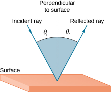
The law of reflection states that the angle of reflection equals the angle of incidence:
\[θ_r=θ_i \label{law of reflection} \]
The law of reflection is illustrated in Figure \(\PageIndex{1}\), which also shows how the angle of incidence and angle of reflection are measured relative to the perpendicular to the surface at the point where the light ray strikes.
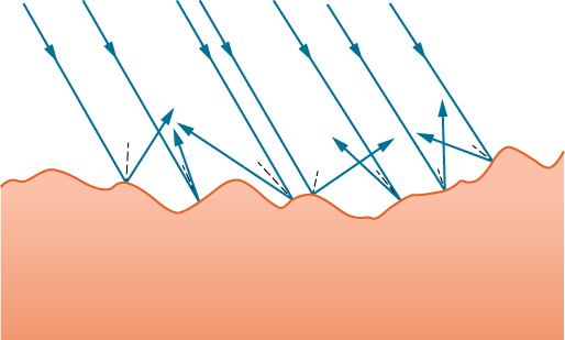
We expect to see reflections from smooth surfaces, but Figure \(\PageIndex{2}\) illustrates how a rough surface reflects light. Since the light strikes different parts of the surface at different angles, it is reflected in many different directions, or diffused. Diffused light is what allows us to see a sheet of paper from any angle, as shown in Figure \(\PageIndex{1a}\).
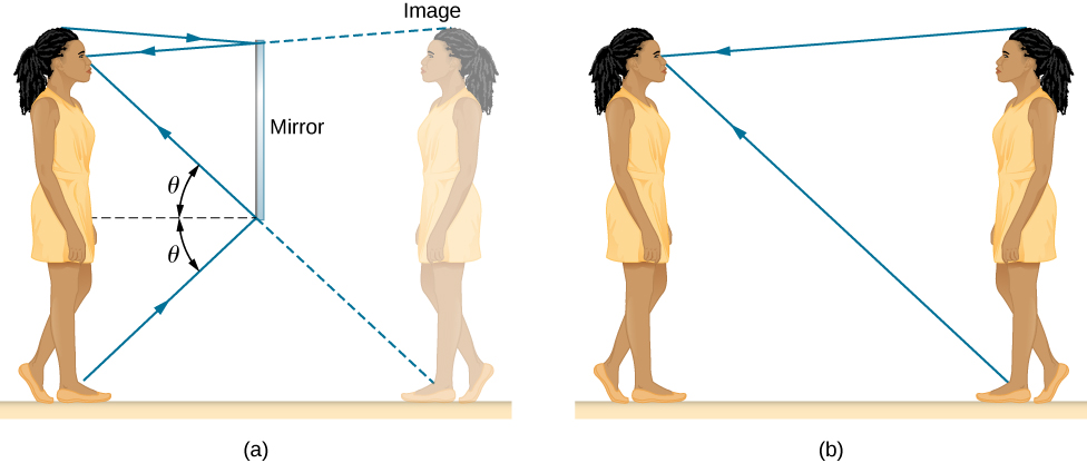
People, clothing, leaves, and walls all have rough surfaces and can be seen from all sides. A mirror, on the other hand, has a smooth surface (compared with the wavelength of light) and reflects light at specific angles, as illustrated in Figure \(\PageIndex{3b}\). When the Moon reflects from a lake, as shown in Figure \(\PageIndex{1c}\), a combination of these effects takes place.
When you see yourself in a mirror, it appears that the image is actually behind the mirror (Figure \(\PageIndex{4}\)). We see the light coming from a direction determined by the law of reflection. The angles are such that the image is exactly the same distance behind the mirror as you stand in front of the mirror. If the mirror is on the wall of a room, the images in it are all behind the mirror, which can make the room seem bigger. Although these mirror images make objects appear to be where they cannot be (like behind a solid wall), the images are not figments of your imagination. Mirror images can be photographed and videotaped by instruments and look just as they do with our eyes (which are optical instruments themselves). The precise manner in which images are formed by mirrors and lenses is discussed in an upcoming chapter on Geometric Optics and Image Formation.
Corner Reflectors (Retroreflectors)
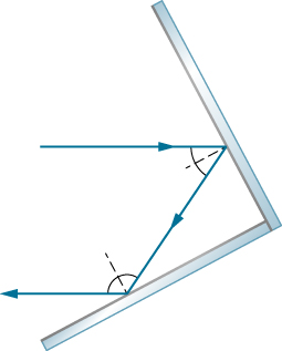
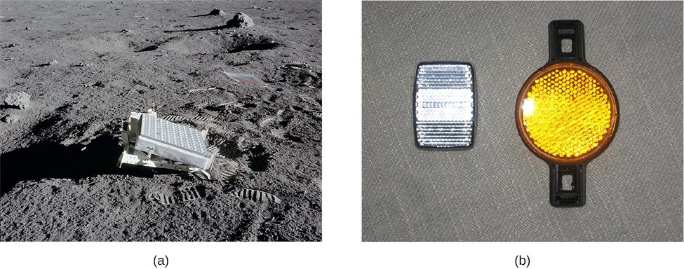
A light ray that strikes an object consisting of two mutually perpendicular reflecting surfaces is reflected back exactly parallel to the direction from which it came (Figure \(\PageIndex{5}\)). This is true whenever the reflecting surfaces are perpendicular, and it is independent of the angle of incidence. Such an object is called a corner reflector, since the light bounces from its inside corner. Corner reflectors are a subclass of retroreflectors, which all reflect rays back in the directions from which they came. Although the geometry of the proof is much more complex, corner reflectors can also be built with three mutually perpendicular reflecting surfaces and are useful in three-dimensional applications.
Many inexpensive reflector buttons on bicycles, cars, and warning signs have corner reflectors designed to return light in the direction from which it originated. Rather than simply reflecting light over a wide angle, retroreflection ensures high visibility if the observer and the light source are located together, such as a car’s driver and headlights. The Apollo astronauts placed a true corner reflector on the Moon (Figure \(\PageIndex{6}\)). Laser signals from Earth can be bounced from that corner reflector to measure the gradually increasing distance to the Moon of a few centimeters per year.
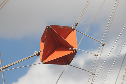
Working on the same principle as these optical reflectors, corner reflectors are routinely used as radar reflectors (Figure \(\PageIndex{7}\)) for radio-frequency applications. Under most circumstances, small boats made of fiberglass or wood do not strongly reflect radio waves emitted by radar systems. To make these boats visible to radar (to avoid collisions, for example), radar reflectors are attached to boats, usually in high places.
As a counterexample, if you are interested in building a stealth airplane, radar reflections should be minimized to evade detection. One of the design considerations would then be to avoid building 90°90° corners into the airframe.