
20.8: Sample problems and solutions
- Page ID
- 89783
\( \newcommand{\vecs}[1]{\overset { \scriptstyle \rightharpoonup} {\mathbf{#1}} } \)
\( \newcommand{\vecd}[1]{\overset{-\!-\!\rightharpoonup}{\vphantom{a}\smash {#1}}} \)
\( \newcommand{\dsum}{\displaystyle\sum\limits} \)
\( \newcommand{\dint}{\displaystyle\int\limits} \)
\( \newcommand{\dlim}{\displaystyle\lim\limits} \)
\( \newcommand{\id}{\mathrm{id}}\) \( \newcommand{\Span}{\mathrm{span}}\)
( \newcommand{\kernel}{\mathrm{null}\,}\) \( \newcommand{\range}{\mathrm{range}\,}\)
\( \newcommand{\RealPart}{\mathrm{Re}}\) \( \newcommand{\ImaginaryPart}{\mathrm{Im}}\)
\( \newcommand{\Argument}{\mathrm{Arg}}\) \( \newcommand{\norm}[1]{\| #1 \|}\)
\( \newcommand{\inner}[2]{\langle #1, #2 \rangle}\)
\( \newcommand{\Span}{\mathrm{span}}\)
\( \newcommand{\id}{\mathrm{id}}\)
\( \newcommand{\Span}{\mathrm{span}}\)
\( \newcommand{\kernel}{\mathrm{null}\,}\)
\( \newcommand{\range}{\mathrm{range}\,}\)
\( \newcommand{\RealPart}{\mathrm{Re}}\)
\( \newcommand{\ImaginaryPart}{\mathrm{Im}}\)
\( \newcommand{\Argument}{\mathrm{Arg}}\)
\( \newcommand{\norm}[1]{\| #1 \|}\)
\( \newcommand{\inner}[2]{\langle #1, #2 \rangle}\)
\( \newcommand{\Span}{\mathrm{span}}\) \( \newcommand{\AA}{\unicode[.8,0]{x212B}}\)
\( \newcommand{\vectorA}[1]{\vec{#1}} % arrow\)
\( \newcommand{\vectorAt}[1]{\vec{\text{#1}}} % arrow\)
\( \newcommand{\vectorB}[1]{\overset { \scriptstyle \rightharpoonup} {\mathbf{#1}} } \)
\( \newcommand{\vectorC}[1]{\textbf{#1}} \)
\( \newcommand{\vectorD}[1]{\overrightarrow{#1}} \)
\( \newcommand{\vectorDt}[1]{\overrightarrow{\text{#1}}} \)
\( \newcommand{\vectE}[1]{\overset{-\!-\!\rightharpoonup}{\vphantom{a}\smash{\mathbf {#1}}}} \)
\( \newcommand{\vecs}[1]{\overset { \scriptstyle \rightharpoonup} {\mathbf{#1}} } \)
\( \newcommand{\vecd}[1]{\overset{-\!-\!\rightharpoonup}{\vphantom{a}\smash {#1}}} \)
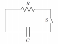
\(\newcommand{\avec}{\mathbf a}\) \(\newcommand{\bvec}{\mathbf b}\) \(\newcommand{\cvec}{\mathbf c}\) \(\newcommand{\dvec}{\mathbf d}\) \(\newcommand{\dtil}{\widetilde{\mathbf d}}\) \(\newcommand{\evec}{\mathbf e}\) \(\newcommand{\fvec}{\mathbf f}\) \(\newcommand{\nvec}{\mathbf n}\) \(\newcommand{\pvec}{\mathbf p}\) \(\newcommand{\qvec}{\mathbf q}\) \(\newcommand{\svec}{\mathbf s}\) \(\newcommand{\tvec}{\mathbf t}\) \(\newcommand{\uvec}{\mathbf u}\) \(\newcommand{\vvec}{\mathbf v}\) \(\newcommand{\wvec}{\mathbf w}\) \(\newcommand{\xvec}{\mathbf x}\) \(\newcommand{\yvec}{\mathbf y}\) \(\newcommand{\zvec}{\mathbf z}\) \(\newcommand{\rvec}{\mathbf r}\) \(\newcommand{\mvec}{\mathbf m}\) \(\newcommand{\zerovec}{\mathbf 0}\) \(\newcommand{\onevec}{\mathbf 1}\) \(\newcommand{\real}{\mathbb R}\) \(\newcommand{\twovec}[2]{\left[\begin{array}{r}#1 \\ #2 \end{array}\right]}\) \(\newcommand{\ctwovec}[2]{\left[\begin{array}{c}#1 \\ #2 \end{array}\right]}\) \(\newcommand{\threevec}[3]{\left[\begin{array}{r}#1 \\ #2 \\ #3 \end{array}\right]}\) \(\newcommand{\cthreevec}[3]{\left[\begin{array}{c}#1 \\ #2 \\ #3 \end{array}\right]}\) \(\newcommand{\fourvec}[4]{\left[\begin{array}{r}#1 \\ #2 \\ #3 \\ #4 \end{array}\right]}\) \(\newcommand{\cfourvec}[4]{\left[\begin{array}{c}#1 \\ #2 \\ #3 \\ #4 \end{array}\right]}\) \(\newcommand{\fivevec}[5]{\left[\begin{array}{r}#1 \\ #2 \\ #3 \\ #4 \\ #5 \\ \end{array}\right]}\) \(\newcommand{\cfivevec}[5]{\left[\begin{array}{c}#1 \\ #2 \\ #3 \\ #4 \\ #5 \\ \end{array}\right]}\) \(\newcommand{\mattwo}[4]{\left[\begin{array}{rr}#1 \amp #2 \\ #3 \amp #4 \\ \end{array}\right]}\) \(\newcommand{\laspan}[1]{\text{Span}\{#1\}}\) \(\newcommand{\bcal}{\cal B}\) \(\newcommand{\ccal}{\cal C}\) \(\newcommand{\scal}{\cal S}\) \(\newcommand{\wcal}{\cal W}\) \(\newcommand{\ecal}{\cal E}\) \(\newcommand{\coords}[2]{\left\{#1\right\}_{#2}}\) \(\newcommand{\gray}[1]{\color{gray}{#1}}\) \(\newcommand{\lgray}[1]{\color{lightgray}{#1}}\) \(\newcommand{\rank}{\operatorname{rank}}\) \(\newcommand{\row}{\text{Row}}\) \(\newcommand{\col}{\text{Col}}\) \(\renewcommand{\row}{\text{Row}}\) \(\newcommand{\nul}{\text{Nul}}\) \(\newcommand{\var}{\text{Var}}\) \(\newcommand{\corr}{\text{corr}}\) \(\newcommand{\len}[1]{\left|#1\right|}\) \(\newcommand{\bbar}{\overline{\bvec}}\) \(\newcommand{\bhat}{\widehat{\bvec}}\) \(\newcommand{\bperp}{\bvec^\perp}\) \(\newcommand{\xhat}{\widehat{\xvec}}\) \(\newcommand{\vhat}{\widehat{\vvec}}\) \(\newcommand{\uhat}{\widehat{\uvec}}\) \(\newcommand{\what}{\widehat{\wvec}}\) \(\newcommand{\Sighat}{\widehat{\Sigma}}\) \(\newcommand{\lt}{<}\) \(\newcommand{\gt}{>}\) \(\newcommand{\amp}{&}\) \(\definecolor{fillinmathshade}{gray}{0.9}\)A simple RC circuit as shown in Figure \(\PageIndex{1}\) contains a charged capacitor of unknown capacitance, \(C\), in series with a resistor, \(R=2\Omega\). When charged, the potential difference across the terminals of the capacitor is \(9\text{V}\).
At time \(t=0\text{s}\), the switch, \(S\), is closed, allowing the capacitor to discharge through the resistor. The current is then measured to be \(I = 0.05\text{A}\) at \(t = 5\text{s}\) after opening the switch.
- What is the capacitance of the capacitor?
- What charge did the capacitor hold at \(t = 2\text{s}\)?
- Answer
-
a. In this case, the capacitor is discharging as a function of time. At time \(t=0\), the voltage across the capacitor is \(\Delta V=9\text{V}\). We can model this discharging circuit in a similar way as we modeled the charging circuit.
We start with Kirchhoff’s junction rule, which leads to a differential equation for the charge stored on the capacitor, \(Q(t)\), as function of time:
\[\begin{aligned} \Delta V - IR &=0\\[4pt] \frac{Q}{C} - IR &=0\\[4pt] \frac{Q}{C} - \frac{dQ}{dt}R &=0\\[4pt] \therefore \frac{dQ}{dt} = -\frac{1}{RC}Q\end{aligned}\]
This differential equation is straightforward to solve, since it says that the derivative of \(Q(t)\) is equal to a constant multiplied by \(Q(t)\). Thus, \(Q(t)\), must be an exponential function:
\[\begin{aligned} Q(t) = Q_0 e^{-\frac{t}{RC}}\end{aligned}\]
where, \(Q_0\), is the (unknown) charge on the capacitor at \(t=0\). You can easily verify that taking the derivative of this equation will result in the differential equation being satisfied.
The current, \(I(t)\), as a function of time is given by:
\[\begin{aligned} I &=\frac{dQ}{dt}=-\frac{1}{RC}Q=\frac{Q_0}{RC} e^{-\frac{t}{RC}}=I_0e^{-\frac{t}{RC}}\end{aligned}\]
where \(I_0=\frac{Q_0}{RC}\) is the current at \(t=0\).
We also know that the current through the resistor at \(t=0\) is given by Ohm’s Law, since, at that time, the voltage, \(\frac{Q_0}{C}=9\text{V}\):
\[\begin{aligned} I_0=\frac{Q_0}{RC}=\frac{(9\text{V})}{(2\Omega)}=4.5\text{A}\end{aligned}\]
We then know that the current, at time \(t=5\text{s}\), is equal to \(I(5)=0.05\text{A}\), allowing us to determine the capacitance:
\[\begin{aligned} I(5)&=I_0e^{-\frac{t}{RC}}\\[4pt] \ln\left( \frac{I(5)}{I_0} \right)&=-\frac{t}{RC}\\[4pt] \therefore C&=\frac{t}{R \ln\left( \frac{I_0}{I(5)} \right)}=\frac{(5\text{s})}{(2\Omega)\ln\left( \frac{(4.5\text{A})}{(0.05\text{A})} \right)}=0.56\text{F}\end{aligned}\]
b. To find the charge stored in the capacitor at \(t = 2\text{s}\), we can use the function \(Q(t)\) that we determined before:
\[\begin{aligned} Q(t=2\text{s})=Q_0 e^{-\frac{t}{RC}}\end{aligned}\]
where we can determine, \(Q_0\), now that we know the capacitance. \(Q_0\) is the charge on the capacitor at time \(t=0\), when the voltage across the capacitor is \(9\text{V}\):
\[\begin{aligned} Q_0=C\Delta V = (0.56\text{F})(9\text{V})=5.0\text{C}\end{aligned}\]
At \(t = 2\text{s}\), the charge on the capacitor is thus:
\[\begin{aligned} Q(t = 2\text{s})=(5.0\text{C})e^{-\frac{(2\text{s})}{(2\Omega)(0.56\text{F})}}=0.84\text{C}\end{aligned}\]
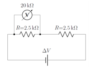
A voltmeter with a resistance of \(R_V = 20\text{k}\Omega\) is attached to a circuit with a battery of unknown voltage and two resistors with a resistance of \(R = 2.5\text{k}\Omega\) as shown in Figure \(\PageIndex{2}\). The voltmeter reads that the voltage drop over one of the resistors is \(\Delta V_{vm} =5.647\text{V}\). What is the voltage drop, \(V_R\), over each resistor when the voltmeter is removed from the circuit?
- Answer
-
In order to know the voltage across one of the resistors, we need to determine the voltage that is across the battery. Once we have determined the voltage across the battery, the voltage across one of the resistors will just be half of that across the battery, since the two resistors have the same resistance.
We can model the circuit with the voltmeter in place, since we know the voltage across the parallel combination of the voltmeter and resistor (that voltage which is readout by the voltmeter). We can combine the voltmeter and one of the resistors into a an equivalent resistor, \(R_{eff}\):
\[\begin{aligned} R_{eff} &= \frac{1}{R_V^{-1}+R^{-1}}\\[4pt] R_{eff} &= \frac{1}{(20\text{k}\Omega)^{-1}+(2.5\text{k}\Omega)^{-1}}\\[4pt] R_{eff} &= 2.22\text{k}\Omega\\[4pt]\end{aligned}\]
Now that we have the effective resistance as well as the voltage drop across that effective resistor, we can solve for current through the circuit:
\[\begin{aligned} I &= \frac{\Delta V_{vm}}{R_{eff}}\\[4pt] I &= \frac{5.647\text{V}}{2.22\text{k}\Omega}\\[4pt] I &= 2.541\text{mA}\\[4pt]\end{aligned}\]
Now that we have the current through the circuit, we can determine the voltage drop across the second resistor. By adding that voltage drop to the known voltage across the effective resistor, we can determine the battery voltage:
\[\begin{aligned} \Delta V_{battery} &= I(R_{eff}+R)\\[4pt] \Delta V_{battery} &= (2.541\text{mA})(2.222\text{k}\Omega+2.5\text{k}\Omega)\\[4pt] \Delta V_{battery} &= 12\text{V}\\[4pt]\end{aligned}\]
Thus, with no voltmeter present, the voltage across each resistor is \(6\text{V}\).