
20.E: Static Equilibrium and Elasticity (Exercises)


- Last updated
- Nov 4, 2023
- Save as PDF

( \newcommand{\kernel}{\mathrm{null}\,}\)
Conceptual Questions
- Under what conditions can a rotating body be in equilibrium? Give an example.
- What three factors affect the torque created by a force relative to a specific pivot point?
- Mechanics sometimes put a length of pipe over the handle of a wrench when trying to remove a very tight bolt. How does this help? For the next four problems, evaluate the statement as either true or false and explain your answer.
- If there is only one external force (or torque) acting on an object, it cannot be in equilibrium.
- If an object is in equilibrium there must be an even number of forces acting on it.
- If an odd number of forces act on an object, the object cannot be in equilibrium.
- A body moving in a circle with a constant speed is in rotational equilibrium.
- What purpose is served by a long and flexible pole carried by wire-walkers?
- Is it possible to rest a ladder against a rough wall when the floor is frictionless?
- Show how a spring scale and a simple fulcrum can be used to weigh an object whose weight is larger than the maximum reading on the scale.
- A painter climbs a ladder. Is the ladder more likely to slip when the painter is near the bottom or near the top?
Problems
- When tightening a bolt, you push perpendicularly on a wrench with a force of 165 N at a distance of 0.140 m from the center of the bolt. How much torque are you exerting relative to the center of the bolt?
- When opening a door, you push on it perpendicularly with a force of 55.0 N at a distance of 0.850 m from the hinges. What torque are you exerting relative to the hinges?
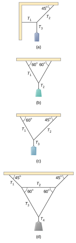
- Find the magnitude of the tension in each supporting cable shown below. In each case, the weight of the suspended body is 100.0 N and the masses of the cables are negligible.
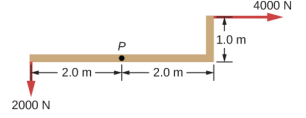
- What force must be applied at point P to keep the structure shown in equilibrium? The weight of the structure is negligible.
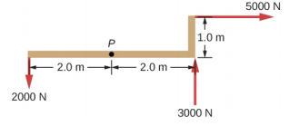
- Is it possible to apply a force at P to keep in equilibrium the structure shown? The weight of the structure is negligible.
- Two children push on opposite sides of a door during play. Both push horizontally and perpendicular to the door. One child pushes with a force of 17.5 N at a distance of 0.600 m from the hinges, and the second child pushes at a distance of 0.450 m. What force must the second child exert to keep the door from moving? Assume friction is negligible.
- A small 1000-kg SUV has a wheel base of 3.0 m. If 60% if its weight rests on the front wheels, how far behind the front wheels is the wagon’s center of mass?
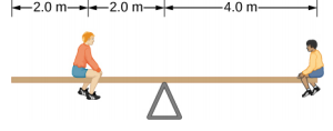
- The uniform seesaw is balanced at its center of mass, as seen below. The smaller boy on the right has a mass of 40.0 kg. What is the mass of his friend?
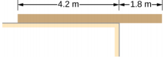
- A uniform plank rests on a level surface as shown below. The plank has a mass of 30 kg and is 6.0 m long. How much mass can be placed at its right end before it tips? (Hint: When the board is about to tip over, it makes contact with the surface only along the edge that becomes a momentary axis of rotation.)
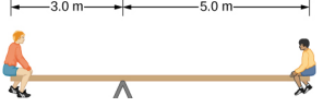
- The uniform seesaw shown below is balanced on a fulcrum located 3.0 m from the left end. The smaller boy on the right has a mass of 40 kg and the bigger boy on the left has a mass 80 kg. What is the mass of the board?
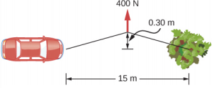
- In order to get his car out of the mud, a man ties one end of a rope to the front bumper and the other end to a tree 15 m away, as shown below. He then pulls on the center of the rope with a force of 400 N, which causes its center to be displaced 0.30 m, as shown. What is the force of the rope on the car?
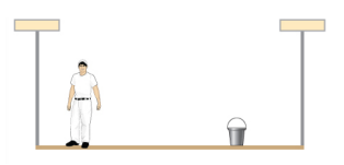
- A uniform 40.0-kg scaffold of length 6.0 m is supported by two light cables, as shown below. An 80.0-kg painter stands 1.0 m from the left end of the scaffold, and his painting equipment is 1.5 m from the right end. If the tension in the left cable is twice that in the right cable, find the tensions in the cables and the mass of the equipment.
- When the structure shown below is supported at point P, it is in equilibrium. Find the magnitude of force F and the force applied at P. The weight of the structure is negligible.

- To get up on the roof, a person (mass 70.0 kg) places a 6.00-m aluminum ladder (mass 10.0 kg) against the house on a concrete pad with the base of the ladder 2.00 m from the house. The ladder rests against a plastic rain gutter, which we can assume to be frictionless. The center of mass of the ladder is 2.00 m from the bottom. The person is standing 3.00 m from the bottom. Find the normal reaction and friction forces on the ladder at its base.
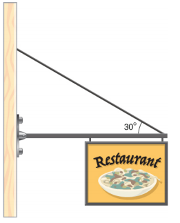
- A uniform horizontal strut weighs 400.0 N. One end of the strut is attached to a hinged support at the wall, and the other end of the strut is attached to a sign that weighs 200.0 N. The strut is also supported by a cable attached between the end of the strut and the wall. Assuming that the entire weight of the sign is attached at the very end of the strut, find the tension in the cable and the force at the hinge of the strut.
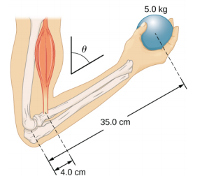
- The forearm shown below is positioned at an angle θ with respect to the upper arm, and a 5.0-kg mass is held in the hand. The total mass of the forearm and hand is 3.0 kg, and their center of mass is 15.0 cm from the elbow. (a) What is the magnitude of the force that the biceps muscle exerts on the forearm for θ = 60°? (b) What is the magnitude of the force on the elbow joint for the same angle? (c) How do these forces depend on the angle θ?
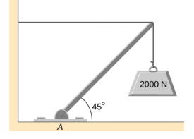
- The uniform boom shown below weighs 3000 N. It is supported by the horizontal guy wire and by the hinged support at point A. What are the forces on the boom due to the wire and due to the support at A? Does the force at A act along the boom?
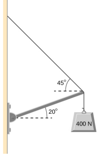
- The uniform boom shown below weighs 700 N, and the object hanging from its right end weighs 400 N. The boom is supported by a light cable and by a hinge at the wall. Calculate the tension in the cable and the force on the hinge on the boom. Does the force on the hinge act along the boom?
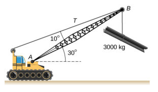
- A 12.0-m boom, AB, of a crane lifting a 3000-kg load is shown below. The center of mass of the boom is at its geometric center, and the mass of the boom is 1000 kg. For the position shown, calculate tension T in the cable and the force at the axle A.
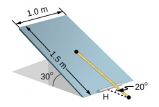
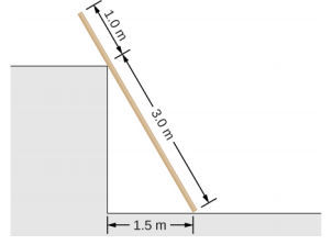
- A uniform trapdoor shown below is 1.0 m by 1.5 m and weighs 300 N. It is supported by a single hinge (H), and by a light rope tied between the middle of the door and the floor. The door is held at the position shown, where its slab makes a 30° angle with the horizontal floor and the rope makes a 20° angle with the floor. Find the tension in the rope and the force at the hinge.
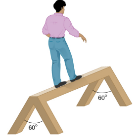
- A 90-kg man walks on a sawhorse, as shown below. The sawhorse is 2.0 m long and 1.0 m high, and its mass is 25.0 kg. Calculate the normal reaction force on each leg at the contact point with the floor when the man is 0.5 m from the far end of the sawhorse. (Hint: At each end, find the total reaction force first. This reaction force is the vector sum of two reaction forces, each acting along one leg. The normal reaction force at the contact point with the floor is the normal (with respect to the floor) component of this force.)
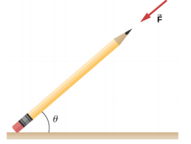
- The coefficient of static friction between the rubber eraser of the pencil and the tabletop is μs = 0.80. If the force →F is applied along the axis of the pencil, as shown below, what is the minimum angle at which the pencil can stand without slipping? Ignore the weight of the pencil.
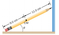
- A pencil rests against a corner, as shown below. The sharpened end of the pencil touches a smooth vertical surface and the eraser end touches a rough horizontal floor. The coefficient of static friction between the eraser and the floor is μs = 0.80. The center of mass of the pencil is located 9.0 cm from the tip of the eraser and 11.0 cm from the tip of the pencil lead. Find the minimum angle θ for which the pencil does not slip.
- A uniform 4.0-m plank weighing 200.0 N rests against the corner of a wall, as shown below. There is no friction at the point where the plank meets the corner. (a) Find the forces that the corner and the floor exert on the plank. (b) What is the minimum coefficient of static friction between the floor and the plank to prevent the plank from slipping?
- A 40-kg boy jumps from a height of 3.0 m, lands on one foot and comes to rest in 0.10 s after he hits the ground. Assume that he comes to rest with a constant deceleration. If the total cross-sectional area of the bones in his legs just above his ankles is 3.0 cm2, what is the compression stress in these bones? Leg bones can be fractured when they are subjected to stress greater than 1.7 x 10⁸ Pa. Is the boy in danger of breaking his leg?
- Two thin rods, one made of steel and the other of aluminum, are joined end to end. Each rod is 2.0 m long and has cross-sectional area 9.1 mm2. If a 10,000-N tensile force is applied at each end of the combination, find: (a) stress in each rod; (b) strain in each rod; and, (c) elongation of each rod.
- Two rods, one made of copper and the other of steel, have the same dimensions. If the copper rod stretches by 0.15 mm under some stress, how much does the steel rod stretch under the same stress?
Challenge Problems
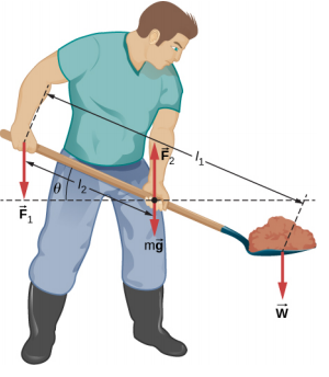
- In order to lift a shovelful of dirt, a gardener pushes downward on the end of the shovel and pulls upward at distance l2 from the end, as shown below. The weight of the shovel is m→g and acts at the point of application of →F2. Calculate the magnitudes of the forces →F1 and →F2 as functions of l1, l2, mg, and the weight W of the load. Why do your answers not depend on the angle theta that the shovel makes with the horizontal?
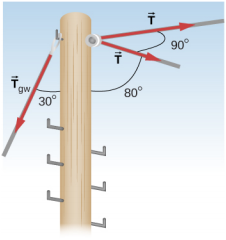
- The pole shown below is at a 90.0° bend in a power line and is therefore subjected to more shear force than poles in straight parts of the line. The tension in each line is 4.00 x 10⁴ N, at the angles shown. The pole is 15.0 m tall, has an 18.0 cm diameter, and can be considered to have half the strength of hardwood. (a) Calculate the compression of the pole. (b) Find how much it bends and in what direction. (c) Find the tension in a guy wire used to keep the pole straight if it is attached to the top of the pole at an angle of 30.0° with the vertical. The guy wire is in the opposite direction of the bend.
Contributors and Attributions
Samuel J. Ling (Truman State University), Jeff Sanny (Loyola Marymount University), and Bill Moebs with many contributing authors. This work is licensed by OpenStax University Physics under a Creative Commons Attribution License (by 4.0).