Conservation of Angular Momentum
- Last updated
- Jun 17, 2019
- Save as PDF
- Page ID
- 18012
( \newcommand{\kernel}{\mathrm{null}\,}\)
Learning Objectives
- Apply conservation of angular momentum to determine the angular velocity of a rotating system in which the moment of inertia is changing
- Explain how the rotational kinetic energy changes when a system undergoes changes in both moment of inertia and angular velocity
So far, we have looked at the angular momentum of systems consisting of point particles and rigid bodies. We have also analyzed the torques involved, using the expression that relates the external net torque to the change in angular momentum. Examples of systems that obey this equation include a freely spinning bicycle tire that slows over time due to torque arising from friction, or the slowing of Earth’s rotation over millions of years due to frictional forces exerted on tidal deformations.
However, suppose there is no net external torque on the system, ∑→τ = 0. In this case, we can introduce the law of conservation of angular momentum.
Law of Conservation of Angular Momentum
The angular momentum of a system of particles around a point in a fixed inertial reference frame is conserved if there is no net external torque around that point:
d→Ldt=0
or
→L=→l1+→l2+⋯+→lN=constant.
Note that the total angular momentum →L is conserved. Any of the individual angular momenta can change as long as their sum remains constant. This law is analogous to linear momentum being conserved when the external force on a system is zero.
As an example of conservation of angular momentum, Figure 1 shows an ice skater executing a spin. The net torque on her is very close to zero because there is relatively little friction between her skates and the ice. Also, the friction is exerted very close to the pivot point. Both |→F| and |→r| are small, so |→τ| is negligible. Consequently, she can spin for quite some time. She can also increase her rate of spin by pulling her arms and legs in. Why does pulling her arms and legs in increase her rate of spin? The answer is that her angular momentum is constant, so that
L′=L
or
I′ω′=Iω,
where the primed quantities refer to conditions after she has pulled in her arms and reduced her moment of inertia. Because I′ is smaller, the angular velocity ω′ must increase to keep the angular momentum constant.

It is interesting to see how the rotational kinetic energy of the skater changes when she pulls her arms in. Her initial rotational energy is
KRot=12Iω2,
whereas her final rotational energy is
K′Rot=12I(ω′)2.
Since I′ω′ = Iω, we can substitute for ω′ and find
K′Rot=12I′(ω′)2=12I′(II′ω)2=12Iω2(II′)=KRot(II′).
Because her moment of inertia has decreased, I′<I, her final rotational kinetic energy has increased. The source of this additional rotational kinetic energy is the work required to pull her arms inward. Note that the skater’s arms do not move in a perfect circle—they spiral inward. This work causes an increase in the rotational kinetic energy, while her angular momentum remains constant. Since she is in a frictionless environment, no energy escapes the system. Thus, if she were to extend her arms to their original positions, she would rotate at her original angular velocity and her kinetic energy would return to its original value.
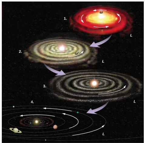
The solar system is another example of how conservation of angular momentum works in our universe. Our solar system was born from a huge cloud of gas and dust that initially had rotational energy. Gravitational forces caused the cloud to contract, and the rotation rate increased as a result of conservation of angular momentum (Figure 2).

We continue our discussion with an example that has applications to engineering.
Example 1: Coupled Flywheels
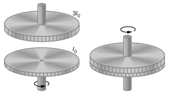
A flywheel rotates without friction at an angular velocity ω0 = 600 rev/min on a frictionless, vertical shaft of negligible rotational inertia. A second flywheel, which is at rest and has a moment of inertia three times that of the rotating flywheel, is dropped onto it (Figure 3). Because friction exists between the surfaces, the flywheels very quickly reach the same rotational velocity, after which they spin together.
- Use the law of conservation of angular momentum to determine the angular velocity ω of the combination.
- What fraction of the initial kinetic energy is lost in the coupling of the flywheels?

Strategy
Part (a) is straightforward to solve for the angular velocity of the coupled system. We use the result of (a) to compare the initial and final kinetic energies of the system in part (b).
Solution
- No external torques act on the system. The force due to friction produces an internal torque, which does not affect the angular momentum of the system. Therefore conservation of angular momentum gives I0ω0=(I0+3I0)ω, ω=14ω0=150rev/min=15.7rad/s.
- Before contact, only one flywheel is rotating. The rotational kinetic energy of this flywheel is the initial rotational kinetic energy of the system, 12I0ω20. The final kinetic energy is 12(4I0)ω2=12(4I0)(ω04)2=18I0ω20. Therefore, the ratio of the final kinetic energy to the initial kinetic energy is 18I0ω2012I0ω20=14. Thus, 3/4 of the initial kinetic energy is lost to the coupling of the two flywheels.
Significance
Since the rotational inertia of the system increased, the angular velocity decreased, as expected from the law of conservation of angular momentum. In this example, we see that the final kinetic energy of the system has decreased, as energy is lost to the coupling of the flywheels. Compare this to the example of the skater in Figure 1 doing work to bring her arms inward and adding rotational kinetic energy.
Exercise 1
A merry-go-round at a playground is rotating at 4.0 rev/min. Three children jump on and increase the moment of inertia of the merry-go-round/children rotating system by 25%. What is the new rotation rate?
Example 2A: Dismount from a High Bar
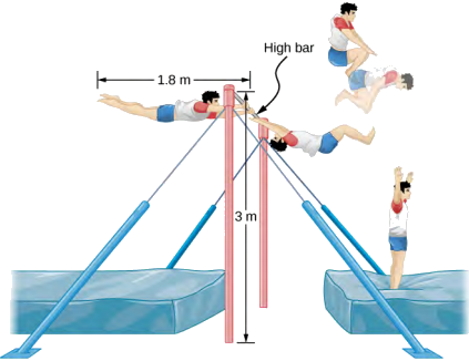
An 80.0-kg gymnast dismounts from a high bar. He starts the dismount at full extension, then tucks to complete a number of revolutions before landing. His moment of inertia when fully extended can be approximated as a rod of length 1.8 m and when in the tuck a rod of half that length. If his rotation rate at full extension is 1.0 rev/s and he enters the tuck when his center of mass is at 3.0 m height moving horizontally to the floor, how many revolutions can he execute if he comes out of the tuck at 1.8 m height? See Figure 4.

Strategy
Using conservation of angular momentum, we can find his rotation rate when in the tuck. Using the equations of kinematics, we can find the time interval from a height of 3.0 m to 1.8 m. Since he is moving horizontally with respect to the ground, the equations of free fall simplify. This will allow the number of revolutions that can be executed to be calculated. Since we are using a ratio, we can keep the units as rev/s and don’t need to convert to radians/s.
Solution
The moment of inertia at full extension is I0=112mL2=112(80.0kg)(1.8m)2=21.6kg⋅m2.
The moment of inertia in the tuck is If=112mL2f=112(80.0kg)(0.9m)2=5.4kg⋅m2.
Conservation of angular momentum: Ifωf=I0ω0⇒ωf=I0ω0If=(21.6kg⋅m2)(1.0rev/s)5.4kg⋅m2=4.0rev/s.
Time interval in the tuck: t=√2hg=√2(3.0−1.8)m9.8m/s=0.5s.
In 0.5 s, he will be able to execute two revolutions at 4.0 rev/s.
Significance
Note that the number of revolutions he can complete will depend on how long he is in the air. In the problem, he is exiting the high bar horizontally to the ground. He could also exit at an angle with respect to the ground, giving him more or less time in the air depending on the angle, positive or negative, with respect to the ground. Gymnasts must take this into account when they are executing their dismounts.
Example 2B: Conservation of Angular Momentum of a Collision
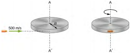
A bullet of mass m = 2.0 g is moving horizontally with a speed of 500.0 m/s. The bullet strikes and becomes embedded in the edge of a solid disk of mass M = 3.2 kg and radius R = 0.5 m. The cylinder is free to rotate around its axis and is initially at rest (Figure 5). What is the angular velocity of the disk immediately after the bullet is embedded?

Strategy
For the system of the bullet and the cylinder, no external torque acts along the vertical axis through the center of the disk. Thus, the angular momentum along this axis is conserved. The initial angular momentum of the bullet is mvR, which is taken about the rotational axis of the disk the moment before the collision. The initial angular momentum of the cylinder is zero. Thus, the net angular momentum of the system is mvR. Since angular momentum is conserved, the initial angular momentum of the system is equal to the angular momentum of the bullet embedded in the disk immediately after impact.
Solution
The initial angular momentum of the system is
Li=mvR.
The moment of inertia of the system with the bullet embedded in the disk is
I=mR2+12MR2=(m+M2)R2.
The final angular momentum of the system is
Lf=Iωf.
Thus, by conservation of angular momentum, Li = Lf and
mvR=(m+M2)R2ωf.
Solving for ωf,
ωf=mvR(m+M2)R2=(2.0×10⁻³kg)(500.0m/s)(2.0×10−3kg+1.6kg)(0.50m)=1.2rad/s.
Significance
The system is composed of both a point particle and a rigid body. Care must be taken when formulating the angular momentum before and after the collision. Just before impact the angular momentum of the bullet is taken about the rotational axis of the disk.


