Physics LibreTexts

11.26: Vector Nature of Rotational Kinematics

  • Page ID
    18273
  • \( \newcommand{\vecs}[1]{\overset { \scriptstyle \rightharpoonup} {\mathbf{#1}} } \)

    \( \newcommand{\vecd}[1]{\overset{-\!-\!\rightharpoonup}{\vphantom{a}\smash {#1}}} \)

    \( \newcommand{\id}{\mathrm{id}}\) \( \newcommand{\Span}{\mathrm{span}}\)

    ( \newcommand{\kernel}{\mathrm{null}\,}\) \( \newcommand{\range}{\mathrm{range}\,}\)

    \( \newcommand{\RealPart}{\mathrm{Re}}\) \( \newcommand{\ImaginaryPart}{\mathrm{Im}}\)

    \( \newcommand{\Argument}{\mathrm{Arg}}\) \( \newcommand{\norm}[1]{\| #1 \|}\)

    \( \newcommand{\inner}[2]{\langle #1, #2 \rangle}\)

    \( \newcommand{\Span}{\mathrm{span}}\)

    \( \newcommand{\id}{\mathrm{id}}\)

    \( \newcommand{\Span}{\mathrm{span}}\)

    \( \newcommand{\kernel}{\mathrm{null}\,}\)

    \( \newcommand{\range}{\mathrm{range}\,}\)

    \( \newcommand{\RealPart}{\mathrm{Re}}\)

    \( \newcommand{\ImaginaryPart}{\mathrm{Im}}\)

    \( \newcommand{\Argument}{\mathrm{Arg}}\)

    \( \newcommand{\norm}[1]{\| #1 \|}\)

    \( \newcommand{\inner}[2]{\langle #1, #2 \rangle}\)

    \( \newcommand{\Span}{\mathrm{span}}\) \( \newcommand{\AA}{\unicode[.8,0]{x212B}}\)

    \( \newcommand{\vectorA}[1]{\vec{#1}}      % arrow\)

    \( \newcommand{\vectorAt}[1]{\vec{\text{#1}}}      % arrow\)

    \( \newcommand{\vectorB}[1]{\overset { \scriptstyle \rightharpoonup} {\mathbf{#1}} } \)

    \( \newcommand{\vectorC}[1]{\textbf{#1}} \)

    \( \newcommand{\vectorD}[1]{\overrightarrow{#1}} \)

    \( \newcommand{\vectorDt}[1]{\overrightarrow{\text{#1}}} \)

    \( \newcommand{\vectE}[1]{\overset{-\!-\!\rightharpoonup}{\vphantom{a}\smash{\mathbf {#1}}}} \)

    \( \newcommand{\vecs}[1]{\overset { \scriptstyle \rightharpoonup} {\mathbf{#1}} } \)

    \( \newcommand{\vecd}[1]{\overset{-\!-\!\rightharpoonup}{\vphantom{a}\smash {#1}}} \)

    \(\newcommand{\avec}{\mathbf a}\) \(\newcommand{\bvec}{\mathbf b}\) \(\newcommand{\cvec}{\mathbf c}\) \(\newcommand{\dvec}{\mathbf d}\) \(\newcommand{\dtil}{\widetilde{\mathbf d}}\) \(\newcommand{\evec}{\mathbf e}\) \(\newcommand{\fvec}{\mathbf f}\) \(\newcommand{\nvec}{\mathbf n}\) \(\newcommand{\pvec}{\mathbf p}\) \(\newcommand{\qvec}{\mathbf q}\) \(\newcommand{\svec}{\mathbf s}\) \(\newcommand{\tvec}{\mathbf t}\) \(\newcommand{\uvec}{\mathbf u}\) \(\newcommand{\vvec}{\mathbf v}\) \(\newcommand{\wvec}{\mathbf w}\) \(\newcommand{\xvec}{\mathbf x}\) \(\newcommand{\yvec}{\mathbf y}\) \(\newcommand{\zvec}{\mathbf z}\) \(\newcommand{\rvec}{\mathbf r}\) \(\newcommand{\mvec}{\mathbf m}\) \(\newcommand{\zerovec}{\mathbf 0}\) \(\newcommand{\onevec}{\mathbf 1}\) \(\newcommand{\real}{\mathbb R}\) \(\newcommand{\twovec}[2]{\left[\begin{array}{r}#1 \\ #2 \end{array}\right]}\) \(\newcommand{\ctwovec}[2]{\left[\begin{array}{c}#1 \\ #2 \end{array}\right]}\) \(\newcommand{\threevec}[3]{\left[\begin{array}{r}#1 \\ #2 \\ #3 \end{array}\right]}\) \(\newcommand{\cthreevec}[3]{\left[\begin{array}{c}#1 \\ #2 \\ #3 \end{array}\right]}\) \(\newcommand{\fourvec}[4]{\left[\begin{array}{r}#1 \\ #2 \\ #3 \\ #4 \end{array}\right]}\) \(\newcommand{\cfourvec}[4]{\left[\begin{array}{c}#1 \\ #2 \\ #3 \\ #4 \end{array}\right]}\) \(\newcommand{\fivevec}[5]{\left[\begin{array}{r}#1 \\ #2 \\ #3 \\ #4 \\ #5 \\ \end{array}\right]}\) \(\newcommand{\cfivevec}[5]{\left[\begin{array}{c}#1 \\ #2 \\ #3 \\ #4 \\ #5 \\ \end{array}\right]}\) \(\newcommand{\mattwo}[4]{\left[\begin{array}{rr}#1 \amp #2 \\ #3 \amp #4 \\ \end{array}\right]}\) \(\newcommand{\laspan}[1]{\text{Span}\{#1\}}\) \(\newcommand{\bcal}{\cal B}\) \(\newcommand{\ccal}{\cal C}\) \(\newcommand{\scal}{\cal S}\) \(\newcommand{\wcal}{\cal W}\) \(\newcommand{\ecal}{\cal E}\) \(\newcommand{\coords}[2]{\left\{#1\right\}_{#2}}\) \(\newcommand{\gray}[1]{\color{gray}{#1}}\) \(\newcommand{\lgray}[1]{\color{lightgray}{#1}}\) \(\newcommand{\rank}{\operatorname{rank}}\) \(\newcommand{\row}{\text{Row}}\) \(\newcommand{\col}{\text{Col}}\) \(\renewcommand{\row}{\text{Row}}\) \(\newcommand{\nul}{\text{Nul}}\) \(\newcommand{\var}{\text{Var}}\) \(\newcommand{\corr}{\text{corr}}\) \(\newcommand{\len}[1]{\left|#1\right|}\) \(\newcommand{\bbar}{\overline{\bvec}}\) \(\newcommand{\bhat}{\widehat{\bvec}}\) \(\newcommand{\bperp}{\bvec^\perp}\) \(\newcommand{\xhat}{\widehat{\xvec}}\) \(\newcommand{\vhat}{\widehat{\vvec}}\) \(\newcommand{\uhat}{\widehat{\uvec}}\) \(\newcommand{\what}{\widehat{\wvec}}\) \(\newcommand{\Sighat}{\widehat{\Sigma}}\) \(\newcommand{\lt}{<}\) \(\newcommand{\gt}{>}\) \(\newcommand{\amp}{&}\) \(\definecolor{fillinmathshade}{gray}{0.9}\)

    learning objectives

    • Identify the direction of a vector using the Right Hand Rule

    Angular momentum and angular velocity have both magnitude and direction and, therefore, are vector quantities. The direction of these quantities is inherently difficult to track—a point on a rotating wheel is constantly rotating and changing direction. The axis of rotation of a rotating wheel is the only place that has a fixed direction. The direction of angular momentum and velocity can be determined along this axis.

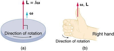
    Imagine the axis of rotation as a pole through the center of a wheel. The pole protrudes on both sides of the wheel and, depending on which side you’re looking at, the wheel is turning either clockwise or counterclockwise. This dependency on perspective makes determining the angle of rotation slightly more difficult. As with all physical quantities, there is a standard for measurement that makes these types of quantities consistent. For angular quantities, the direction of the vector is determined using the Right Hand Rule, illustrated in.

    image

    The Right Hand Rule: Figure (a) shows a disk is rotating counterclockwise when viewed from above. Figure (b) shows the right-hand rule. The direction of angular velocity ω size and angular momentum L are defined to be the direction in which the thumb of your right hand points when you curl your fingers in the direction of the disk’s rotation as shown.

    The right hand rule can be used to find the direction of both the angular momentum and the angular velocity. From a spinning disc, for example, let’s again imagine a pole through the center of the disc, at the axis of rotation. Using the right hand rule, your right hand would be grasping the pole so that your four fingers (index, middle, ring, and pinky) are following the direction of rotation. That is, an imaginary arrow from your wrist to your fingertips points in the same direction as the disc is rotating. In addition, your thumb is pointing straight out in the axis, perpendicular to your other fingers (or parallel to the ‘pole’ at the axis of rotation). Using this right hand rule, the direction of angular velocity ω and angular momentum L are defined as the direction in which the thumb of your right hand points when you curl your fingers in the direction of the disc’s rotation.

    Gyroscopes

    A gyroscope is a spinning wheel or disk in which the axle is free to assume any orientation.

    learning objectives

    • Compare the concept of a rotating wheel with a gyroscope

    A gyroscope is a device for measuring or maintaining orientation based on the principles of angular momentum. Mechanically, a gyroscope is a spinning wheel or disk in which the axle is free to assume any orientation. Although this orientation does not remain fixed, it changes in response to an external torque much less and in a different direction than it would without the large angular momentum associated with the disk’s high rate of spin and moment of inertia. The device’s orientation remains nearly fixed, regardless of the mounting platform’s motion, because mounting the device in a gimbal minimizes external torque.

    How It Works: Examples

    Torque: Torque changes angular momentum as expressed by the equation,

    \[\mathrm{τ=\dfrac{ΔL}{Δt}.}\]

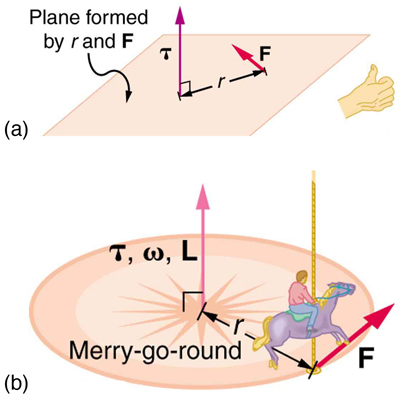
    This equation means that the direction of ΔL is the same as the direction of the torque that creates it, as illustrated in. This direction can be determined using the right hand rule, which says that the fingers on your hand curl towards the direction of rotation or force exerted, and your thumb points towards the direction of angular momentum, torque, and angular velocity.

    image

    Direction of Torque and Angular Momentum: In figure (a), the torque is perpendicular to the plane formed by r and F and is the direction your right thumb would point to if you curled your fingers in the direction of F. Figure (b) shows that the direction of the torque is the same as that of the angular momentum it produces.

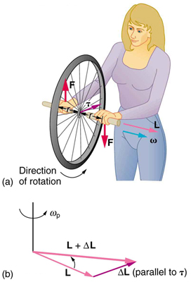
    Rotating wheel: Consider a bicycle wheel with handles attached to it, as in. With the wheel rotating as shown, its angular momentum is to the woman’s left. Suppose the person holding the wheel tries to rotate it as in the figure. Her natural expectation is that the wheel will rotate in the direction she pushes it, however, what happens is quite different. The forces exerted create a torque that is horizontal toward the person, and this torque creates a change in angular momentum L in the same direction, perpendicular to the original angular momentum L, thus changing the direction of L but not the magnitude of L. ΔL and L add, giving a new angular momentum with direction that is inclined more toward the person than before. The axis of the wheel has thus moved perpendicular to the forces exerted on it, instead of in the expected direction.

    image

    Gyroscopic Effect: In figure (a), a person holding the spinning bike wheel lifts it with her right hand and pushes down with her left hand in an attempt to rotate the wheel. This action creates a torque directly toward her. This torque causes a change in angular momentum ΔL in exactly the same direction. Figure (b) shows a vector diagram depicting how ΔL and L add, producing a new angular momentum pointing more toward the person. The wheel moves toward the person, perpendicular to the forces she exerts on it.

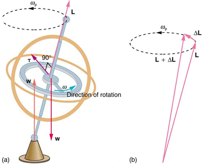
    Gyroscope: This same logic explains the behavior of gyroscopes (see ). There are two forces acting on a spinning gyroscope. The torque produced is perpendicular to the angular momentum, thus the direction of the angular momentum is changed, but not its magnitude. The gyroscope precesses around a vertical axis, since the torque is always horizontal and perpendicular to L. If the gyroscope is not spinning, it acquires angular momentum in the direction of the torque (L=ΔL), and it rotates around a horizontal axis, falling over just as we would expect.

    image

    Gyroscopes: As seen in figure (a), the forces on a spinning gyroscope are its weight and the supporting force from the stand. These forces create a horizontal torque on the gyroscope, which create a change in angular momentum ΔL that is also horizontal. In figure (b), ΔL and L add to produce a new angular momentum with the same magnitude, but different direction, so that the gyroscope precesses in the direction shown instead of falling over.

    Applications

    Gyroscopes serve as rotational sensors. For this reason, applications of gyroscopes include inertial navigation systems where magnetic compasses would not work (as in the Hubble telescope) or would not be precise enough (as in ICBMs). Another application is the stabilization of flying vehicles, such as radio-controlled helicopters or unmanned aerial vehicles.

    Key Points

    • Angular velocity and angular momentum are vector quantities and have both magnitude and direction.
    • The direction of angular velocity and angular momentum are perpendicular to the plane of rotation.
    • Using the right hand rule, the direction of both angular velocity and angular momentum is defined as the direction in which the thumb of your right hand points when you curl your fingers in the direction of rotation.
    • Torque is perpendicular to the plane formed by r and F and is the direction your right thumb would point if you curled the fingers of your right hand in the direction of F.
    • The direction of the torque is thus the same as that of the angular momentum it produces.
    • The gyroscope precesses around a vertical axis, since the torque is always horizontal and perpendicular to L. If the gyroscope is not spinning, it acquires angular momentum in the direction of the torque, and it rotates about a horizontal axis, falling over just as we would expect.

    Key Items

    • angular momentum: A vector quantity describing an object in circular motion; its magnitude is equal to the momentum of the particle, and the direction is perpendicular to the plane of its circular motion.
    • right hand rule: Direction of angular velocity ω and angular momentum L in which the thumb of your right hand points when you curl your fingers in the direction of rotation.
    • angular velocity: A vector quantity describing an object in circular motion; its magnitude is equal to the speed of the particle and the direction is perpendicular to the plane of its circular motion.
    • gimbal: A device for suspending something, such as a ship’s compass, so that it will remain level when its support is tipped.
    • torque: A rotational or twisting effect of a force; (SI unit newton-meter or Nm; imperial unit foot-pound or ft-lb)

    LICENSES AND ATTRIBUTIONS

    CC LICENSED CONTENT, SHARED PREVIOUSLY

    CC LICENSED CONTENT, SPECIFIC ATTRIBUTION


    11.26: Vector Nature of Rotational Kinematics is shared under a not declared license and was authored, remixed, and/or curated by LibreTexts.