
6.6: Application - Grounding and Electrical Safety


- Last updated
- Nov 17, 2024
- Save as PDF
( \newcommand{\kernel}{\mathrm{null}\,}\)
By the end of this section, you will be able to:
- Define thermal hazard, shock hazard, and short circuit.
- Explain what effects various levels of current have on the human body.
There are two known hazards of electricity—thermal and shock. A thermal hazard is one where excessive electric power causes undesired thermal effects, such as starting a fire in the wall of a house. A shock hazard occurs when electric current passes through a person. Shocks range in severity from painful, but otherwise harmless, to heart-stopping lethality. This section considers these hazards and the various factors affecting them in a quantitative manner. Electrical Safety: Systems and Devices will consider systems and devices for preventing electrical hazards.
Thermal Hazards
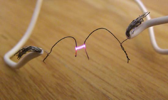
Electric power causes undesired heating effects whenever electric energy is converted to thermal energy at a rate faster than it can be safely dissipated. A classic example of this is the short circuit, a low-resistance path between terminals of a voltage source. An example of a short circuit is shown in Figure 1. Insulation on wires leading to an appliance has worn through, allowing the two wires to come into contact. Such an undesired contact with a high voltage is called a short. Since the resistance of the short, r, is very small, the power dissipated in the short, P=V2/r, is very large. for example, if V is 120 V and r is 0.100Ω, then the power is 144kW, much greater than that used by a typical household appliance. Thermal energy delivered at this rate will very quickly raise the temperature of surrounding materials, melting or perhaps igniting them.

One particularly insidious aspect of a short circuit is that its resistance may actually be decreased due to the increase in temperature. This can happen if the short creates ionization. These charged atoms and molecules are free to move and, thus, lower the resistance r. Since P=V2/r, the power dissipated in the short rises, possibly causing more ionization, more power, and so on. High voltages, such as the 480-V AC used in some industrial applications, lend themselves to this hazard, because higher voltages create higher initial power production in a short.
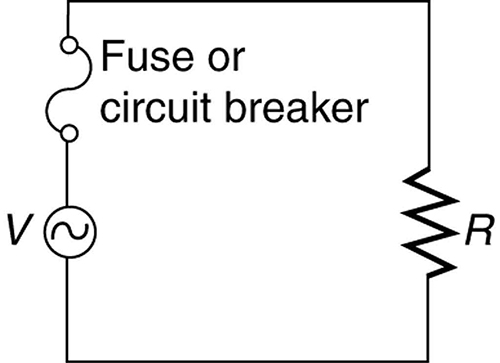
Another serious, but less dramatic, thermal hazard occurs when wires supplying power to a user are overloaded with too great a current. As discussed in the previous section, the power dissipated in the supply wires is P=I2RW, where RW is the resistance of the wires and I the current flowing through them. If either I or RW is too large, the wires overheat. For example, a worn appliance cord (with some of its braided wires broken) may have RW=2.00Ω rather than the 0.100Ω it should be. If 10.0 A of current passes through the cord, then P=I2RW=200W is dissipated in the cord—much more than is safe. Similarly, if a wire with a 0.100−Ω resistance is meant to carry a few amps, but is instead carrying 100 A, it will severely overheat. The power dissipated in the wire will in that case be P=1000W. Fuses and circuit breakers are used to limit excessive currents. (See Figure 2 and Figure 3.) Each device opens the circuit automatically when a sustained current exceeds safe limits.
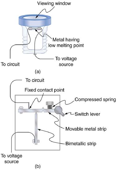
Fuses and circuit breakers for typical household voltages and currents are relatively simple to produce, but those for large voltages and currents experience special problems. For example, when a circuit breaker tries to interrupt the flow of high-voltage electricity, a spark can jump across its points that ionizes the air in the gap and allows the current to continue flowing. Large circuit breakers found in power-distribution systems employ insulating gas and even use jets of gas to blow out such sparks. Here AC is safer than DC, since AC current goes through zero 120 times per second, giving a quick opportunity to extinguish these arcs.
Shock Hazards
Electrical currents through people produce tremendously varied effects. An electrical current can be used to block back pain. The possibility of using electrical current to stimulate muscle action in paralyzed limbs, perhaps allowing paraplegics to walk, is under study. TV dramatizations in which electrical shocks are used to bring a heart attack victim out of ventricular fibrillation (a massively irregular, often fatal, beating of the heart) are more than common. Yet most electrical shock fatalities occur because a current put the heart into fibrillation. A pacemaker uses electrical shocks to stimulate the heart to beat properly. Some fatal shocks do not produce burns, but warts can be safely burned off with electric current (though freezing using liquid nitrogen is now more common). Of course, there are consistent explanations for these disparate effects. The major factors upon which the effects of electrical shock depend are
- The amount current I
- The path taken by the current
- The duration of the shock
- The frequency f of the current (f=0 for DC)
The table below gives the effects of electrical shocks as a function of current for a typical accidental shock. The effects are for a shock that passes through the trunk of the body, has a duration of 1 s, and is caused by 60-Hz power.
| Current (mA) | Effect |
| 1 | Threshold of sensation |
| 5 | Maximum harmless current |
| 10-20 | Onset of sustained muscular contraction; cannot let go for duration of shock; contraction of chest muscles may stop breathing during shock |
| 50 | Onset of pain |
| 100-300+ | Ventricular fibrillation possible; often fatal |
| 300 | Onset of burns depending on concentration of current |
| 6000 (6A) | Onset of sustained ventricular contraction and respiratory paralysis; both cease when shock ends; heartbeat may return to normal; used to defibrillate the heart |
Effects of Electrical Shock as a Function of Current
Our bodies are relatively good conductors due to the water in our bodies. Given that larger currents will flow through sections with lower resistance (to be further discussed in the next chapter), electric currents preferentially flow through paths in the human body that have a minimum resistance in a direct path to earth. The earth is a natural electron sink. Wearing insulating shoes, a requirement in many professions, prohibits a pathway for electrons by providing a large resistance in that path. Whenever working with high-power tools (drills), or in risky situations, ensure that you do not provide a pathway for current flow (especially through the heart).
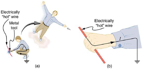
Very small currents pass harmlessly and unfelt through the body. This happens to you regularly without your knowledge. The threshold of sensation is only 1 mA and, although unpleasant, shocks are apparently harmless for currents less than 5 mA. A great number of safety rules take the 5-mA value for the maximum allowed shock. At 10 to 20 mA and above, the current can stimulate sustained muscular contractions much as regular nerve impulses do. People sometimes say they were knocked across the room by a shock, but what really happened was that certain muscles contracted, propelling them in a manner not of their own choosing. (See Figure 4a.) More frightening, and potentially more dangerous, is the “can’t let go” effect illustrated in Figure 4b.
The muscles that close the fingers are stronger than those that open them, so the hand closes involuntarily on the wire shocking it. This can prolong the shock indefinitely. It can also be a danger to a person trying to rescue the victim, because the rescuer’s hand may close about the victim’s wrist. Usually the best way to help the victim is to give the fist a hard knock/blow/jar with an insulator or to throw an insulator at the fist. Modern electric fences, used in animal enclosures, are now pulsed on and off to allow people who touch them to get free, rendering them less lethal than in the past.
Greater currents may affect the heart. Its electrical patterns can be disrupted, so that it beats irregularly and ineffectively in a condition called “ventricular fibrillation.” This condition often lingers after the shock and is fatal due to a lack of blood circulation. The threshold for ventricular fibrillation is between 100 and 300 mA. At about 300 mA and above, the shock can cause burns, depending on the concentration of current—the more concentrated, the greater the likelihood of burns.
Very large currents cause the heart and diaphragm to contract for the duration of the shock. Both the heart and breathing stop. Interestingly, both often return to normal following the shock. The electrical patterns on the heart are completely erased in a manner that the heart can start afresh with normal beating, as opposed to the permanent disruption caused by smaller currents that can put the heart into ventricular fibrillation. The latter is something like scribbling on a blackboard, whereas the former completely erases it. TV dramatizations of electric shock used to bring a heart attack victim out of ventricular fibrillation also show large paddles. These are used to spread out current passed through the victim to reduce the likelihood of burns.
Current is the major factor determining shock severity (given that other conditions such as path, duration, and frequency are fixed, such as in the table and preceding discussion). A larger voltage is more hazardous, but since I=V/R, the severity of the shock depends on the combination of voltage and resistance. For example, a person with dry skin has a resistance of about 200kΩ. If he comes into contact with 120-V AC, a current I=(120V)/(200kΩ)=.6mA passes harmlessly through him. The same person soaking wet may have a resistance of 10.0kΩ and the same 120 V will produce a current of 12 mA—above the “can’t let go” threshold and potentially dangerous.
Most of the body’s resistance is in its dry skin. When wet, salts go into ion form, lowering the resistance significantly. The interior of the body has a much lower resistance than dry skin because of all the ionic solutions and fluids it contains. If skin resistance is bypassed, such as by an intravenous infusion, a catheter, or exposed pacemaker leads, a person is rendered microshock sensitive. In this condition, currents about 1/1000 those listed in the table above produce similar effects. During open-heart surgery, currents as small as 20μA can be used to still the heart. Stringent electrical safety requirements in hospitals, particularly in surgery and intensive care, are related to the doubly disadvantaged microshock-sensitive patient. The break in the skin has reduced his resistance, and so the same voltage causes a greater current, and a much smaller current has a greater effect.
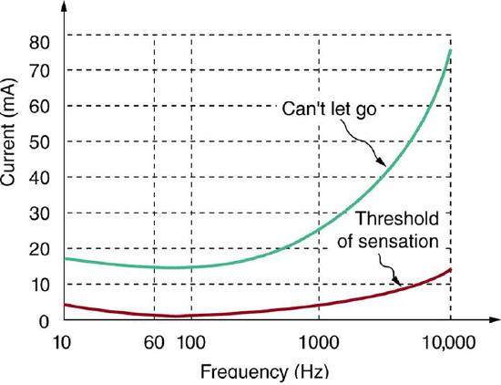
Factors other than current that affect the severity of a shock are its path, duration, and AC frequency. Path has obvious consequences. For example, the heart is unaffected by an electric shock through the brain, such as may be used to treat manic depression. And it is a general truth that the longer the duration of a shock, the greater its effects. Figure 5 presents a graph that illustrates the effects of frequency on a shock. The curves show the minimum current for two different effects, as a function of frequency. The lower the current needed, the more sensitive the body is at that frequency. Ironically, the body is most sensitive to frequencies near the 50- or 60-Hz frequencies in common use. The body is slightly less sensitive for DC (f=0), mildly confirming Edison’s claims that AC presents a greater hazard. At higher and higher frequencies, the body becomes progressively less sensitive to any effects that involve nerves. This is related to the maximum rates at which nerves can fire or be stimulated. At very high frequencies, electrical current travels only on the surface of a person. Thus a wart can be burned off with very high frequency current without causing the heart to stop. (Do not try this at home with 60-Hz AC!) Some of the spectacular demonstrations of electricity, in which high-voltage arcs are passed through the air and over people’s bodies, employ high frequencies and low currents. (See Figure 6.) Electrical safety safety devices and techniques are discussed in detail in Electrical Safety: Systems and Devices.
Electrical Safety: Systems and Devices
Figure 6.6.7(a) shows the schematic for a simple ac circuit with no safety features. This is not how power is distributed in practice. Modern household and industrial wiring requires the three-wire system, shown schematically in part (b), which has several safety features, with live, neutral, and ground wires. First is the familiar circuit breaker (or fuse) to prevent thermal overload. Second is a protective case around the appliance, such as a toaster or refrigerator. The case’s safety feature is that it prevents a person from touching exposed wires and coming into electrical contact with the circuit, helping prevent shocks.
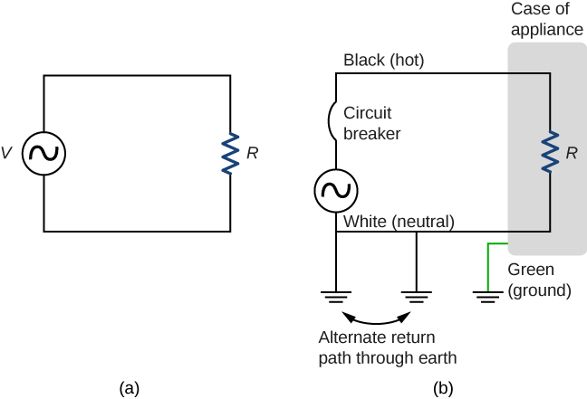
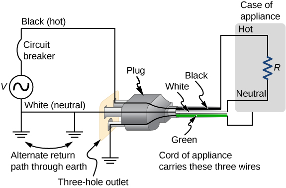
There are three connections to ground shown in 6.6.7(b). Recall that a ground connection is a low-resistance path directly to ground. The two ground connections on the neutral wire force it to be at zero volts relative to ground, giving the wire its name. This wire is therefore safe to touch even if its insulation, usually white, is missing. The neutral wire is the return path for the current to follow to complete the circuit. Furthermore, the two ground connections supply an alternative path through ground (a good conductor) to complete the circuit. The ground connection closest to the power source could be at the generating plant, whereas the other is at the user’s location. The third ground is to the case of the appliance, through the green ground wire, forcing the case, too, to be at zero volts. The live or hot wire (hereafter referred to as “live/hot”) supplies voltage and current to operate the appliance. Figure 6.6.8 shows a more pictorial version of how the three-wire system is connected through a three-prong plug to an appliance.
Insulating plastic is color-coded to identify live/hot, neutral, and ground wires, but these codes vary around the world. It is essential to determine the color code in your region. Striped coatings are sometimes used for the benefit of those who are colorblind.
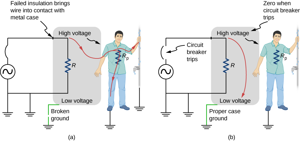
Grounding the case solves more than one problem. The simplest problem is worn insulation on the live/hot wire that allows it to contact the case, as shown in Figure (\PageIndex{9}\). Lacking a ground connection, a severe shock is possible. This is particularly dangerous in the kitchen, where a good connection to ground is available through water on the floor or a water faucet. With the ground connection intact, the circuit breaker will trip, forcing repair of the appliance.
A ground fault circuit interrupter (GFCI) is a safety device found in updated kitchen and bathroom wiring that works based on electromagnetic induction. GFCIs compare the currents in the live/hot and neutral wires. When live/hot and neutral currents are not equal, it is almost always because current in the neutral is less than in the live/hot wire. Then some of the current, called a leakage current, is returning to the voltage source by a path other than through the neutral wire. It is assumed that this path presents a hazard. GFCIs are usually set to interrupt the circuit if the leakage current is greater than 5 mA, the accepted maximum harmless shock. Even if the leakage current goes safely to ground through an intact ground wire, the GFCI will trip, forcing repair of the leakage.
Footnotes
1 For an average male shocked through trunk of body for 1 s by 60-Hz AC. Values for females are 60–80% of those listed.