Physics LibreTexts

3.7: Applications of Electrostatics

  • Page ID
    32168
  • \( \newcommand{\vecs}[1]{\overset { \scriptstyle \rightharpoonup} {\mathbf{#1}} } \)

    \( \newcommand{\vecd}[1]{\overset{-\!-\!\rightharpoonup}{\vphantom{a}\smash {#1}}} \)

    \( \newcommand{\id}{\mathrm{id}}\) \( \newcommand{\Span}{\mathrm{span}}\)

    ( \newcommand{\kernel}{\mathrm{null}\,}\) \( \newcommand{\range}{\mathrm{range}\,}\)

    \( \newcommand{\RealPart}{\mathrm{Re}}\) \( \newcommand{\ImaginaryPart}{\mathrm{Im}}\)

    \( \newcommand{\Argument}{\mathrm{Arg}}\) \( \newcommand{\norm}[1]{\| #1 \|}\)

    \( \newcommand{\inner}[2]{\langle #1, #2 \rangle}\)

    \( \newcommand{\Span}{\mathrm{span}}\)

    \( \newcommand{\id}{\mathrm{id}}\)

    \( \newcommand{\Span}{\mathrm{span}}\)

    \( \newcommand{\kernel}{\mathrm{null}\,}\)

    \( \newcommand{\range}{\mathrm{range}\,}\)

    \( \newcommand{\RealPart}{\mathrm{Re}}\)

    \( \newcommand{\ImaginaryPart}{\mathrm{Im}}\)

    \( \newcommand{\Argument}{\mathrm{Arg}}\)

    \( \newcommand{\norm}[1]{\| #1 \|}\)

    \( \newcommand{\inner}[2]{\langle #1, #2 \rangle}\)

    \( \newcommand{\Span}{\mathrm{span}}\) \( \newcommand{\AA}{\unicode[.8,0]{x212B}}\)

    \( \newcommand{\vectorA}[1]{\vec{#1}}      % arrow\)

    \( \newcommand{\vectorAt}[1]{\vec{\text{#1}}}      % arrow\)

    \( \newcommand{\vectorB}[1]{\overset { \scriptstyle \rightharpoonup} {\mathbf{#1}} } \)

    \( \newcommand{\vectorC}[1]{\textbf{#1}} \)

    \( \newcommand{\vectorD}[1]{\overrightarrow{#1}} \)

    \( \newcommand{\vectorDt}[1]{\overrightarrow{\text{#1}}} \)

    \( \newcommand{\vectE}[1]{\overset{-\!-\!\rightharpoonup}{\vphantom{a}\smash{\mathbf {#1}}}} \)

    \( \newcommand{\vecs}[1]{\overset { \scriptstyle \rightharpoonup} {\mathbf{#1}} } \)

    \( \newcommand{\vecd}[1]{\overset{-\!-\!\rightharpoonup}{\vphantom{a}\smash {#1}}} \)

    \(\newcommand{\avec}{\mathbf a}\) \(\newcommand{\bvec}{\mathbf b}\) \(\newcommand{\cvec}{\mathbf c}\) \(\newcommand{\dvec}{\mathbf d}\) \(\newcommand{\dtil}{\widetilde{\mathbf d}}\) \(\newcommand{\evec}{\mathbf e}\) \(\newcommand{\fvec}{\mathbf f}\) \(\newcommand{\nvec}{\mathbf n}\) \(\newcommand{\pvec}{\mathbf p}\) \(\newcommand{\qvec}{\mathbf q}\) \(\newcommand{\svec}{\mathbf s}\) \(\newcommand{\tvec}{\mathbf t}\) \(\newcommand{\uvec}{\mathbf u}\) \(\newcommand{\vvec}{\mathbf v}\) \(\newcommand{\wvec}{\mathbf w}\) \(\newcommand{\xvec}{\mathbf x}\) \(\newcommand{\yvec}{\mathbf y}\) \(\newcommand{\zvec}{\mathbf z}\) \(\newcommand{\rvec}{\mathbf r}\) \(\newcommand{\mvec}{\mathbf m}\) \(\newcommand{\zerovec}{\mathbf 0}\) \(\newcommand{\onevec}{\mathbf 1}\) \(\newcommand{\real}{\mathbb R}\) \(\newcommand{\twovec}[2]{\left[\begin{array}{r}#1 \\ #2 \end{array}\right]}\) \(\newcommand{\ctwovec}[2]{\left[\begin{array}{c}#1 \\ #2 \end{array}\right]}\) \(\newcommand{\threevec}[3]{\left[\begin{array}{r}#1 \\ #2 \\ #3 \end{array}\right]}\) \(\newcommand{\cthreevec}[3]{\left[\begin{array}{c}#1 \\ #2 \\ #3 \end{array}\right]}\) \(\newcommand{\fourvec}[4]{\left[\begin{array}{r}#1 \\ #2 \\ #3 \\ #4 \end{array}\right]}\) \(\newcommand{\cfourvec}[4]{\left[\begin{array}{c}#1 \\ #2 \\ #3 \\ #4 \end{array}\right]}\) \(\newcommand{\fivevec}[5]{\left[\begin{array}{r}#1 \\ #2 \\ #3 \\ #4 \\ #5 \\ \end{array}\right]}\) \(\newcommand{\cfivevec}[5]{\left[\begin{array}{c}#1 \\ #2 \\ #3 \\ #4 \\ #5 \\ \end{array}\right]}\) \(\newcommand{\mattwo}[4]{\left[\begin{array}{rr}#1 \amp #2 \\ #3 \amp #4 \\ \end{array}\right]}\) \(\newcommand{\laspan}[1]{\text{Span}\{#1\}}\) \(\newcommand{\bcal}{\cal B}\) \(\newcommand{\ccal}{\cal C}\) \(\newcommand{\scal}{\cal S}\) \(\newcommand{\wcal}{\cal W}\) \(\newcommand{\ecal}{\cal E}\) \(\newcommand{\coords}[2]{\left\{#1\right\}_{#2}}\) \(\newcommand{\gray}[1]{\color{gray}{#1}}\) \(\newcommand{\lgray}[1]{\color{lightgray}{#1}}\) \(\newcommand{\rank}{\operatorname{rank}}\) \(\newcommand{\row}{\text{Row}}\) \(\newcommand{\col}{\text{Col}}\) \(\renewcommand{\row}{\text{Row}}\) \(\newcommand{\nul}{\text{Nul}}\) \(\newcommand{\var}{\text{Var}}\) \(\newcommand{\corr}{\text{corr}}\) \(\newcommand{\len}[1]{\left|#1\right|}\) \(\newcommand{\bbar}{\overline{\bvec}}\) \(\newcommand{\bhat}{\widehat{\bvec}}\) \(\newcommand{\bperp}{\bvec^\perp}\) \(\newcommand{\xhat}{\widehat{\xvec}}\) \(\newcommand{\vhat}{\widehat{\vvec}}\) \(\newcommand{\uhat}{\widehat{\uvec}}\) \(\newcommand{\what}{\widehat{\wvec}}\) \(\newcommand{\Sighat}{\widehat{\Sigma}}\) \(\newcommand{\lt}{<}\) \(\newcommand{\gt}{>}\) \(\newcommand{\amp}{&}\) \(\definecolor{fillinmathshade}{gray}{0.9}\)
    Learning Objectives

    By the end of this section, you will be able to:

    • Describe some of the many practical applications of electrostatics, including several printing technologies
    • Relate these applications to Newton’s second law and the electric force

    The study of electrostatics has proven useful in many areas. This module covers just a few of the many applications of electrostatics.

    The Van de Graaff Generator

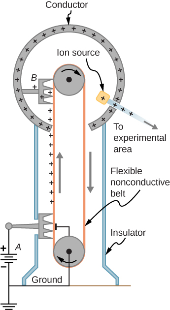
    Van de Graaff generators (or Van de Graaffs) are not only spectacular devices used to demonstrate high voltage due to static electricity—they are also used for serious research. The first was built by Robert Van de Graaff in 1931 (based on original suggestions by Lord Kelvin) for use in nuclear physics research. Figure \(\PageIndex{1}\) shows a schematic of a large research version. Van de Graaffs use both smooth and pointed surfaces, and conductors and insulators to generate large static charges and, hence, large voltages.

    A very large excess charge can be deposited on the sphere because it moves quickly to the outer surface. Practical limits arise because the large electric fields polarize and eventually ionize surrounding materials, creating free charges that neutralize excess charge or allow it to escape. Nevertheless, voltages of 15 million volts are well within practical limits.

    The figure shows the schematic of Van de Graaff generator.
    Figure \(\PageIndex{1}\): Schematic of Van de Graaff generator. A battery (A) supplies excess positive charge to a pointed conductor, the points of which spray the charge onto a moving insulating belt near the bottom. The pointed conductor (B) on top in the large sphere picks up the charge. (The induced electric field at the points is so large that it removes the charge from the belt.) This can be done because the charge does not remain inside the conducting sphere but moves to its outside surface. An ion source inside the sphere produces positive ions, which are accelerated away from the positive sphere to high velocities.

    Xerography

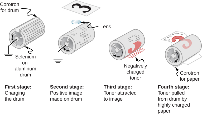
    Most copy machines use an electrostatic process called xerography—a word coined from the Greek words xeros for dry and graphos for writing. The heart of the process is shown in simplified form in Figure \(\PageIndex{2}\).

    The figure illustrates the four stages of Xerography – charging the drum, positive image made on drum, toner attached to image and toner pulled from drum by highly charged paper.
    Figure \(\PageIndex{2}\): Xerography is a dry copying process based on electrostatics. The major steps in the process are the charging of the photoconducting drum, transfer of an image, creating a positive charge duplicate, attraction of toner to the charged parts of the drum, and transfer of toner to the paper. Not shown are heat treatment of the paper and cleansing of the drum for the next copy.

    A selenium-coated aluminum drum is sprayed with positive charge from points on a device called a corotron. Selenium is a substance with an interesting property—it is a photoconductor. That is, selenium is an insulator when in the dark and a conductor when exposed to light.

    In the first stage of the xerography process, the conducting aluminum drum is grounded so that a negative charge is induced under the thin layer of uniformly positively charged selenium. In the second stage, the surface of the drum is exposed to the image of whatever is to be copied. In locations where the image is light, the selenium becomes conducting, and the positive charge is neutralized. In dark areas, the positive charge remains, so the image has been transferred to the drum.

    The third stage takes a dry black powder, called toner, and sprays it with a negative charge so that it is attracted to the positive regions of the drum. Next, a blank piece of paper is given a greater positive charge than on the drum so that it will pull the toner from the drum. Finally, the paper and electrostatically held toner are passed through heated pressure rollers, which melt and permanently adhere the toner to the fibers of the paper.

    Laser Printers

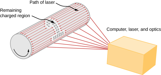
    Laser printers use the xerographic process to make high-quality images on paper, employing a laser to produce an image on the photoconducting drum as shown in Figure \(\PageIndex{3}\). In its most common application, the laser printer receives output from a computer, and it can achieve high-quality output because of the precision with which laser light can be controlled. Many laser printers do significant information processing, such as making sophisticated letters or fonts, and in the past may have contained a computer more powerful than the one giving them the raw data to be printed.

    The figure illustrates the laser printing process, showing the drum, path of laser, remaining charged region and computer, laser and optics.
    Figure \(\PageIndex{3}\): In a laser printer, a laser beam is scanned across a photoconducting drum, leaving a positively charged image. The other steps for charging the drum and transferring the image to paper are the same as in xerography. Laser light can be very precisely controlled, enabling laser printers to produce high-quality images.

    Ink Jet Printers and Electrostatic Painting

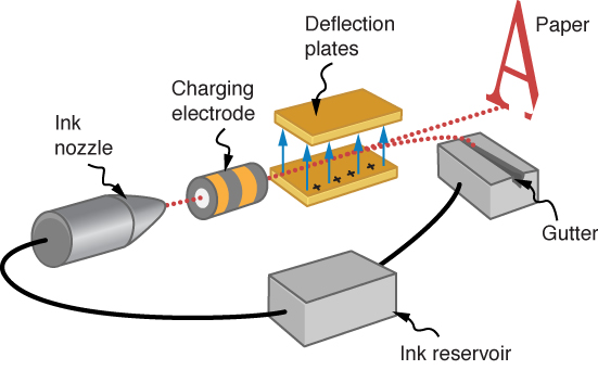
    The ink jet printer, commonly used to print computer-generated text and graphics, also employs electrostatics. A nozzle makes a fine spray of tiny ink droplets, which are then given an electrostatic charge (Figure \(\PageIndex{4}\)).

    Once charged, the droplets can be directed, using pairs of charged plates, with great precision to form letters and images on paper. Ink jet printers can produce color images by using a black jet and three other jets with primary colors, usually cyan, magenta, and yellow, much as a color television produces color. (This is more difficult with xerography, requiring multiple drums and toners.)

    The figure illustrates the ink jet printing process with the gutter, ink reservoir, ink nozzle, charging electrode, deflection plates and paper.
    Figure \(\PageIndex{4}\): The nozzle of an ink-jet printer produces small ink droplets, which are sprayed with electrostatic charge. Various computer-driven devices are then used to direct the droplets to the correct positions on a page.

    Electrostatic painting employs electrostatic charge to spray paint onto oddly shaped surfaces. Mutual repulsion of like charges causes the paint to fly away from its source. Surface tension forms drops, which are then attracted by unlike charges to the surface to be painted. Electrostatic painting can reach hard-to-get-to places, applying an even coat in a controlled manner. If the object is a conductor, the electric field is perpendicular to the surface, tending to bring the drops in perpendicularly. Corners and points on conductors will receive extra paint. Felt can similarly be applied.

    Smoke Precipitators and Electrostatic Air Cleaning

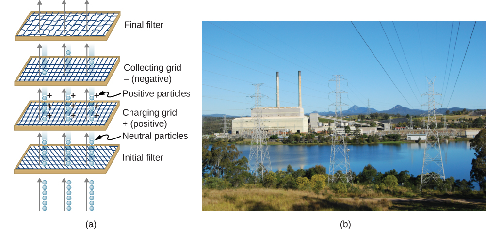
    Another important application of electrostatics is found in air cleaners, both large and small. The electrostatic part of the process places excess (usually positive) charge on smoke, dust, pollen, and other particles in the air and then passes the air through an oppositely charged grid that attracts and retains the charged particles (Figure \(\PageIndex{5}\))

    Large electrostatic precipitators are used industrially to remove over \(99\%\) of the particles from stack gas emissions associated with the burning of coal and oil. Home precipitators, often in conjunction with the home heating and air conditioning system, are very effective in removing polluting particles, irritants, and allergens.

    Part a shows the schematic of an electrostatic precipitator with four filters – initial filter, charging grid positive, charging grid negative and final filter. The photo in part b shows a power plant on a river to illustrate the effect of electrostatic precipitators.
    Figure \(\PageIndex{5}\): (a) Schematic of an electrostatic precipitator. Air is passed through grids of opposite charge. The first grid charges airborne particles, while the second attracts and collects them. (b) The dramatic effect of electrostatic precipitators is seen by the absence of smoke from this power plant. (credit b: modification of work by “Cmdalgleish”/Wikimedia Commons)

    Contributors and Attributions

    Samuel J. Ling (Truman State University), Jeff Sanny (Loyola Marymount University), and Bill Moebs with many contributing authors. This work is licensed by OpenStax University Physics under a Creative Commons Attribution License (by 4.0).


    This page titled 3.7: Applications of Electrostatics is shared under a CC BY license and was authored, remixed, and/or curated by OpenStax.