
9.A: Electromagnetic Induction (Answers)
- Page ID
- 32237

\( \newcommand{\vecs}[1]{\overset { \scriptstyle \rightharpoonup} {\mathbf{#1}} } \)
\( \newcommand{\vecd}[1]{\overset{-\!-\!\rightharpoonup}{\vphantom{a}\smash {#1}}} \)
\( \newcommand{\dsum}{\displaystyle\sum\limits} \)
\( \newcommand{\dint}{\displaystyle\int\limits} \)
\( \newcommand{\dlim}{\displaystyle\lim\limits} \)
\( \newcommand{\id}{\mathrm{id}}\) \( \newcommand{\Span}{\mathrm{span}}\)
( \newcommand{\kernel}{\mathrm{null}\,}\) \( \newcommand{\range}{\mathrm{range}\,}\)
\( \newcommand{\RealPart}{\mathrm{Re}}\) \( \newcommand{\ImaginaryPart}{\mathrm{Im}}\)
\( \newcommand{\Argument}{\mathrm{Arg}}\) \( \newcommand{\norm}[1]{\| #1 \|}\)
\( \newcommand{\inner}[2]{\langle #1, #2 \rangle}\)
\( \newcommand{\Span}{\mathrm{span}}\)
\( \newcommand{\id}{\mathrm{id}}\)
\( \newcommand{\Span}{\mathrm{span}}\)
\( \newcommand{\kernel}{\mathrm{null}\,}\)
\( \newcommand{\range}{\mathrm{range}\,}\)
\( \newcommand{\RealPart}{\mathrm{Re}}\)
\( \newcommand{\ImaginaryPart}{\mathrm{Im}}\)
\( \newcommand{\Argument}{\mathrm{Arg}}\)
\( \newcommand{\norm}[1]{\| #1 \|}\)
\( \newcommand{\inner}[2]{\langle #1, #2 \rangle}\)
\( \newcommand{\Span}{\mathrm{span}}\) \( \newcommand{\AA}{\unicode[.8,0]{x212B}}\)
\( \newcommand{\vectorA}[1]{\vec{#1}} % arrow\)
\( \newcommand{\vectorAt}[1]{\vec{\text{#1}}} % arrow\)
\( \newcommand{\vectorB}[1]{\overset { \scriptstyle \rightharpoonup} {\mathbf{#1}} } \)
\( \newcommand{\vectorC}[1]{\textbf{#1}} \)
\( \newcommand{\vectorD}[1]{\overrightarrow{#1}} \)
\( \newcommand{\vectorDt}[1]{\overrightarrow{\text{#1}}} \)
\( \newcommand{\vectE}[1]{\overset{-\!-\!\rightharpoonup}{\vphantom{a}\smash{\mathbf {#1}}}} \)
\( \newcommand{\vecs}[1]{\overset { \scriptstyle \rightharpoonup} {\mathbf{#1}} } \)
\(\newcommand{\longvect}{\overrightarrow}\)
\( \newcommand{\vecd}[1]{\overset{-\!-\!\rightharpoonup}{\vphantom{a}\smash {#1}}} \)
\(\newcommand{\avec}{\mathbf a}\) \(\newcommand{\bvec}{\mathbf b}\) \(\newcommand{\cvec}{\mathbf c}\) \(\newcommand{\dvec}{\mathbf d}\) \(\newcommand{\dtil}{\widetilde{\mathbf d}}\) \(\newcommand{\evec}{\mathbf e}\) \(\newcommand{\fvec}{\mathbf f}\) \(\newcommand{\nvec}{\mathbf n}\) \(\newcommand{\pvec}{\mathbf p}\) \(\newcommand{\qvec}{\mathbf q}\) \(\newcommand{\svec}{\mathbf s}\) \(\newcommand{\tvec}{\mathbf t}\) \(\newcommand{\uvec}{\mathbf u}\) \(\newcommand{\vvec}{\mathbf v}\) \(\newcommand{\wvec}{\mathbf w}\) \(\newcommand{\xvec}{\mathbf x}\) \(\newcommand{\yvec}{\mathbf y}\) \(\newcommand{\zvec}{\mathbf z}\) \(\newcommand{\rvec}{\mathbf r}\) \(\newcommand{\mvec}{\mathbf m}\) \(\newcommand{\zerovec}{\mathbf 0}\) \(\newcommand{\onevec}{\mathbf 1}\) \(\newcommand{\real}{\mathbb R}\) \(\newcommand{\twovec}[2]{\left[\begin{array}{r}#1 \\ #2 \end{array}\right]}\) \(\newcommand{\ctwovec}[2]{\left[\begin{array}{c}#1 \\ #2 \end{array}\right]}\) \(\newcommand{\threevec}[3]{\left[\begin{array}{r}#1 \\ #2 \\ #3 \end{array}\right]}\) \(\newcommand{\cthreevec}[3]{\left[\begin{array}{c}#1 \\ #2 \\ #3 \end{array}\right]}\) \(\newcommand{\fourvec}[4]{\left[\begin{array}{r}#1 \\ #2 \\ #3 \\ #4 \end{array}\right]}\) \(\newcommand{\cfourvec}[4]{\left[\begin{array}{c}#1 \\ #2 \\ #3 \\ #4 \end{array}\right]}\) \(\newcommand{\fivevec}[5]{\left[\begin{array}{r}#1 \\ #2 \\ #3 \\ #4 \\ #5 \\ \end{array}\right]}\) \(\newcommand{\cfivevec}[5]{\left[\begin{array}{c}#1 \\ #2 \\ #3 \\ #4 \\ #5 \\ \end{array}\right]}\) \(\newcommand{\mattwo}[4]{\left[\begin{array}{rr}#1 \amp #2 \\ #3 \amp #4 \\ \end{array}\right]}\) \(\newcommand{\laspan}[1]{\text{Span}\{#1\}}\) \(\newcommand{\bcal}{\cal B}\) \(\newcommand{\ccal}{\cal C}\) \(\newcommand{\scal}{\cal S}\) \(\newcommand{\wcal}{\cal W}\) \(\newcommand{\ecal}{\cal E}\) \(\newcommand{\coords}[2]{\left\{#1\right\}_{#2}}\) \(\newcommand{\gray}[1]{\color{gray}{#1}}\) \(\newcommand{\lgray}[1]{\color{lightgray}{#1}}\) \(\newcommand{\rank}{\operatorname{rank}}\) \(\newcommand{\row}{\text{Row}}\) \(\newcommand{\col}{\text{Col}}\) \(\renewcommand{\row}{\text{Row}}\) \(\newcommand{\nul}{\text{Nul}}\) \(\newcommand{\var}{\text{Var}}\) \(\newcommand{\corr}{\text{corr}}\) \(\newcommand{\len}[1]{\left|#1\right|}\) \(\newcommand{\bbar}{\overline{\bvec}}\) \(\newcommand{\bhat}{\widehat{\bvec}}\) \(\newcommand{\bperp}{\bvec^\perp}\) \(\newcommand{\xhat}{\widehat{\xvec}}\) \(\newcommand{\vhat}{\widehat{\vvec}}\) \(\newcommand{\uhat}{\widehat{\uvec}}\) \(\newcommand{\what}{\widehat{\wvec}}\) \(\newcommand{\Sighat}{\widehat{\Sigma}}\) \(\newcommand{\lt}{<}\) \(\newcommand{\gt}{>}\) \(\newcommand{\amp}{&}\) \(\definecolor{fillinmathshade}{gray}{0.9}\)Check Your Understanding
13.1. 1.1 T/s
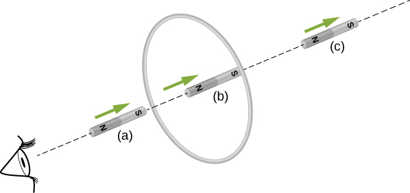
13.2. To the observer shown, the current flows clockwise as the magnet approaches, decreases to zero when the magnet is centered in the plane of the coil, and then flows counterclockwise as the magnet leaves the coil.
13.4. \(\displaystyle ε=Bl^2ω/2\), with O at a higher potential than S
13.5. 1.5 V
13.6. a. yes;
b. Yes; however there is a lack of symmetry between the electric field and coil, making \(\displaystyle ∮\vec{E}⋅d\vec{l}\) a more complicated relationship that can’t be simplified as shown in the example.
13.7. \(\displaystyle 3.4×10^{−3}V/m\)
13.8. \(\displaystyle P_1,P)2,P_4\)
13.9. a. \(\displaystyle 3.1×10^{−6}V;\)
b. \(\displaystyle 2.0×10^{−7}V/m\)
Conceptual Questions
1. The emf depends on the rate of change of the magnetic field.
3. Both have the same induced electric fields; however, the copper ring has a much higher induced emf because it conducts electricity better than the wooden ring.
5. a. no; b. yes
7. As long as the magnetic flux is changing from positive to negative or negative to positive, there could be an induced emf.
9. Position the loop so that the field lines run perpendicular to the area vector or parallel to the surface.
11. a. CW as viewed from the circuit; b. CCW as viewed from the circuit
13. As the loop enters, the induced emf creates a CCW current while as the loop leaves the induced emf creates a CW current. While the loop is fully inside the magnetic field, there is no flux change and therefore no induced current.
15. a. CCW viewed from the magnet;
b. CW viewed from the magnet;
c. CW viewed from the magnet;
d. CCW viewed from the magnet;
e. CW viewed from the magnet;
f. no current
17. Positive charges on the wings would be to the west, or to the left of the pilot while negative charges would be pulled east or to the right of the pilot. Thus, the left hand tips of the wings would be positive and the right hand tips would be negative.
19. The work is greater than the kinetic energy because it takes energy to counteract the induced emf.
21. The conducting sheet is shielded from the changing magnetic fields by creating an induced emf. This induced emf creates an induced magnetic field that opposes any changes in magnetic fields from the field underneath. Therefore, there is no net magnetic field in the region above this sheet. If the field were due to a static magnetic field, no induced emf will be created since you need a changing magnetic flux to induce an emf. Therefore, this static magnetic field will not be shielded.
23. a. zero induced current, zero force; b. clockwise induced current, force is to the left; c. zero induced current, zero force; d. counterclockwise induced current, force is to the left; e. zero induced current, zero force.
Problems
25. a. 3.8 V;
b. 2.2 V;
c. 0 V
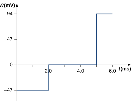
27. \(\displaystyle B=1.5t,0≤t<2.0ms,B=3.0mT,2.0ms≤t≤5.0ms,\)
\(\displaystyle B=−3.0t+18mT,5.0ms<t≤6.0ms,\)
\(\displaystyle ε=−\frac{dΦm}{dt}=−\frac{d(BA)}{dt}=−A\frac{dB}{dt},\)
\(\displaystyle ε=−π(0.100m)^2(1.5T/s)\)
\(\displaystyle =−47mV(0≤t<2.0ms),\)
\(\displaystyle ε=π(0.100m)^2(0)=0(2.0ms≤t≤5.0ms),\)
\(\displaystyle ε=−π(0.100m)^2(−3.0T/s)=94mV(5.0ms<t<6.0ms).\)
29. Each answer is 20 times the previously given answers.
31. \(\displaystyle \hat{n}=\hat{k},dΦ_m=Cysin(ωt)dxdy,\)
\(\displaystyle Φ_m=\frac{Cab^2sin(ωt)}{2}\),
\(\displaystyle ε=−\frac{Cab^2ωcos(ωt)}{2}\).
33. a. \(\displaystyle 7.8×10^{−3}V\);
b. CCW from the same view as the magnetic field
35. a. 150 A downward through the resistor;
b. 232 A upward through the resistor;
c. 0.093 A downward through the resistor
37. 0.0015 V
39. \(\displaystyle \varepsilon=-B_{0} l d \omega \cos (\Omega t) \mathrm{ld}+B_{0} \sin (\Omega t) \mathrm{lv}\)
41. \(\displaystyle ε=Blvcosθ\)
43. a. \(\displaystyle 2×10^{−19}T\);
b. 1.25 V/m;
c. 0.3125 V;
d. 16 m/s
45. 0.018 A, CW as seen in the diagram
47. 9.375 V/m
49. Inside, \(\displaystyle B=μ_0nI,∮\vec{E}⋅d\vec{l}=(πr^2)μ_0n\frac{dI}{dt},\) so, \(\displaystyle E=\frac{μ_0nr}{2}⋅\frac{dI}{dt}\) (inside). Outside, \(\displaystyle E(2πr)=πR^2μ_0n\frac{dI}{dt}\), so, \(\displaystyle E=\frac{μ_0nR^2}{2r⋅\frac{dI}{dt}}\) (outside)
51. a. \(\displaystyle E_{inside}=\frac{r}{2}\frac{dB}{dt}, E_{outside}=\frac{r^2}{2R}\frac{dB}{dt}\);
b. \(\displaystyle W=4.19×10^{−23}J\);
c. 0 J;
d. \(\displaystyle F_{mag}=4×10^{−13}N, F_{elec}=2.7×10^{−22}N\)
53. \(\displaystyle 7.1μA\)
55. Three turns with an area of \(\displaystyle 1 m^2\)
57. a. \(\displaystyle ω=120πrad/s,ε=850sin120πt V\);
b. \(\displaystyle P=720sin^2120πtW;\);
c. \(\displaystyle P=360sin^2120πtW\)
59. a. B is proportional to Q;
b. If the coin turns easily, the magnetic field is perpendicular. If the coin is at an equilibrium position, it is parallel.
61. a. 1.33 A;
b. 0.50 A;
c. 60 W;
d. 22.5 W;
e. 2.5W
Additional Problems
63. \(\displaystyle 4.8×10^{6}\) A/s
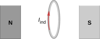
65. \(\displaystyle 2.83×10^{−4}A\), the direction as follows for increasing magnetic field:
67. 0.375 V
69. a. 0.94 V;
b. 0.70 N;
c. 3.52 J/s;
d. 3.52 W
71. \(\displaystyle (\frac{dB}{dt})\frac{A}{2πr}\)
73. a. \(\displaystyle R_f+R_a=\frac{120V}{2.0A}=60Ω\), so \(\displaystyle R_f=50Ω\);
b. \(\displaystyle I=\frac{ε_s−ε_i}{R_f+R_a},⇒ε_i=90V\);
c. \(\displaystyle ε_i=60V\)
Challenge Problems
75. N is a maximum number of turns allowed.
77. 5.3 V
79. \(\displaystyle Φ=\frac{μ_0I_0a}{2π}ln(1+\frac{b}{x})\), so \(\displaystyle I=\frac{μ_0I_0abv}{2πRx(x+b)}ε=\frac{μ_0I_0abv}{2πx(x+b)}\)
81. a. \(\displaystyle 1.01×10^{−6}V\);
b. \(\displaystyle 1.37×10^{−7}V\);
c. 0 V
83. a. \(\displaystyle v=\frac{mgRsinθ}{B^2l^2cos^2θ}\);
b. \(\displaystyle mgvsinθ\);
c. \(\displaystyle mcΔT\);
d. current would reverse direction but bar would still slide at the same speed
85. a. \(\displaystyle B=μ_0nI,Φ_m=BA=μ_0nIA\),
\(\displaystyle ε=9.9×10^{−4}V\);
b. \(\displaystyle 9.9×10^{−4}V\);
c. \(\displaystyle ∮\vec{E}⋅d\vec{l}=ε,⇒E=1.6×10^{−3}V/m\)
d. \(\displaystyle 9.9×10^{−4}V\);
e. no, because there is no cylindrical symmetry
87. a. \(\displaystyle 1.92×10^6rad/s=1.83×10^7rpm\);
b. This angular velocity is unreasonably high, higher than can be obtained for any mechanical system.
c. The assumption that a voltage as great as 12.0 kV could be obtained is unreasonable.
89. \(\displaystyle \frac{2μ_0πa^2I_0nω}{R}\)
91. \(\displaystyle \frac{mRv_o}{B^2D^2}\)