Physics LibreTexts

10.5: Electric Generators

  • Page ID
    47070
  • \( \newcommand{\vecs}[1]{\overset { \scriptstyle \rightharpoonup} {\mathbf{#1}} } \) \( \newcommand{\vecd}[1]{\overset{-\!-\!\rightharpoonup}{\vphantom{a}\smash {#1}}} \)\(\newcommand{\id}{\mathrm{id}}\) \( \newcommand{\Span}{\mathrm{span}}\) \( \newcommand{\kernel}{\mathrm{null}\,}\) \( \newcommand{\range}{\mathrm{range}\,}\) \( \newcommand{\RealPart}{\mathrm{Re}}\) \( \newcommand{\ImaginaryPart}{\mathrm{Im}}\) \( \newcommand{\Argument}{\mathrm{Arg}}\) \( \newcommand{\norm}[1]{\| #1 \|}\) \( \newcommand{\inner}[2]{\langle #1, #2 \rangle}\) \( \newcommand{\Span}{\mathrm{span}}\) \(\newcommand{\id}{\mathrm{id}}\) \( \newcommand{\Span}{\mathrm{span}}\) \( \newcommand{\kernel}{\mathrm{null}\,}\) \( \newcommand{\range}{\mathrm{range}\,}\) \( \newcommand{\RealPart}{\mathrm{Re}}\) \( \newcommand{\ImaginaryPart}{\mathrm{Im}}\) \( \newcommand{\Argument}{\mathrm{Arg}}\) \( \newcommand{\norm}[1]{\| #1 \|}\) \( \newcommand{\inner}[2]{\langle #1, #2 \rangle}\) \( \newcommand{\Span}{\mathrm{span}}\)\(\newcommand{\AA}{\unicode[.8,0]{x212B}}\)

    Learning Objectives

    By the end of this section, you will be able to:

    • Calculate the emf induced in a generator.
    • Calculate the peak emf which can be induced in a particular generator system.

    Electric generators induce an emf by rotating a coil in a magnetic field, as briefly discussed in "Induced Emf and Magnetic Flux." We will now explore generators in more detail. Consider the following example.

    The emf calculated in the example is the average over one-fourth of a revolution. What is the emf at any given instant? It varies with the angle between the magnetic field and a perpendicular to the coil. We can get an expression for emf as a function of time by considering the motional emf on a rotating rectangular coil of width \(w\) and height \(l\) in a uniform magnetic field, as illustrated in Figure \(\PageIndex{2}\).

    The figure shows a schematic diagram of an electric generator with a single rectangular coil. The rotating rectangular coil is placed between the two poles of a permanent magnet shown as two rectangular blocks curved on side facing the coil. The magnetic field B is shown pointing from the North to the South Pole. The North Pole is on the left and the South Pole is to the right and hence the direction of field is from left to right. The angular velocity of the coil is given as omega. The velocity vector v of the coil makes an angle theta with the direction of field.
    Figure \(\PageIndex{2}\): A generator with a single rectangular coil rotated at constant angular velocity in a uniform magnetic field produces an emf that varies sinusoidally in time. Note the generator is similar to a motor, except the shaft is rotated to produce a current rather than the other way around.

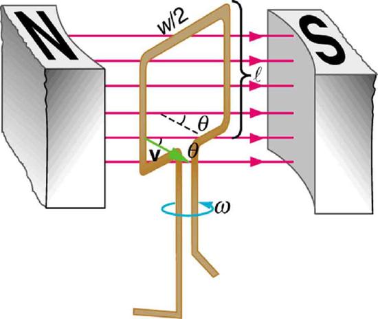
    Charges in the wires of the loop experience the magnetic force, because they are moving in a magnetic field, and a current is generated, which in turn results in an emf across the loop. As the loop turns, the angle between the loop and the magnetic field oscillates continuously between 90 and 0 degrees, and which means the induced emf in the loop also oscillates. As it oscillates, the emf never exceeds a particular maximum value. This is called the peak emf. Figure \(\PageIndex{3}\) shows a graph of emf as a function of time; this corresponds to what is commonly referred to as AC voltage.

    The first part of the figure shows a schematic diagram of a single coil electric generator. It consists of a rotating rectangular loop placed between the two poles of a permanent magnet shown as two rectangular blocks curved on side facing the loop. The magnetic field B is shown pointing from the North to the South Pole. The two ends of this loop are connected to the two small rings. The two conducting carbon brushes are kept pressed separately on both the rings. The loop is rotated in the field with an angular velocity omega. Outer ends of the two brushes are connected to an electric bulb which is shown to glow brightly. The second part of the figure shows the graph for e m f generated E as a function of time t. The e m f is along the Y axis and the time t is along the X axis. The graph is a progressive sine wave with a time period T. The crest maxima are at E zero and trough minima are at negative E zero.
    Figure \(\PageIndex{3}\):The emf of a generator is sent to a light bulb with the system of rings and brushes shown. The graph gives the emf of the generator as a function of time. \(emf_0\) is the peak emf. Note that the script E stands for emf.

    The greater the number of coils, the larger their area, and the stronger the field, the greater the output voltage. Additionally, the faster the generator is spun, the greater the peak emf. This is noticeable on bicycle generators—at least the cheaper varieties. One of the authors as a juvenile found it amusing to ride his bicycle fast enough to burn out his lights, until he had to ride home lightless one dark night.

    Figure shows a scheme by which a generator can be made to produce pulsed DC. More elaborate arrangements of multiple coils and split rings can produce smoother DC, although electronic rather than mechanical means are usually used to make ripple-free DC.

    The first part of the figure shows a schematic diagram of a single coil D C electric generator. It consists of a rotating rectangular loop placed between the two poles of a permanent magnet shown as two rectangular blocks curved on side facing the loop. The magnetic field B is shown pointing from the North to the South Pole. The two ends of this loop are connected to the two sides of a split ring. The two conducting carbon brushes are kept pressed separately on both sides of the split rings. The loop is rotated in the field with an angular velocity w. Outer ends of the two brushes are connected to an electric bulb which is shown to glow brightly. The second part of the figure shows the graph for e m f generated as a function of time. The e m f is along the Y axis and the time t is along the X axis. The graph is a progressive and rectified sine wave with a time period T. The sine wave has only positive pulses. The crest maxima are at E zero.
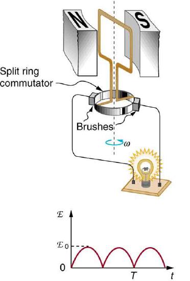
    Figure \(\PageIndex{4}\): Split rings, called commutators, produce a pulsed DC emf output in this configuration.

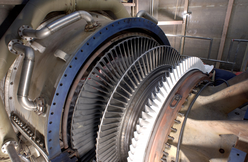
    In real life, electric generators look a lot different than the figures in this section, but the principles are the same. The source of mechanical energy that turns the coil can be falling water (hydropower), steam produced by the burning of fossil fuels, or the kinetic energy of wind. \(\PageIndex{5}\) shows a cutaway view of a steam turbine; steam moves over the blades connected to the shaft, which rotates the coil within the generator.

    Photograph of a steam turbine connected to a generator.
    Figure \(\PageIndex{5}\): Steam turbine/generator. The steam produced by burning coal impacts the turbine blades, turning the shaft which is connected to the generator. (credit: Nabonaco, Wikimedia Commons)

    Generators illustrated in this section look very much like the motors illustrated previously. This is not coincidental. In fact, a motor becomes a generator when its shaft rotates. Certain early automobiles used their starter motor as a generator. In Back Emf, we shall further explore the action of a motor as a generator.

    Summary

    • An electric generator rotates a coil in a magnetic field, inducing an emf that varies in time
    • The faster the rotation, the bigger the peak value of the induced emf

    Glossary

    electric generator
    a device for converting mechanical work into electric energy; it induces an emf by rotating a coil in a magnetic field
    peak emf
    the maximum value attained by the induced emf as the coil is rotated in the magnetic field

    Contributors and Attributions

    • Paul Peter Urone (Professor Emeritus at California State University, Sacramento) and Roger Hinrichs (State University of New York, College at Oswego) with Contributing Authors: Kim Dirks (University of Auckland) and Manjula Sharma (University of Sydney). This work is licensed by OpenStax University Physics under a Creative Commons Attribution License (by 4.0).


    This page titled 10.5: Electric Generators is shared under a CC BY license and was authored, remixed, and/or curated by OpenStax.

    • Was this article helpful?