
11.6: Image Formation by Lenses
- Page ID
- 47079

\( \newcommand{\vecs}[1]{\overset { \scriptstyle \rightharpoonup} {\mathbf{#1}} } \)
\( \newcommand{\vecd}[1]{\overset{-\!-\!\rightharpoonup}{\vphantom{a}\smash {#1}}} \)
\( \newcommand{\dsum}{\displaystyle\sum\limits} \)
\( \newcommand{\dint}{\displaystyle\int\limits} \)
\( \newcommand{\dlim}{\displaystyle\lim\limits} \)
\( \newcommand{\id}{\mathrm{id}}\) \( \newcommand{\Span}{\mathrm{span}}\)
( \newcommand{\kernel}{\mathrm{null}\,}\) \( \newcommand{\range}{\mathrm{range}\,}\)
\( \newcommand{\RealPart}{\mathrm{Re}}\) \( \newcommand{\ImaginaryPart}{\mathrm{Im}}\)
\( \newcommand{\Argument}{\mathrm{Arg}}\) \( \newcommand{\norm}[1]{\| #1 \|}\)
\( \newcommand{\inner}[2]{\langle #1, #2 \rangle}\)
\( \newcommand{\Span}{\mathrm{span}}\)
\( \newcommand{\id}{\mathrm{id}}\)
\( \newcommand{\Span}{\mathrm{span}}\)
\( \newcommand{\kernel}{\mathrm{null}\,}\)
\( \newcommand{\range}{\mathrm{range}\,}\)
\( \newcommand{\RealPart}{\mathrm{Re}}\)
\( \newcommand{\ImaginaryPart}{\mathrm{Im}}\)
\( \newcommand{\Argument}{\mathrm{Arg}}\)
\( \newcommand{\norm}[1]{\| #1 \|}\)
\( \newcommand{\inner}[2]{\langle #1, #2 \rangle}\)
\( \newcommand{\Span}{\mathrm{span}}\) \( \newcommand{\AA}{\unicode[.8,0]{x212B}}\)
\( \newcommand{\vectorA}[1]{\vec{#1}} % arrow\)
\( \newcommand{\vectorAt}[1]{\vec{\text{#1}}} % arrow\)
\( \newcommand{\vectorB}[1]{\overset { \scriptstyle \rightharpoonup} {\mathbf{#1}} } \)
\( \newcommand{\vectorC}[1]{\textbf{#1}} \)
\( \newcommand{\vectorD}[1]{\overrightarrow{#1}} \)
\( \newcommand{\vectorDt}[1]{\overrightarrow{\text{#1}}} \)
\( \newcommand{\vectE}[1]{\overset{-\!-\!\rightharpoonup}{\vphantom{a}\smash{\mathbf {#1}}}} \)
\( \newcommand{\vecs}[1]{\overset { \scriptstyle \rightharpoonup} {\mathbf{#1}} } \)
\(\newcommand{\longvect}{\overrightarrow}\)
\( \newcommand{\vecd}[1]{\overset{-\!-\!\rightharpoonup}{\vphantom{a}\smash {#1}}} \)
\(\newcommand{\avec}{\mathbf a}\) \(\newcommand{\bvec}{\mathbf b}\) \(\newcommand{\cvec}{\mathbf c}\) \(\newcommand{\dvec}{\mathbf d}\) \(\newcommand{\dtil}{\widetilde{\mathbf d}}\) \(\newcommand{\evec}{\mathbf e}\) \(\newcommand{\fvec}{\mathbf f}\) \(\newcommand{\nvec}{\mathbf n}\) \(\newcommand{\pvec}{\mathbf p}\) \(\newcommand{\qvec}{\mathbf q}\) \(\newcommand{\svec}{\mathbf s}\) \(\newcommand{\tvec}{\mathbf t}\) \(\newcommand{\uvec}{\mathbf u}\) \(\newcommand{\vvec}{\mathbf v}\) \(\newcommand{\wvec}{\mathbf w}\) \(\newcommand{\xvec}{\mathbf x}\) \(\newcommand{\yvec}{\mathbf y}\) \(\newcommand{\zvec}{\mathbf z}\) \(\newcommand{\rvec}{\mathbf r}\) \(\newcommand{\mvec}{\mathbf m}\) \(\newcommand{\zerovec}{\mathbf 0}\) \(\newcommand{\onevec}{\mathbf 1}\) \(\newcommand{\real}{\mathbb R}\) \(\newcommand{\twovec}[2]{\left[\begin{array}{r}#1 \\ #2 \end{array}\right]}\) \(\newcommand{\ctwovec}[2]{\left[\begin{array}{c}#1 \\ #2 \end{array}\right]}\) \(\newcommand{\threevec}[3]{\left[\begin{array}{r}#1 \\ #2 \\ #3 \end{array}\right]}\) \(\newcommand{\cthreevec}[3]{\left[\begin{array}{c}#1 \\ #2 \\ #3 \end{array}\right]}\) \(\newcommand{\fourvec}[4]{\left[\begin{array}{r}#1 \\ #2 \\ #3 \\ #4 \end{array}\right]}\) \(\newcommand{\cfourvec}[4]{\left[\begin{array}{c}#1 \\ #2 \\ #3 \\ #4 \end{array}\right]}\) \(\newcommand{\fivevec}[5]{\left[\begin{array}{r}#1 \\ #2 \\ #3 \\ #4 \\ #5 \\ \end{array}\right]}\) \(\newcommand{\cfivevec}[5]{\left[\begin{array}{c}#1 \\ #2 \\ #3 \\ #4 \\ #5 \\ \end{array}\right]}\) \(\newcommand{\mattwo}[4]{\left[\begin{array}{rr}#1 \amp #2 \\ #3 \amp #4 \\ \end{array}\right]}\) \(\newcommand{\laspan}[1]{\text{Span}\{#1\}}\) \(\newcommand{\bcal}{\cal B}\) \(\newcommand{\ccal}{\cal C}\) \(\newcommand{\scal}{\cal S}\) \(\newcommand{\wcal}{\cal W}\) \(\newcommand{\ecal}{\cal E}\) \(\newcommand{\coords}[2]{\left\{#1\right\}_{#2}}\) \(\newcommand{\gray}[1]{\color{gray}{#1}}\) \(\newcommand{\lgray}[1]{\color{lightgray}{#1}}\) \(\newcommand{\rank}{\operatorname{rank}}\) \(\newcommand{\row}{\text{Row}}\) \(\newcommand{\col}{\text{Col}}\) \(\renewcommand{\row}{\text{Row}}\) \(\newcommand{\nul}{\text{Nul}}\) \(\newcommand{\var}{\text{Var}}\) \(\newcommand{\corr}{\text{corr}}\) \(\newcommand{\len}[1]{\left|#1\right|}\) \(\newcommand{\bbar}{\overline{\bvec}}\) \(\newcommand{\bhat}{\widehat{\bvec}}\) \(\newcommand{\bperp}{\bvec^\perp}\) \(\newcommand{\xhat}{\widehat{\xvec}}\) \(\newcommand{\vhat}{\widehat{\vvec}}\) \(\newcommand{\uhat}{\widehat{\uvec}}\) \(\newcommand{\what}{\widehat{\wvec}}\) \(\newcommand{\Sighat}{\widehat{\Sigma}}\) \(\newcommand{\lt}{<}\) \(\newcommand{\gt}{>}\) \(\newcommand{\amp}{&}\) \(\definecolor{fillinmathshade}{gray}{0.9}\)Learning Objectives
By the end of this section, you will be able to:
- List the rules for ray tracking for thin lenses.
- Illustrate the formation of images using the technique of ray tracking.
- Determine power of a lens given the focal length.
Lenses are found in a huge array of optical instruments, ranging from a simple magnifying glass to the eye to a camera’s zoom lens. In this section, we will use the law of refraction to explore the properties of lenses and how they form images.
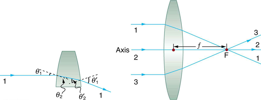
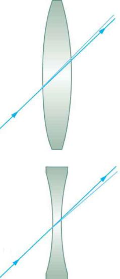
The word lens derives from the Latin word for a lentil bean, the shape of which is similar to the convex lens in Figure 1. The convex lens shown has been shaped so that all light rays that enter it parallel to its axis cross one another at a single point on the opposite side of the lens. (The axis is defined to be a line normal to the lens at its center, as shown in Figure 1.) Such a lens is called a converging (or convex) lens for the converging effect it has on light rays. An expanded view of the path of one ray through the lens is shown, to illustrate how the ray changes direction both as it enters and as it leaves the lens. Since the index of refraction of the lens is greater than that of air, the ray moves towards the perpendicular as it enters and away from the perpendicular as it leaves. (This is in accordance with the law of refraction.) Due to the lens’s shape, light is thus bent toward the axis at both surfaces. The point at which the rays cross is defined to be the focal point F of the lens. The distance from the center of the lens to its focal point is defined to be the focal length \(f\) of the lens. Figure 2 shows how a converging lens, such as that in a magnifying glass, can converge the nearly parallel light rays from the sun to a small spot.
Definition: CONVERGING OR CONVEX LENS
The lens in which light rays that enter it parallel to its axis cross one another at a single point on the opposite side with a converging effect is called converging lens.
Definition: FOCAL POINT F
The point at which the light rays cross is called the focal point F of the lens.
Definition: FOCAL LENGTH \(f\)
The distance from the center of the lens to its focal point is called focal length \(f\).

The greater effect a lens has on light rays, the more powerful it is said to be. For example, a powerful converging lens will focus parallel light rays closer to itself and will have a smaller focal length than a weak lens. The light will also focus into a smaller and more intense spot for a more powerful lens. The power \(P\) of a lens is defined to be the inverse of its focal length:
Definition: POWER \(P\)
The power \(P\) of a lens is defined to be the inverse of its focal length. In equation form, this is
\[P = \frac{1}{f}.\]
where \(f\) is the focal length of the lens, which must be given in meters (and not cm or mm). The power of a lens \(P\) has the unit diopters (D), provided that the focal length is given in meters. That is \(1 D = 1/m\) or \(1 m^{-1}\). (Note that this power (optical power, actually) is not the same as power in watts defined in "Work, Energy, and Energy Resources." It is a concept related to the effect of optical devices on light.) Optometrists prescribe common spectacles and contact lenses in units of diopters.
Example \(\PageIndex{1}\): What is the Power of a Common Magnifying Glass?
Suppose you take a magnifying glass out on a sunny day and you find that it concentrates sunlight to a small spot 8.00 cm away from the lens. What are the focal length and power of the lens?
Strategy:
The situation here is the same as those shown in Figure 1 and Figure 2. The Sun is so far away that the Sun’s rays are nearly parallel when they reach Earth. The magnifying glass is a convex (or converging) lens, focusing the nearly parallel rays of sunlight. Thus the focal length of the lens is the distance from the lens to the spot, and its power is the inverse of this distance (in m).
Solution
The focal length of the lens is the distance from the center of the lens to the spot, given to be 8.00 cm. Thus, \[f = 8.00 cm.\] To find the power of the lens, we must first convert the focal length to meters; then, we substitute this value into the equation for power. This gives \[P = \frac{1}{f} = \frac{1}{0.0800 m} = 12.5 D.\]
Discussion:
This is a relatively powerful lens. The power of a lens in diopters should not be confused with the familiar concept of power in watts. It is an unfortunate fact that the word “power” is used for two completely different concepts. If you examine a prescription for eyeglasses, you will note lens powers given in diopters. If you examine the label on a motor, you will note energy consumption rate given as a power in watts.
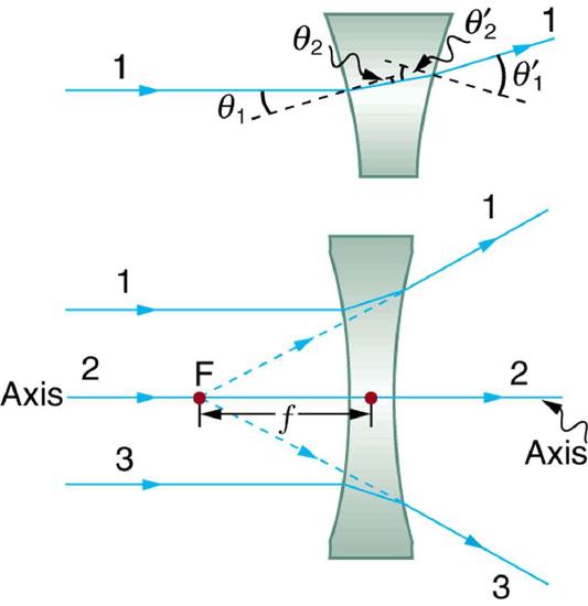
Figure \(\PageIndex{3}\) shows a concave lens and the effect it has on rays of light that enter it parallel to its axis (the path taken by ray 2 in the figure is the axis of the lens). The concave lens is a diverging lens, because it causes the light rays to bend away (diverge) from its axis. In this case, the lens has been shaped so that all light rays entering it parallel to its axis appear to originate from the same point, \(F\), defined to be the focal point of a diverging lens. The distance from the center of the lens to the focal point is again called the focal length \(f\) of the lens. Note that the focal length and power of a diverging lens are defined to be negative. For example, if the distance to \(F\) in Figure 3 is 5.00 cm, then the focal length is \(f = -5.00 cm\) and the power of the lens is \(P = -20D\). An expanded view of the path of one ray through the lens is shown in the figure to illustrate how the shape of the lens, together with the law of refraction, causes the ray to follow its particular path and be diverged.
Definition: DIVERGING LENS
A lens that causes the light rays to bend away from its axis is called a diverging lens.
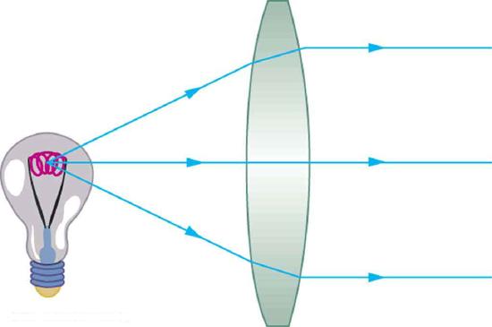
As noted in the initial discussion of the law of refraction in "The Law of Refraction," the paths of light rays are exactly reversible. This means that the direction of the arrows could be reversed for all of the rays in Figures \(\PageIndex{1}\) and Figure \(\PageIndex{3}\). For example, if a point light source is placed at the focal point of a convex lens, as shown in Figure 4, parallel light rays emerge from the other side.
Ray Tracing and Thin Lenses
Ray tracing is the technique of determining or following (tracing) the paths that light rays take. For rays passing through matter, the law of refraction is used to trace the paths. Here we use ray tracing to help us understand the action of lenses in situations ranging from forming images on film to magnifying small print to correcting nearsightedness. While ray tracing for complicated lenses, such as those found in sophisticated cameras, may require computer techniques, there is a set of simple rules for tracing rays through thin lenses. A thin lens is defined to be one whose thickness allows rays to refract, as illustrated in Figure \(\PageIndex{1}\), but does not allow properties such as dispersion and aberrations. An ideal thin lens has two refracting surfaces but the lens is thin enough to assume that light rays bend only once. A thin symmetrical lens has two focal points, one on either side and both at the same distance from the lens (Figure \(\PageIndex{5}\)). Another important characteristic of a thin lens is that light rays through its center are deflected by a negligible amount, as seen in Figure \(\PageIndex{6}\).
Definition: THIN LENS
A thin lens is defined to be one whose thickness allows rays to refract but does not allow properties such as dispersion and aberrations.
TAKE-HOME EXPERIMENT: A VISIT TO THE OPTICIAN
Look through your eyeglasses (or those of a friend) backward and forward and comment on whether they act like thin lenses.
Using paper, pencil, and a straight edge, ray tracing can accurately describe the operation of a lens. The Ruls for Ray Tracing for thin lenses are based on the illustrations already discussed:
RULES FOR RAY TRACING (for thin lenses)
- A ray entering a converging lens parallel to its axis passes through the focal point F of the lens on the other side. (See rays 1 and 3 in Figure \(\PageIndex{1}\)).
- A ray entering a diverging lens parallel to its axis seems to come from the focal point F. (See rays 1 and 3 in Figure \(\PageIndex{3}\)).
- A ray passing through the center of either a converging or a diverging lens does not change direction. (See Figure \(\PageIndex{6}\), and see ray 2 in Figure \(\PageIndex{1}\) and \(\PageIndex{3}\)).
- A ray entering a converging lens through its focal point exits parallel to its axis. (The reverse of rays 1 and 3 in Figure \(\PageIndex{1}\)).
- A ray that enters a diverging lens by heading toward the focal point on the opposite side exits parallel to the axis. (The reverse of rays 1 and 3 in Figure \(\PageIndex{3}\)).
Image Formation by Thin Lenses
In some circumstances, a lens forms an obvious image, such as when a movie projector casts an image onto a screen. In other cases, the image is less obvious. Where, for example, is the image formed by eyeglasses? We will use ray tracing for thin lenses to illustrate how they form images, and we will develop equations to describe the image formation quantitatively.
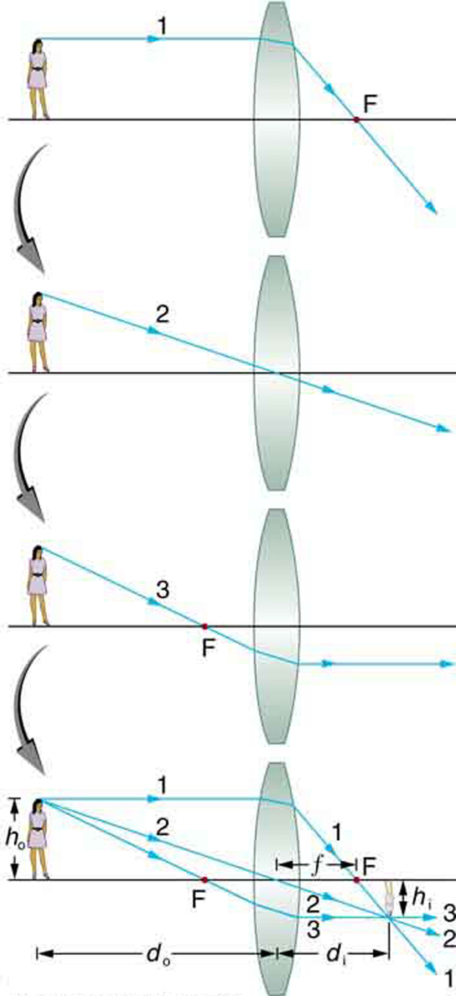
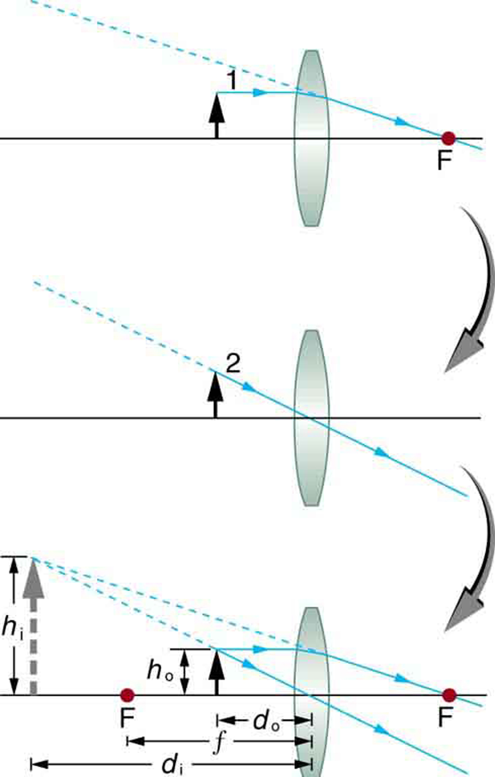
Consider an object some distance away from a converging lens, as shown in Figure \(\PageIndex{7}\). To find the location and size of the image formed, we trace the paths of selected light rays originating from one point on the object, in this case the top of the person’s head. The figure shows three rays from the top of the object that can be traced using the ray tracing rules given above. (Rays leave this point going in many directions, but we concentrate on only a few with paths that are easy to trace.) The first ray is one that enters the lens parallel to its axis and passes through the focal point on the other side (rule 1). The second ray passes through the center of the lens without changing direction (rule 3). The third ray passes through the nearer focal point on its way into the lens and leaves the lens parallel to its axis (rule 4). The three rays cross at the same point on the other side of the lens. The image of the top of the person’s head is located at this point. All rays that come from the same point on the top of the person’s head are refracted in such a way as to cross at the point shown. Rays from another point on the object, such as her belt buckle, will also cross at another common point, forming a complete image, as shown. Although three rays are traced in Figure \(\PageIndex{7}\), only two are necessary to locate the image. It is best to trace rays for which there are simple ray tracing rules. Before applying ray tracing to other situations, let us consider the example shown in Figure 7 in more detail.
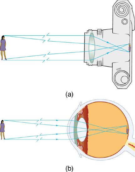
The image formed in Figure \(\PageIndex{7}\) is a real image, meaning that it can be projected. That is, light rays from one point on the object actually cross at the location of the image and can be projected onto a screen, a piece of film, or the retina of an eye, for example. Figure \(\PageIndex{8}\) shows how such an image would be projected onto film by a camera lens. This figure also shows how a real image is projected onto the retina by the lens of an eye. Note that the image is there whether it is projected onto a screen or not.
Definition: REAL IMAGE
The image in which light rays from one point on the object actually cross at the location of the image and can be projected onto a screen, a piece of film, or the retina of an eye is called a real image.
Several important distances appear in Figure 7. We define \(d_{0}\) to be the object of distance, the distance of an object from the center of a lens. Image distance \(d_{i}\) is defined to be the distance of the image from the center of a lens. The height of the object and height of the image are given the symbols \(h_{0}\) and \(h_{i}\), respectively. Images that appear upright relative to the object have heights that are positive and those that are inverted have negative heights. Using the rules of ray tracing and making a scale drawing with paper and pencil, like that in Figure 7, we can accurately describe the location and size of an image. But the real benefit of ray tracing is in visualizing how images are formed in a variety of situations. To obtain numerical information, we use a pair of equations that can be derived from a geometric analysis of ray tracing for thin lenses. The thin lens equations are
\[\frac{1}{d_{0}} + \frac{1}{d_{i}} = \frac{1}{f}\label{25.7.1}\]
and
\[\frac{h_{i}}{h_{0}} = - \frac{d_{i}}{d_{0}} = m.\label{25.7.2}\]
We define the ratio of image height to object height (\(h_{i}/h_{0}\)) to be the magnification \(m\). (The minus sign in the equation above will be discussed shortly.) The thin lens equations are broadly applicable to all situations involving thin lenses (and “thin” mirrors, as we will see later). We will explore many features of image formation in the following worked examples.
Definition: IMAGE DISTANCE
The distance of the image from the center of the lens is called image distance.
Example \(\PageIndex{2}\): Finding the Image of a Light Bulb Filament by Ray Tracing and by the Thin Lens Equations
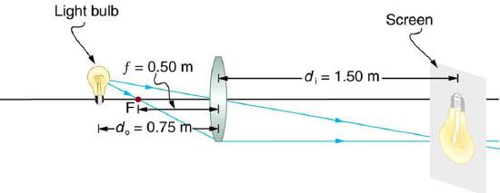
A clear glass light bulb is placed 0.750 m from a convex lens having a 0.500 m focal length, as shown in the figure. Use ray tracing to get an approximate location for the image. Then use the thin lens equations to calculate
- the location of the image and
- its magnification.
Verify that ray tracing and the thin lens equations produce consistent results.
Strategy and Concept
Since the object is placed farther away from a converging lens than the focal length of the lens, this situation is analogous to those illustrated in Figure 7 and Figure 8. Ray tracing to scale should produce similar results for \(d_{i}\). Numerical solutions for \(d_{i}\) and \(m\) can be obtained using the thin lens equations, noting that \(d_{o} = 0.750 m\) and \(f = 0.500 m\).
Solutions (Ray Tracing)
The ray tracing to scale in Figure 9 shows two rays from a point on the bulb’s filament crossing about 1.50 m on the far side of the lens. Thus the image distance \(d_{i}\) is about 1.50 m. Similarly, the image height based on ray tracing is greater than the object height by about a factor of 2, and the image is inverted. Thus \(m\) is about –2. The minus sign indicates that the image is inverted.
The thin lens equations can be used to find \(d_{i}\) from the given information: \[\frac{1}{d_{o}} + \frac{1}{d_{i}} = \frac{1}{f} . \] Rearranging to isolate \(d_{i}\) gives \[\frac{1}{d_{i}} = \frac{1}{f} - \frac{1}{d_{o}}.\] Entering known quantities gives a value for \(1/d_{i}\): \[\frac{1}{d_{i}} = \frac{1}{0.500 m} - \frac{1}{0.750m} = \frac{0.667}{m}.\] This must be inverted to find \(d_{i}\): \[d_{i} = \frac{m}{0.667} = 1.50m .\] Note that another way to find \(d_{i}\) is to rearrange equation: \[\frac{1}{d_{i}} = \frac{1}{f} - \frac{1}{d_{o}}.\] This yields the equation for the image distance as: \[d_{i} = \frac{fd_{o}}{d_{o} - f}.\label{25.7.3}\] Note that there is no inverting here.
The thin lens equations can be used to find the magnification \(m\), since both \(d_{i}\) and \(d_{o}\) are known. Entering their values gives
\[m = -\frac{d_{i}}{d_{o}} = -\frac{1.50 m}{0.750 m} = -2.00. \label{25.7.4}\]
Discussion
Note that the minus sign causes the magnification to be negative when the image is inverted. Ray tracing and the use of the thin lens equations produce consistent results. The thin lens equations give the most precise results, being limited only by the accuracy of the given information. Ray tracing is limited by the accuracy with which you can draw, but it is highly useful both conceptually and visually.
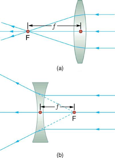
Real images, such as the one considered in the previous example, are formed by converging lenses whenever an object is farther from the lens than its focal length. This is true for movie projectors, cameras, and the eye. We shall refer to these as case 1 images. A case 1 image is formed when \(d_{o} \gt f\) and \(f\) is positive, as in Figure \(\PageIndex{10a}\). (A summary of the three cases or types of image formation appears at the end of this section.)
A different type of image is formed when an object, such as a person's face, is held close to a convex lens. The image is upright and larger than the object, as seen in Figure \(\PageIndex{10b}\), and so the lens is called a magnifier. If you slowly pull the magnifier away from the face, you will see that the magnification steadily increases until the image begins to blur. Pulling the magnifier even farther away produces an inverted image as seen in Figure \(\PageIndex{10a}\). The distance at which the image blurs, and beyond which it inverts, is the focal length of the lens. To use a convex lens as a magnifier, the object must be closer to the converging lens than its focal length. This is called a case 2 image. A case 2 image is formed when \(d_{o} \lt f\) and \(f\) is positive.
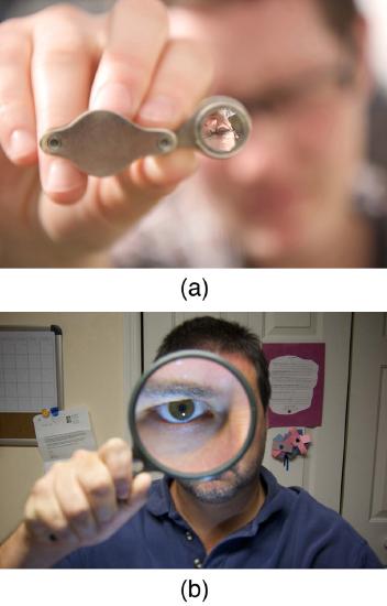
Figure \(\PageIndex{11}\) uses ray tracing to show how an image is formed when an object is held closer to a converging lens than its focal length. Rays coming from a common point on the object continue to diverge after passing through the lens, but all appear to originate from a point at the location of the image. The image is on the same side of the lens as the object and is farther away from the lens than the object. This image, like all case 2 images, cannot be projected and, hence, is called a virtual image. Light rays only appear to originate at a virtual image; they do not actually pass through that location in space. A screen placed at the location of a virtual image will receive only diffuse light from the object, not focused rays from the lens. Additionally, a screen placed on the opposite side of the lens will receive rays that are still diverging, and so no image will be projected on it. We can see the magnified image with our eyes, because the lens of the eye converges the rays into a real image projected on our retina. Finally, we note that a virtual image is upright and larger than the object, meaning that the magnification is positive and greater than 1.
Definition: VIRTUAL IMAGE
An image that is on the same side of the lens as the object and cannot be projected on a screen is called a virtual image.
Example \(\PageIndex{3}\): Image Produced by a Magnifying Glass
Suppose the book in Figure \(\PageIndex{11a}\) is held 7.50 cm from a convex lens of focal length 10.0 cm, such as a typical magnifying glass might have. What magnification is produced?
Strategy and Concept
We are given that \(d_{o} = 7.50 cm\) and \(f = 10.0cm\), so we have a situation where the object is placed closer to the lens than its focal length. We therefore expect to get a case 2 virtual image with a positive magnification that is greater than 1. Ray tracing produces an image like that shown in Figure 11 but we will use the thin lens equations to get numerical solutions in this example.
Solution
To find the magnification \(m\), we try to use magnification equation, \(m = -d_{i}/d_{o}\). We do not have a value for \(d_{i}\), so that we must first find the location of the image using lens equation. (The procedure is the same as followed in the preceding example, where \(d_{o}\) and \(f\) were known.) Rearranging the magnification equation to isolate \(d_{i}\) gives \[\frac{1}{d_{i}} = \frac{1}{f} - \frac{1}{d_{o}}.\] Entering known values, we obtain a value for \(1/d_{i}\): \[\frac{1}{d_{i}} = \frac{1}{10.0 cm} - \frac{1}{7.50 cm} = \frac{-0.0333}{cm}.\] This must be inverted to find \(d_{i}\): \[d_{i} = - \frac{cm}{0.0333} = -30.0 cm.\] Now the thin lens equation can be used to find the magnification \(m\), since both \(d_{i}\) and \(d_{o}\) are known. Entering their values gives \[m = -\frac{d_{i}}{d_{o}} = - \frac{-30.0 cm}{7.50 cm} = 4.00.\]
Discussion
A number of results in this example are true of all case 2 images, as well as being consistent with Figure 11. Magnification is indeed positive (as predicted), meaning the image is upright. The magnification is also greater than 1, meaning that the image is larger than the object—in this case, by a factor of 4. Note that the image distance is negative. This means the image is on the same side of the lens as the object. Thus the image cannot be projected and is virtual. (Negative values of \(d_{i}\) occur for virtual images.) The image is farther from the lens than the object, since the image distance is greater in magnitude than the object distance. The location of the image is not obvious when you look through a magnifier. In fact, since the image is bigger than the object, you may think the image is closer than the object. But the image is farther away, a fact that is useful in correcting farsightedness, as we shall see in a later section.
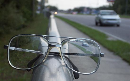
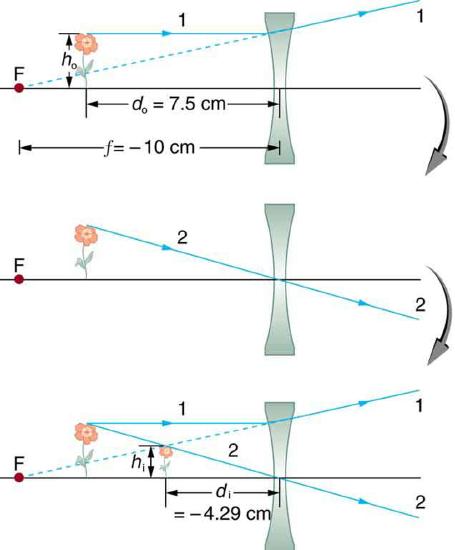
A third type of image is formed by a diverging or concave lens. Try looking through eyeglasses meant to correct nearsightedness. (Figure \(\PageIndex{12}\)). You will see an image that is upright but smaller than the object. This means that the magnification is positive but less than 1. The ray diagram in Figure 13 shows that the image is on the same side of the lens as the object and, hence, cannot be projected—it is a virtual image. Note that the image is closer to the lens than the object. This is a case 3 image, formed for any object by a negative focal length or diverging lens.
Example \(\PageIndex{4}\): Image Produced by a Concave Lens
Suppose an object such as a book page is held 7.50 cm from a concave lens of focal length –10.0 cm. Such a lens could be used in eyeglasses to correct pronounced nearsightedness. What magnification is produced?
Strategy and Concept
This example is identical to the preceding one, except that the focal length is negative for a concave or diverging lens. The method of solution is thus the same, but the results are different in important ways.
Solution
To find the magnification \(m\), we must first find the image distance \(d_{i}\) using thin lens equation
\[\frac{1}{d_{i}} = \frac{1}{f} - \frac{1}{d_{o}},\]
or its alternative rearrangement
\[d_{i} = \frac{fd_{o}}{d_{o} - f}.\]
We are given that \(f = -10.00 cm\) and \(d_{o} = 7.50 cm\). Entering these yields a value for \(1/d_{i}\):
\[\frac{1}{d_{i}} = \frac{1}{-10.0 cm} - \frac{1}{7.50 cm} = \frac{-0.2333}{cm}.\]
This must be inverted to find \(d_{i}\):
\[d_{i} = -\frac{cm}{0.2333} = -4.29 cm.\]
Or \[d_{i} = \frac{\left(7.5\right) \left(-10\right)}{\left(7.5 - \left(-10\right)\right)} = -75/17.5 = -4.29cm.\] Now the magnification equation can be used to find the magnification \(m\), since both \(d_{i}\) and \(d_{o}\) are known. Entering their values gives
\[m = - \frac{d_{i}}{d_{o}} = - \frac{-4.29 cm}{7.50 cm} = 0.571.\]
Discussion:
A number of results in this example are true of all case 3 images, as well as being consistent with Figure 13. Magnification is positive (as predicted), meaning the image is upright. The magnification is also less than 1, meaning the image is smaller than the object -- in this case, a little over half its size. The image distance is negative, meaning the image is on the same side of the lens as the object. (The image is virtual.) The image is closer to the lens than the object, since the image distance is smaller in magnitude than the object distance. The location of the image is not obvious when you look through a concave lens. In fact, since the image is smaller than the object, you may think it is farther away. But the image is closer than the object, a fact that is useful in correcting nearsightedness, as we shall see in a later section.
The table summarizes the three types of images formed by single thin lenses. These are referred to as case 1, 2, and 3 images. Convex (converging) lenses can form either real or virtual images (cases 1 and 2, respectively), whereas concave (diverging) lenses can form only virtual images (always case 3). Real images are always inverted, but they can be either larger or smaller than the object. For example, a slide projector forms an image larger than the slide, whereas a camera makes an image smaller than the object being photographed. Virtual images are always upright and cannot be projected. Virtual images are larger than the object only in case 2, where a convex lens is used. The virtual image produced by a concave lens is always smaller than the object -- a case 3 image. We can see and photograph virtual images only by using an additional lens to form a real image.
| Type | Formed When | Image type | \(d_i\) | m |
|---|---|---|---|---|
| Case 1 | positive f \(d_0>f\) | real | positive | negative |
| Case 2 | positive f \(d_0<f\) | virtual | negative | positive m > 1 |
| Case 3 | negative f | virtual | negative | positive |
In "Image Formation by Mirrors," we shall see that mirrors can form exactly the same types of images as lenses.
TAKE-HOME EXPERIMENT: CONCENTRATING SUNLIGHT
Find several lenses and determine whether they are converging or diverging. In general those that are thicker near the edges are diverging and those that are thicker near the center are converging. On a bright sunny day take the converging lenses outside and try focusing the sunlight onto a piece of paper. Determine the focal lengths of the lenses. Be careful because the paper may start to burn, depending on the type of lens you have selected.
Problem-Solving Strategies for Lenses
- Step 1. Examine the situation to determine that image formation by a lens is involved.
- Step 2. Determine whether ray tracing, the thin lens equations, or both are to be employed. A sketch is very useful even if ray tracing is not specifically required by the problem. Write symbols and values on the sketch.
- Step 3. Identify exactly what needs to be determined in the problem (identify the unknowns).
- Step 4. Make alist of what is given or can be inferred from the problem as stated (identify the knowns). It is helpful to determine whether the situation involves a case 1, 2, or 3 image. While these are just names for types of images, they have certain characteristics (given in the table) that can be of great use in solving problems.
- Step 5. If ray tracing is required, use the ray tracing rules listed near the beginning of this section.
- Step 6. Most quantitative problems require the use of the thin lens equations. These are solved in the usual manner by substituting knowns and solving for unknowns. Several worked examples serve as guides.
- Step 7. Check to see if the answer is reasonable: Does it make sense? If you have identified the type of image (case 1, 2, or 3), you should assess whether your answer is consistent with the type of image, magnification, and so on.
MISCONCEPTION ALERT:
We do not realize that light rays are coming from every part of the object, passing through every part of the lens, and all can be used to form the final image. We generally feel the entire lens, or mirror, is needed to form an image. Actually, half a lens will form the same, though a fainter, image.
Summary
- Light rays entering a converging lens parallel to its axis cross one another at a single point on the opposite side.
- For a converging lens, the focal point is the point at which converging light rays cross; for a diverging lens, the focal point is the point from which diverging light rays appear to originate.
- The distance from the center of the lens to its focal point is called the focal length \(f\).
- Power \(P\) of a lens is defined to be the inverse of its focal length, \(P = \frac{1}{f}\).
- A lens that causes the light rays to bend away from its axis is called a diverging lens.
- Ray tracing is the technique of graphically determining the paths that light rays take.
- The image in which light rays from one point on the object actually cross at the location of the image and can be projected onto a screen, a piece of film, or the retina of an eye is called a real image.
- Thin lens equations are \(\frac{1}{d_{o}} + \frac{1}{d_{1}} = \frac{1}{f}\) and \(\frac{h_{1}}{h_{o}} = m\) (magnification).
- The distance of the image from the center of the lens is called image distance.
- An image that is on the same side of the lens as the object and cannot be projected on a screen is called a virtual image.
Glossary
- converging lens
- a convex lens in which light rays that enter it parallel to its axis converge at a single point on the opposite side
- diverging lens
- a concave lens in which light rays that enter it parallel to its axis bend away (diverge) from its axis
- focal point
- for a converging lens or mirror, the point at which converging light rays cross; for a diverging lens or mirror, the point from which diverging light rays appear to originate
- focal length
- distance from the center of a lens or curved mirror to its focal point
- magnification
- ratio of image height to object height
- power
- inverse of focal length
- real image
- image that can be projected
- virtual image
- image that cannot be projected
Contributors and Attributions
Paul Peter Urone (Professor Emeritus at California State University, Sacramento) and Roger Hinrichs (State University of New York, College at Oswego) with Contributing Authors: Kim Dirks (University of Auckland) and Manjula Sharma (University of Sydney). This work is licensed by OpenStax University Physics under a Creative Commons Attribution License (by 4.0).