
4.2: Magnification


- Last updated
- Nov 8, 2022
- Save as PDF

( \newcommand{\kernel}{\mathrm{null}\,}\)
Lateral Magnification
You may have noticed that in the diagrams for the plane reflector and refractor, we oriented the object arrow so that it was parallel to the reflecting/refracting surface. We should take a moment to say a few words about this, as well as define a few terms.
The horizontal line that is perpendicular to and bisects the surface that causes reflection or refraction is called the optical axis. We will almost exclusively work with object arrows that are oriented perpendicular to this axis, as we did in the previous section. The reason for this is that the "object and image distances" are only well-defined when every point is the same distance from the surface. Shortly we will say a few words about objects that are not oriented so conveniently, but unless explicitly stated, one should assume that this perpendicular-to-optical-axis is in effect.
In the cases of both the plane reflector and plane refractor, we found that the object and image arrows were exactly the same size. This result is special to these cases – in the more general cases we will examine soon, the object and image sizes will be different. We define the lateral magnification of the image as the ratio of the image size y′ to the object size y:
M≡y′y
For both the plane reflector and the plane refractor that we examined in the previous section, this ratio is 1. We know this because when we compute the positions of the head and base of the image arrow, we find that the separations of these points y′ is the same as the distance separating the head and base of the object arrow y.
As with every quantity we will define in geometrical optics, there is a sign convention defined for lateral magnification. We do this by insisting that the values of y and y′ are positive when the arrow is pointing in one direction, and negative when pointing in the other. Let's say we define upward as the positive direction for the two cases we have studied so far. In both cases, an up-oriented object arrow resulted in a up-oriented image arrow, so for both cases y and y′ were both positive. Therefore the lateral magnifications for both cases are positive. Clearly when the orientations of the object and image are the same (either both positive or both negative) – which we have previously defined as "upright") then the magnification is positive, and when the image is inverted relative to the object, the magnification is negative. Adding this sign convention to our list gives:
namesymbolpositive whennegative whenobjectdistancesobjectonincomingsideobjectonothersideimagedistances′imageonoutgoingsideimageonothersidelateralmagnificationMimageuprightimageinverted
Longitudinal Magnification
The word "lateral" is appended above because it only applies to the dimensions of the objects perpendicular to the optical axis. As stated above, this is almost exclusively what we will be working with, but before we forge ahead, let's take a moment to look at magnification in the cases of the plane reflector when the object arrow is parallel to the optical axis.
Calling the object length y, we seek to compute the image length y′. We do this by computing the position of each end of the image arrow separately, and then using those positions to compute the length. The image of each point is exactly the same distance from the reflecting plane on the opposite side:
Figure 4.2.1 – Longitudinal Reflection

The extension of the object is y=s2−s1 and the extension of the image is y′=s′2−s′1, and since, for the plane reflector s=−s′, we get that these are the same length. We can use the same definition for the magnitude of longitudinal magnification as we did for lateral magnification (keeping in mind here that the measurement of y is along the optical axis rather than perpendicular to it), giving:
|M|=|y′||y|=1
The magnitude of 1 indicates the object and image are the same length. We see also that the arrows are pointing in opposite directions, which means the image is inverted. So both the lateral and longitudinal cases of the plane reflector result in images that are neither magnified nor diminished, but in the lateral case the image is upright, while it is inverted in the longitudinal case.
Example 4.2.1
An object in a medium with index of refraction n1 is viewed through a plane refractor from a medium with an index of refraction n2. Find the magnitude of longitudinal magnification of the image, and indicate whether the image is upright or inverted.
- Solution
-
We follow the same procedure as above, computing distances to the refracting plane for the front and rear of the image arrow. Defining, as we did above, s1 and s2 as the object distances of the rear and point respectively of the object arrow, we compute the image distances using Equation 4.1.6 to be:
s′1=−n2n1s1,s′2=−n2n1s2
As above, we write the lengths of the objects and images as the differences of these quantities:
y=s2−s1,y′=s′2−s′1
Putting these together and computing the magnitude gives:
|M|=|y′||y|=|n2n1s2−n2n1s1||s2−s1|=n2n1
So the image is magnified if n2>n1, and diminished if the opposite is true. Clearly the object and image arrows point in the same direction (whichever end of the object is closer to the plane, that same end is closer to the plane for the image) so this image is upright.
Interesting that this result is the exact opposite of the plane reflector – upright instead of inverted, and either magnified or diminished rather than unchanged.
Angular Magnification
As logical as these two definitions of magnification are, neither of them actually captures what we think of when we hear the word "magnification." When an object we see is magnified, we generally mean that we see it better – its details are more evident. An item does not increase in size (its dimensions remain the same), but we can see it better when it is closer. When the light from an object is refracted by a plane such that the image is closer to the viewer than the object, the image and object are the same size, but the image is closer, so we can see it better. This is a condition that most people would refer to as "magnified." Indeed, if you look at a penny at the bottom of a swimming pool, it certainly looks larger than another penny in the same position with the pool empty. So how do we account for this commonsense definition of magnification?
What makes something look large or small regardless of its actual size is the percentage of our field of view that it captures. This is determined by the angle the image subtends in our view. Let's see what this means for the refracting plane. When the object is in a region with a higher index of refraction, we know that the image is the same size as the object, but it is closer to the observer, causing it to subtend a larger angle.
Figure 4.2.2 – Angular Magnification By Refracting Plane
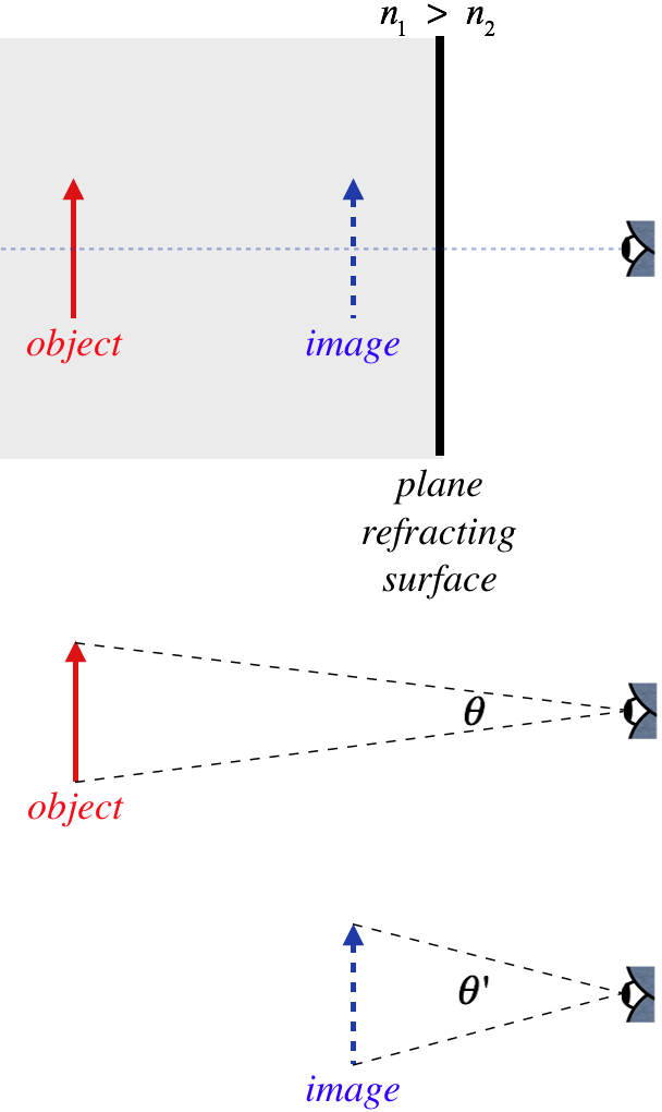
Clearly θ′>θ, which means the image takes up a bigger portion of our field of view than the object would, if it was viewed directly (without the refracting plane). We can measure the amount of this angular magnification with a simple ratio of the angles:
Mθ≡θ′θ
Alert
While we define a sign convention for lateral magnification to indicate whether the image is upright or inverted, for angular magnification, it is standard to only take into account the magnitude, so the directions that the angles are swept-out are not important, and we essentially just use absolute values. It is understood that the lateral magnification takes into account everything about the image, while the angular magnification only handles the size of the field of view that the image occupies.
Example 4.2.2
An object in a medium with index of refraction n1 is viewed through a plane refractor from a medium with an index of refraction n2. If the viewer is positioned right next to the plane refractor, find the angular magnification of the image.
- Solution
-
We can use the figure above, except imagine that the eye is right at the plane. The optical axis divides both the object and image in half, so the ratio of these half-angles will also equal the angular magnification. These angles are part of right triangles formed by the object and image, with one side (the height of half the object/image, which we will call y) being the same for both. The tangents of the angles are therefore:
tanθ=ys,tanθ′=ys′
The angles, as aleways, are assume to be small, so the tangents are approximately equal to the angles themselves (measured in radians), which means we have:
Mθ=θ′θ≈tanθ′tanθ=ys′ys=ss′
Now just plug in Equation 4.1.6:
Mθ=n1n2
Sure enough, an observer looking at an object that is within a medium of higher index of refraction than the surrounding region sees an image that is magnified angularly (i.e. takes up a wider field of view), even though the image is no larger than the object, because the image is just closer.