4.1: Background Material


- Last updated
- Nov 8, 2022
- Save as PDF

( \newcommand{\kernel}{\mathrm{null}\,}\)
Text References
Measuring Resistance
The first part of this lab requires that we measure the resistance through a piece of conducting paper. There are a couple ways we can measure a resistance. The first that comes to mind is to use Ohm's law: Measure the voltage across the "resistor" with a voltmeter, and the current that passes through it with an ammeter, and the ratio of these gives the resistance. But our multimeter does both of these jobs at once – just turn the dial into the ohmmeter region (labeled with an "Ω"), and connect the leads (one in the black COM port and the other in the red VΩHz port) to the opposite ends of the resistor, and the display reads the resistance. You will likely have to adjust the dial to find the right range of values – you can select maximum values from 200Ω to 200MΩ ("M" stands for "mega" = "million").
Resistivity
While resistance is a property of a specific object, resistivity is a property of a material that can have any shape or size. The shape and size combined with the resistivity is what determines an object's resistance. The simplest model to discuss the relationship is a rectangular prism:
Figure 4.1.1 – Resistor Model

The ohmmeter in this figure is measuring the resistance along the direction joining the two leads – down the length L of the prism. If current were to flow along this direction, it would pass through a cross-sectional area equal to the product of the width and thickness: A=wτ. The resistance of this object is related to the resistivity of the material from which it is constructed according to:
R=ρLA
In our lab, we will measure the dimensions of such an object, and use an ohmmeter to measure its resistance, thereby allowing us to compute the resistivity of the material.
Confirmation of Kirchhoff's Rules
The second part of this lab consists of connecting a small network of batteries and resistors in order to confirm Kirchhoff's rules. In order to make this confirmation, one needs to measure both voltage drops with a voltmeter and currents with an ammeter. Both these meters can be selected in the multimeter. The voltmeter you already know from a previous lab. The ammeter section of the dial is labeled with an "A" with dots and dashes after it (not the wavy line). Just as in the case of the voltmeter from the previous lab, this meter is for direct current circuits like we are working with here.
There is one critical piece of information about connecting these two types of meters to measure quantities in a circuit. Not following this can damage (or at least temporarily disable) the ammeter. While voltmeters can be used in a "probing manner" connect each lead to opposite ends of a resistor to measure the voltage drop, ammeters must be connected into the circuit. That is, if you want to measure current with an ammeter, you must disconnect your circuit and connect the ammeter into the branch through which you wish to measure the current. If you are not taking your circuit apart to put your ammeter into it, then you are using the ammeter incorrectly, and are likely to disable your multimeter and aggravate your TA. If you have any questions about your connection, ask your TA for confirmation that your setup is okay before powering it up.
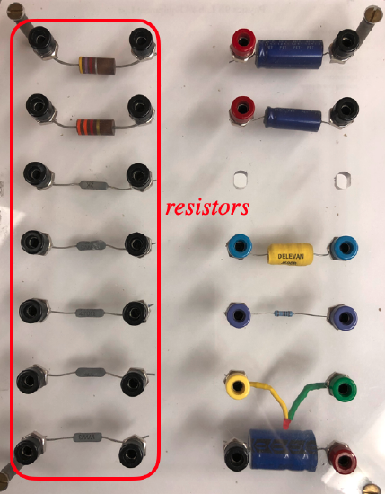
In order to create this network, you will need two batteries and several resistors. The batteries are the plug-in DC power supplies like you used in the previous lab. The resistors you will find on one side of the component board – they are the objects with two black jacks:
Figure 4.1.2 – Component Board